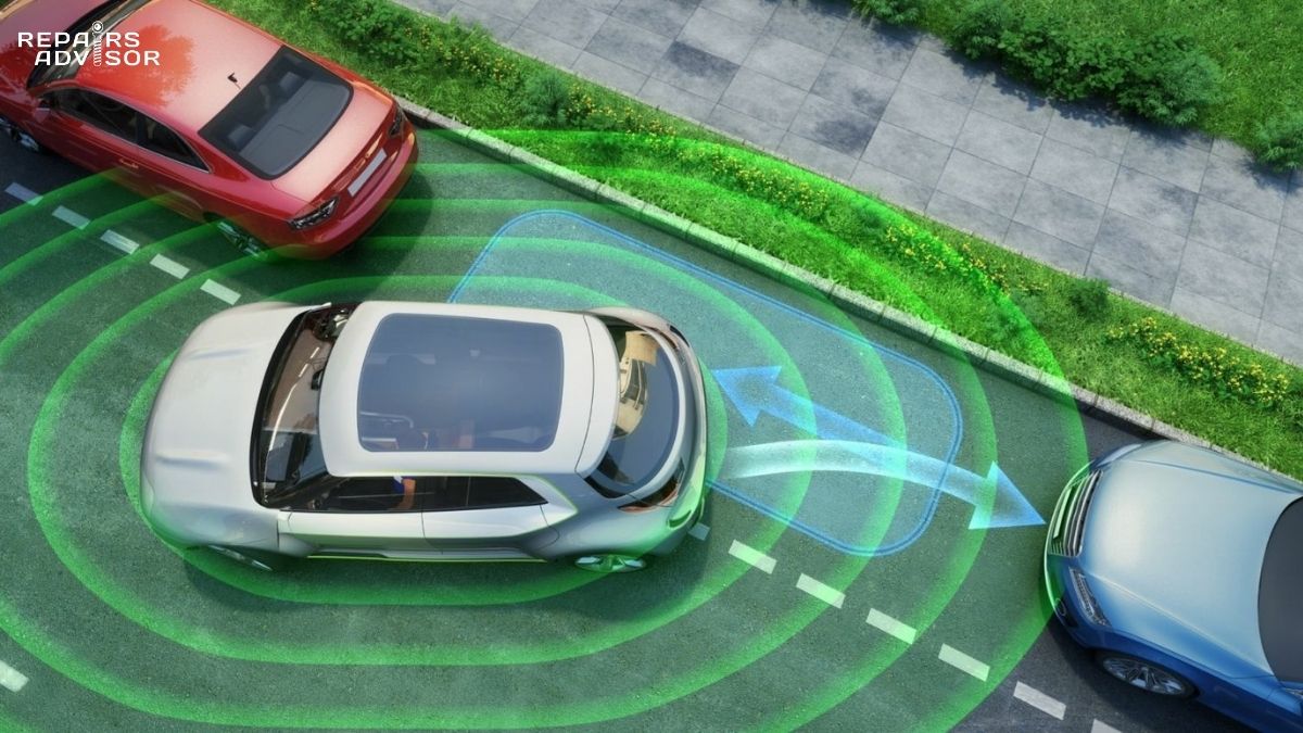
Every time your car automatically brakes before a collision, holds its lane on the highway, or warns you about a vehicle in your blind spot, sensor fusion made that decision possible. It is the invisible computational backbone of every Advanced Driver Assistance System (ADAS) feature in modern vehicles — and increasingly, the reason a seemingly simple repair like replacing a windshield or front bumper now requires specialist calibration equipment. Sensor fusion is the process by which a vehicle’s onboard computers integrate data streams from multiple sensors — cameras, radar, LiDAR, ultrasonic transducers, GPS, and inertial measurement units — into a single, unified, real-time picture of the surrounding environment. What follows explains how that process works, why individual sensors fall short on their own, and what breaks when the fusion system loses its calibration.
Quick Answer
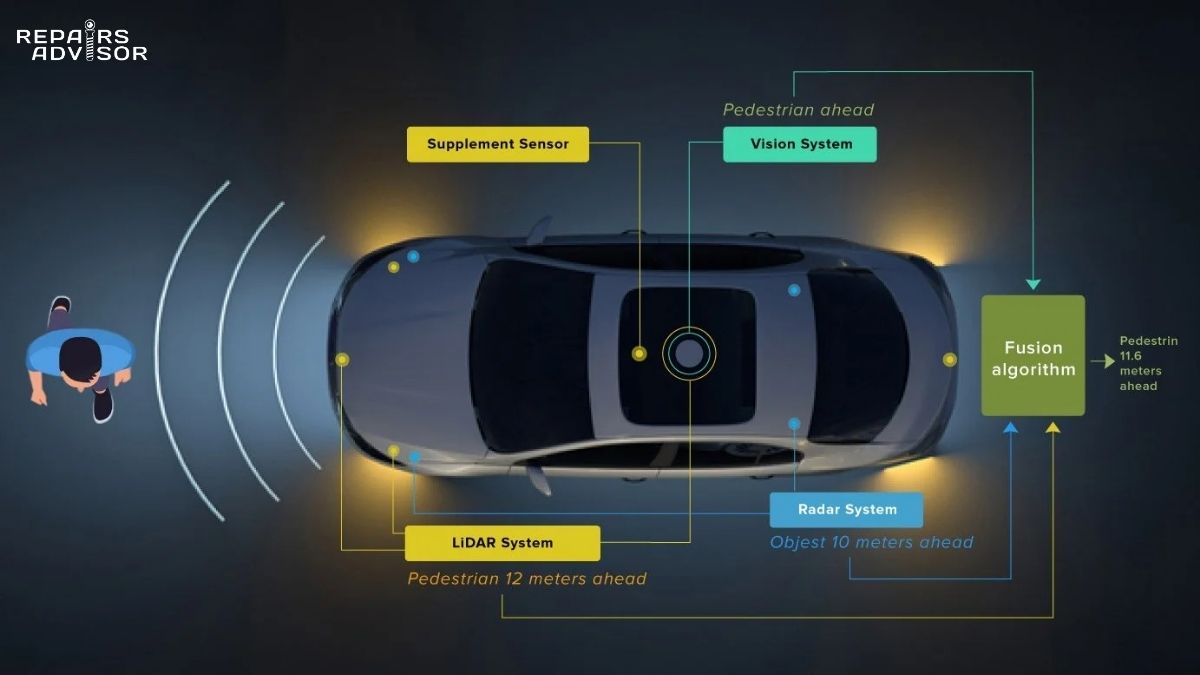
Sensor fusion combines data from cameras, radar, LiDAR, ultrasonic sensors, and inertial measurement units into a single accurate model of the surrounding environment — processed in real time by the vehicle’s ECUs. No single sensor type is reliable on its own: cameras struggle in poor light, radar lacks classification accuracy, and LiDAR is weather-sensitive. Fusion exploits the complementary strengths of all sensors simultaneously, producing the robust perception layer that enables ADAS features from SAE Level 2 adaptive cruise control through to Level 4 high-automation systems. Because fusion accuracy depends on precise sensor alignment, ADAS calibration by a trained technician is required after any repair affecting sensor positions.
Why No Single Sensor Is Enough
The fundamental challenge of automotive perception is that every sensor type has meaningful weaknesses. A vehicle relying on cameras alone will struggle at night, in heavy rain, or when the sun sits directly ahead. A vehicle relying only on radar can track objects at long range but cannot reliably distinguish a pedestrian from a road sign. A vehicle using only LiDAR has extraordinary geometric precision but limited ability to read colour-coded information like traffic lights, and its performance degrades in heavy fog. This is not a technology problem waiting to be solved — it is a physics problem inherent to each sensing modality. Sensor fusion exists precisely because no single approach covers the full range of real-world driving conditions.
The Core Problem — Every Sensor Has a Blind Spot
To understand why fusion matters, it helps to know the specific limitations of each sensor type. Automotive cameras deliver high-resolution visual data — essential for reading lane markings, traffic signs, and classifying object types — but their performance degrades significantly in low light, glare, and adverse weather. In heavy rain or snow, a camera’s effective detection range can drop by more than half. Automotive radar, operating at 77/79 GHz, excels at measuring the distance and closing velocity of objects with high precision across ranges up to 250 metres and works reliably in virtually all weather conditions — but its angular resolution is coarse, meaning it struggles to tell closely-spaced objects apart or classify what it has detected.
LiDAR uses laser pulses to create dense, centimetre-accurate three-dimensional point clouds of the environment, making it exceptional for spatial geometry — but heavy fog or rain can scatter laser pulses, and the technology remains expensive relative to cameras and radar. Ultrasonic sensors, which measure proximity using sound waves at very short range (typically under five metres), are reliable for low-speed parking manoeuvres but contribute nothing to high-speed perception. GPS tells the vehicle where it is on a map but cannot detect surrounding objects at all, and its absolute accuracy can drift or be disrupted by signal blockage in urban canyons. None of these limitations is fatal in isolation — but all of them would be dangerous if that sensor were the sole input to safety-critical decisions.
What Fusion Solves — Redundancy and Accuracy Together
Sensor fusion achieves two goals simultaneously: higher accuracy and built-in redundancy. When camera data confirms what radar has already detected, the system has much higher confidence in that object’s existence, classification, and position than either sensor could provide alone. Research into camera-LiDAR fusion systems shows mean average precision (mAP) scores exceeding 95% for key object classes like cars and pedestrians — significantly higher than radar-only systems. Redundancy means that if one sensor degrades — a camera lens obscured by mud, a radar blocked by a damaged bumper — the remaining sensors can maintain a working perception picture, degrading gracefully rather than failing suddenly. This architectural redundancy is not just a comfort feature; for SAE Level 3 and above autonomy, where the driver may not be monitoring the road, it is a safety requirement built into the vehicle’s design.
The Sensors That Feed the Fusion System
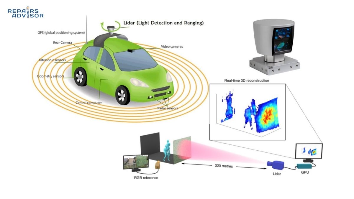
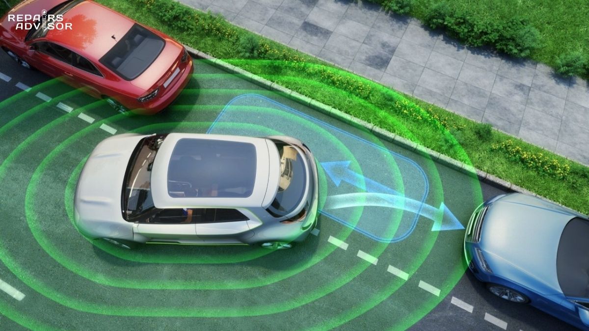
Modern ADAS-equipped vehicles carry multiple sensor types positioned around the vehicle to achieve overlapping fields of view. The specific sensor suite varies by manufacturer and autonomy level, but most fusion-capable vehicles combine at least radar and cameras, with LiDAR, ultrasonics, GPS, and IMU added for higher-capability systems.
Radar — The Speed and Distance Expert
Automotive radar systems broadcast frequency-modulated continuous wave (FMCW) signals and analyse the reflected return to calculate the range, bearing, and radial velocity of surrounding objects — including measuring the relative speed of a target directly via the Doppler effect. Modern vehicles typically carry several radar modules: long-range forward radar (up to 250 m) for adaptive cruise control and forward collision warning, and shorter-range radars covering the sides and rear for blind spot monitoring, rear cross-traffic alert, and lane change assistance. Because radar signals penetrate rain, fog, snow, and darkness without meaningful degradation, radar is the sensor type the fusion system relies on most heavily when camera performance deteriorates. To learn more about the electronics behind this technology, see how automotive radar works.
Camera — The Classification Expert
Cameras are the only sensors that capture the rich visual texture of the environment — the colour of a traffic light, the text on a speed limit sign, the shape that distinguishes a cyclist from a pedestrian. Modern automotive cameras use high dynamic range (HDR) image sensors that can handle the extreme contrast between sunlit and shadowed areas, and many systems deploy multiple cameras — forward-facing at different focal lengths, side cameras, and rearward cameras — to achieve 360-degree coverage. The image processing pipelines behind these cameras are increasingly powered by neural networks trained on millions of labelled images, enabling real-time object detection, lane boundary identification, and traffic sign recognition. The tradeoff is sensitivity to lighting conditions and weather, which is precisely why cameras are paired with radar in production systems. For a deeper look at how the optical and electronic systems inside these cameras work, see the article on how automotive cameras work.
LiDAR — The 3D Mapping Expert
LiDAR sensors fire rapid pulses of laser light and measure the time-of-flight of each returning pulse to build a dense point cloud — a three-dimensional map of all surfaces within range, accurate to centimetres. Where radar gives you distance and velocity for a relatively small number of detected objects, LiDAR gives you the full geometric shape of the environment, including the road surface profile, barrier positions, and the precise spatial relationship between all detected objects. This spatial fidelity is particularly valuable for autonomous driving at higher SAE levels, where the vehicle must navigate complex environments without driver supervision. The primary barriers to widespread adoption are cost (LiDAR systems are significantly more expensive than camera or radar modules) and sensitivity to atmospheric scatter in fog or heavy rain. See how automotive LiDAR works for a detailed explanation of the time-of-flight measurement process and point cloud generation.
Ultrasonic Sensors, IMU, and GPS — The Supporting Cast
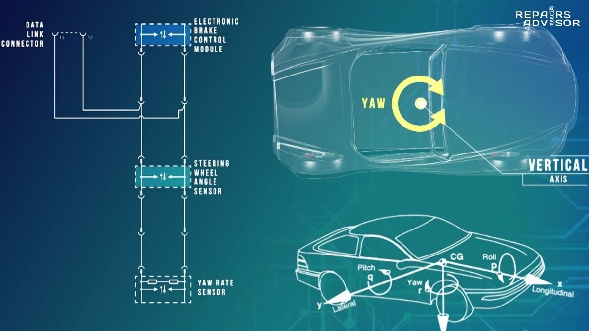
Ultrasonic sensors use piezoelectric transducers to emit high-frequency sound pulses and measure echo return time, providing accurate proximity measurement up to about five metres. Their role in fusion systems is primarily at low speeds — parking assistance, traffic jam following at close range, and blind-spot alerting at very short distances. The inertial measurement unit (IMU) combines accelerometers and gyroscopes to measure the vehicle’s own motion: acceleration in three axes, angular rotation rate around three axes (including yaw, which is also measured by the yaw rate sensor), and lateral acceleration. This data tells the fusion system how the vehicle itself is moving, which is essential context for correctly interpreting what surrounding sensors are detecting. GPS provides the vehicle’s absolute position on a map, enabling map-based context (speed limits, junction geometry, road class) to inform driving decisions. Because GPS can drift and is susceptible to signal blockage, it is typically fused with IMU data and wheel speed sensor inputs to maintain reliable localisation.
The Three Levels of Fusion — When Data Gets Combined
Sensor fusion is not a single technique — it is a family of approaches that differ in when and at what level of abstraction the data from different sensors gets combined. The three main categories are early fusion, mid-level fusion, and late fusion, each with distinct engineering tradeoffs. Understanding these levels matters for technicians because they influence how a failure in one sensor propagates through the system.
Early Fusion (Low-Level) — Raw Data Combined First
In early fusion, the raw output from multiple sensors is merged before any meaningful processing has been applied. The classic example is projecting LiDAR point cloud data onto camera image pixels, combining depth geometry with colour texture at the most fundamental level. Because early fusion retains the maximum possible information from all sensors, it has the highest theoretical accuracy ceiling — but it is computationally intensive, requires precise spatial and temporal alignment between sensors, and means that any noise or error in one sensor’s raw output can propagate directly into the fused data stream. Modern deep learning approaches, particularly Bird’s Eye View (BEV) fusion architectures that project all sensor data onto a unified overhead map representation, are enabling early fusion to become practical in production vehicles and autonomous platforms at a scale that was previously reserved for research systems.
Mid-Level Fusion (Feature-Level) — Extracted Features Combined
Mid-level fusion is currently the dominant approach in production ADAS systems. Rather than merging raw sensor data, each sensor independently extracts intermediate features — object clusters, edges, depth maps, velocity vectors — and the fusion step combines these features. This approach balances accuracy with computational cost: less data is carried forward than in early fusion, but more information is retained than in late fusion. Modern mid-level fusion architectures use cross-modal attention mechanisms to identify which features from one sensor type are most relevant to features from another, dynamically weighting their contributions based on semantic consistency. The ECU processing this fusion step is typically a high-performance domain controller rather than a simple microcontroller — the compute demands are significant.
Late Fusion (High-Level) — Decisions Combined
Late fusion, the classical ADAS architecture, allows each sensor to independently detect and classify objects before the fusion step combines those individual outputs — typically using a Kalman filter to weight and integrate multiple detections of the same object. If both the forward radar and the front camera independently detect an object at a given position, late fusion combines those detections into a single high-confidence track. This approach is modular and fault-tolerant: if the camera fails, the radar continues to provide detections and the system degrades gracefully. The trade-off is that late fusion discards cross-modal information that earlier fusion approaches retain, which can limit its effectiveness in edge cases where individual sensors are producing low-confidence outputs simultaneously. Many modern systems use hybrid architectures that combine late fusion for established object tracks with earlier fusion approaches for novel or uncertain detections.
How Fusion Algorithms Process the Data
Regardless of whether early, mid, or late fusion is applied, the computational pipeline that transforms raw sensor data into actionable driving decisions follows a consistent five-stage structure. This pipeline runs continuously, typically at update rates between 10 and 100 times per second depending on the sensor type and the criticality of the output.
The Kalman Filter — Fusion’s Workhorse
The Kalman filter is the mathematical engine at the heart of most automotive sensor fusion systems. It maintains a running estimate of the state of each tracked object — position, velocity, acceleration — and updates that estimate each time new sensor data arrives. The key insight is that each new measurement is weighted according to its estimated accuracy relative to the current prediction: a high-noise measurement is trusted less than a precise one, while the model’s own prediction provides a baseline that prevents any single bad reading from causing a large position error. For linear systems, the standard Kalman filter works directly. For the non-linear geometries that arise when fusing, for example, radar range-and-bearing data with camera pixel positions, the Extended Kalman Filter (EKF) linearises the problem locally, while the Unscented Kalman Filter (UKF) handles highly non-linear scenarios more robustly. The result is a smoothed, noise-reduced track for each detected object — one the ADAS system can use to predict where that object will be in the next few hundred milliseconds with enough confidence to act on it.
The Five-Stage Perception Pipeline
The complete fusion processing pipeline breaks down into five stages that run continuously — typically 10 to 100 times per second depending on sensor type and feature criticality. In the Detection stage, each sensor collects its raw data: radar returns, camera frames, LiDAR scans, ultrasonic echoes. In the Segmentation stage, the ECU groups incoming data into clusters that may represent individual objects or environmental features — reducing the problem from millions of raw data points to dozens of candidate objects, and significantly cutting false-positive rates in ADAS warnings. The Classification stage applies machine learning models to identify what each cluster actually is: distinguishing pedestrians, cyclists, cars, trucks, barriers, and road debris with increasing accuracy as training datasets have grown. Objects then enter the Tracking and Monitoring stage, where they are assigned persistent identities and followed over time, allowing the system to build trajectory predictions and identify which objects pose future collision risk. Finally, the Decision Logic stage evaluates all tracked objects and their predicted trajectories against the current vehicle state and determines the appropriate response — brake, steer, warn, or take no action. It is this final stage where a calibration error has the most visible consequences: if position data feeding the decision logic is slightly wrong because one sensor is misaligned, the system may respond too early, too late, or not at all.
Deep Learning and AI in Modern Fusion
Increasingly, the distinct stages of the classical pipeline are being replaced or augmented by end-to-end neural network architectures that learn directly from data how to map sensor inputs to driving decisions. BEV (Bird’s Eye View) representations, where all sensor data is projected onto a unified top-down coordinate system, have become a standard architecture because they allow camera, radar, and LiDAR data to be directly combined in a geometrically consistent space. Transformer-based cross-modal attention enables the model to learn which visual features correspond to which LiDAR points or radar returns, making fusion semantically richer than the classical detect-then-fuse approach. These advances push mean average precision for key object classes above 90% in well-controlled conditions, though robustness in genuinely adverse edge cases — heavy fog, unusual objects, sensor degradation — remains an active area of research and development.
Sensor Fusion Powering Real ADAS Features
Sensor fusion is not an abstract engineering concept — it is the direct enabler of the driver assistance features that are now standard or near-standard on most new vehicles. Understanding which sensors contribute to which features helps technicians understand why particular repairs trigger particular calibration requirements.
From SAE Level 2 to Level 5 — Fusion Scales With Autonomy
SAE International’s autonomy taxonomy defines six levels of driving automation. At Level 2 — where most production vehicles sit today — the system can control both steering and speed simultaneously but requires the driver to remain attentive and ready to take over. Features like adaptive cruise control paired with lane centering are classic Level 2 functions, and they already require fusion between at minimum radar (for following distance and closing speed) and cameras (for lane boundary detection). Level 2+ features like hands-free highway driving, which is available on systems such as GM’s Super Cruise and Ford’s BlueCruise, add driver monitoring cameras and high-definition mapping data to the fusion picture, with stricter OEM calibration requirements and more frequent calibration triggers. Level 3 introduces conditional automation where the driver does not need to monitor the road under defined conditions, requiring higher sensor confidence through more robust fusion. Level 4 systems, currently deployed in limited commercial contexts by operators like Waymo, use large sensor suites — Waymo’s vehicles carry 29 cameras alongside multiple LiDAR and radar units — to achieve the redundancy and accuracy needed for fully driverless operation within a defined area. Level 5, full automation in all conditions, is not yet commercially available.
The ADAS Features Driven by Fusion
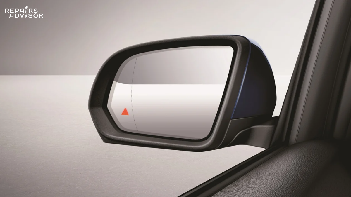
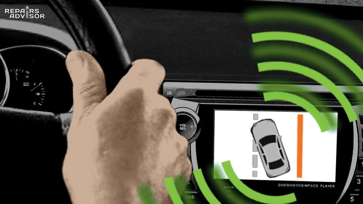
Automatic Emergency Braking (AEB) is perhaps the most safety-critical fusion-dependent feature. It relies on forward radar to establish closing velocity and range, camera systems to classify the detected object (distinguishing a pedestrian from a piece of road debris), and in many implementations LiDAR for precise spatial confirmation, before commanding the braking actuators. Lane departure warning and lane keeping assist are primarily camera-driven, using the forward camera to detect lane markings, but are supplemented by steering angle sensor and IMU data to confirm whether the lane departure is intentional. Blind spot monitoring relies on side-rear radar sensors detecting vehicles in adjacent lanes and fusing that detection with vehicle speed and turn signal state to determine whether a warning is appropriate. Parking assist systems use ultrasonic sensors at close range fused with camera imagery for obstacle detection and, in automated systems, steering angle and wheel speed data for trajectory calculation. At the chassis level, electronic stability control itself is a form of sensor fusion, integrating yaw rate sensor data, lateral accelerometer inputs, steering angle sensor readings, and wheel speed signals to detect and correct vehicle instability — often acting within 20 milliseconds of detecting a slide.
What Can Break Sensor Fusion — and Why Calibration Matters
One of the most important practical consequences of sensor fusion for vehicle owners and technicians is that fusion amplifies calibration errors just as readily as it amplifies correct data. A single miscalibrated sensor does not just degrade that sensor’s own contribution to the fusion picture — it can corrupt the entire output, because the ECU receives contradictory inputs and may be unable to determine which sensor is providing accurate data.
Fusion Amplifies Errors — Not Just Strengths
In the classic single-sensor ADAS architecture — one feature, one sensor — a miscalibrated radar might cause an adaptive cruise control system to hold a slightly different following distance than intended. In a fully fused system, the same miscalibration can cascade: the radar’s position estimate disagrees with the camera’s classification, the Kalman filter receives conflicting inputs, and the fusion system may reduce confidence in its output across multiple features simultaneously. Research and workshop experience both confirm that a miscalibrated camera can degrade radar fusion accuracy even when the radar itself is perfectly aligned, because the raw data mismatch prevents the system from correctly associating detections between sensors. The practical result is that AEB, lane keeping, and blind spot monitoring can all degrade together from a single calibration event — not just the feature most directly associated with the affected sensor.
Common Calibration Triggers
Because ADAS sensors are mounted at precise positions relative to the vehicle’s geometry, any repair or adjustment that changes the physical relationship between a sensor and the vehicle’s centreline or ride height creates a calibration requirement. Windshield replacement is one of the most common triggers: forward-facing cameras mounted near the rearview mirror will shift if the new windshield is installed at a slightly different angle or position, requiring static camera calibration against a target board placed at OEM-specified distances. Front bumper removal or replacement disrupts the alignment of forward radar sensors, affecting adaptive cruise control and forward collision warning. Rear bumper repairs affect rear-facing radar used for blind spot monitoring and rear cross-traffic alert. Suspension work, wheel alignment adjustments, or even tyre changes that alter ride height shift radar aiming angles, since radar beams are calibrated to strike the road at specific angles for ground clutter rejection. Cosmetic repairs involving the areas around sensor housings can also affect ultrasonic sensor performance. The industry trend toward more integrated sensor fusion means that a single repair event increasingly triggers multiple calibration requirements simultaneously — what workshop software providers describe as “chain-reaction calibration.”
Static vs. Dynamic Calibration
ADAS calibration falls into two categories. Static calibration is performed with the vehicle stationary in a controlled environment: technicians place calibration targets — boards with specific geometric patterns — at OEM-specified positions relative to the vehicle, and the vehicle’s diagnostic system uses those known reference points to calculate sensor alignment errors and correct them. Forward-facing cameras, front radar, and many LiDAR systems require static calibration after the relevant sensor or structural components have been replaced. Dynamic calibration is performed while the vehicle is driven at specified speeds on roads with clear lane markings, allowing the system to self-calibrate against known environmental features. Some radar and IMU systems use dynamic calibration. For complex multi-sensor vehicles, both types may be required for a single repair event. Critically, the exact procedure, environmental requirements, and acceptable tolerance vary by OEM — calibration that meets the specification for one manufacturer may be inadequate for another. VIN-accurate calibration lookup is therefore essential to ensure compliance with the correct procedure.
Important: ADAS sensor calibration requires specialist equipment including target boards, calibration frames, and OEM-compatible diagnostic tools. It must be performed according to manufacturer-specified procedures on level ground with controlled lighting and correct tyre pressures. Attempting sensor calibration without the correct equipment and procedures can result in safety systems that appear to function normally but fail to activate correctly in the scenarios they are designed to address. Any repair involving sensors or sensor-adjacent components should include pre- and post-repair diagnostic scans to identify calibration requirements and confirm that all systems have been restored to specification.
Challenges and the Future of Automotive Sensor Fusion
Despite the remarkable capabilities of modern sensor fusion systems, significant technical challenges remain — and understanding them helps explain both the limitations of current ADAS features and the direction the industry is heading.
Current Technical Challenges
Adverse weather represents the most persistent perception challenge. Heavy fog scatters LiDAR pulses, heavy rain degrades camera performance, and even radar — the most weather-resistant sensor type — can see increased ground clutter in wet conditions. More fundamentally, different sensors degrade at different rates in the same weather event, creating asymmetric distortions in the fusion picture that classical fusion algorithms, trained primarily on clear-condition data, can struggle to handle. The temporal synchronisation challenge is less visible but equally significant: cameras, radar, and LiDAR operate at different frame rates and with different processing latencies, and fusing data from sensors that were captured at slightly different moments requires precise timestamping and interpolation to prevent position errors. GPS spoofing — the transmission of false positioning signals — is an emerging security concern addressed by fusing GPS data with IMU, wheel speed sensors, and map data so that a spoofed GPS signal conflicts with dead-reckoning estimates and can be flagged as suspect. Finally, real-time latency constraints are increasingly demanding: autonomous vehicle systems must complete the full perception-to-decision pipeline in under 10 milliseconds for safety-critical interventions, placing significant pressure on the compute hardware that runs fusion algorithms.
What’s Coming
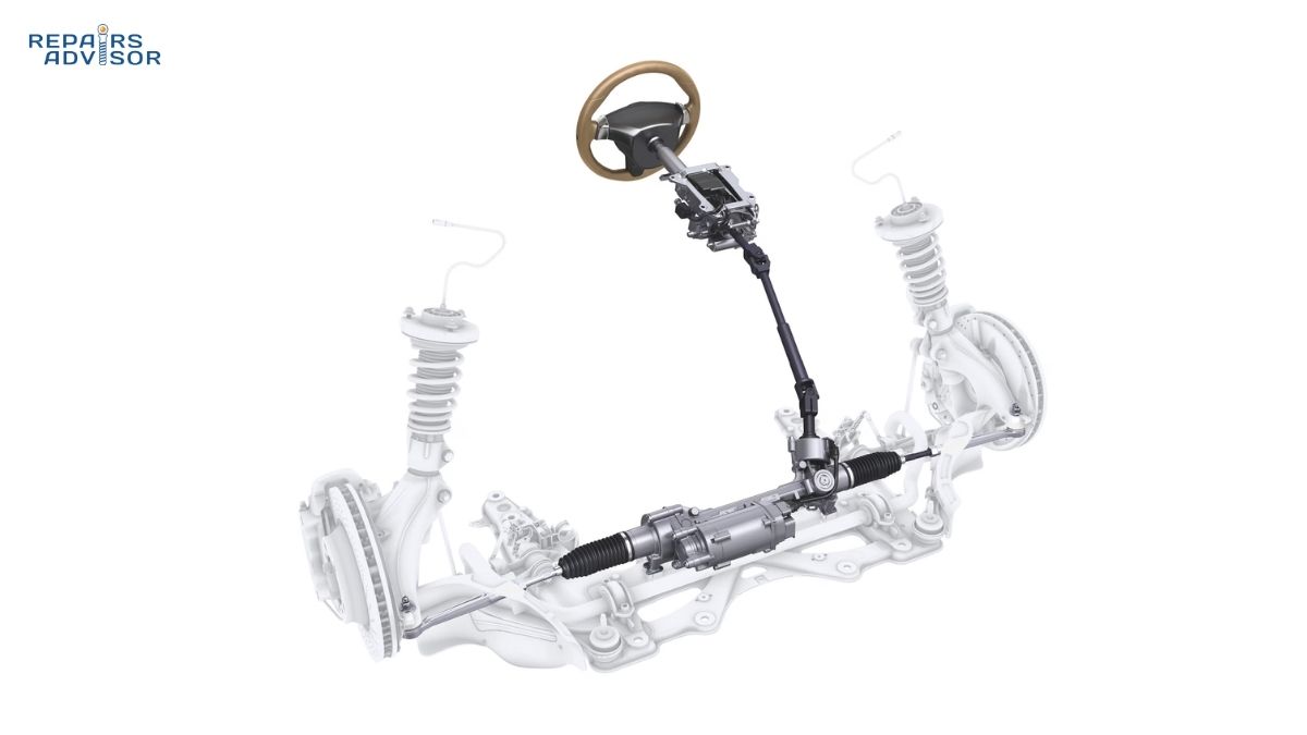
The next generation of automotive radar — sometimes called 4D radar, adding elevation measurement to the traditional range, azimuth, and velocity dimensions — is significantly closing the resolution gap with LiDAR at a fraction of the cost, and its all-weather performance makes it an attractive component in next-generation sensor suites. Vehicle-to-Everything (V2X) communication, which allows vehicles to receive data from roadside infrastructure, traffic management systems, and other vehicles, adds a new data stream to fusion architectures: information about objects and hazards beyond the vehicle’s own sensor range. Software-defined vehicle architectures are centralising fusion processing into powerful domain controllers, enabling over-the-air updates to fusion algorithms that can improve performance across an entire fleet simultaneously — in contrast to the fixed firmware of first-generation ADAS units. The steering angle sensor and other chassis-level inputs will increasingly feed directly into centralised fusion architectures rather than individual feature-specific ECUs, making the vehicle’s entire perception and control stack more integrated and more powerful — and making sensor calibration precision more important than ever.
Understanding the System That Protects You
Sensor fusion is the technology that transforms a collection of imperfect, individually limited sensors into a perception system sophisticated enough to detect pedestrians at night, maintain safe following distances in heavy traffic, and respond to collision threats faster than any human driver. For intermediate DIY enthusiasts, understanding fusion explains why a front bumper repair or windshield replacement that once had nothing to do with electronics now generates a calibration requirement — the sensors behind those panels are part of a tightly interdependent system where alignment precision directly affects safety performance. For professional technicians, the fusion architecture underlines why calibration precision has multiplied in importance: errors propagate across features, and a miscalibration that seems minor in isolation can degrade the entire ADAS stack simultaneously. For drivers new to these systems: if your car has adaptive cruise control or automatic emergency braking, it is running continuous sensor fusion every second you drive. Keeping those sensors aligned is what keeps those features working as designed.
The repair manuals available for specific vehicles provide detailed wiring diagrams, sensor specifications, and OEM calibration procedures for the ADAS systems fitted to those vehicles — reference material that is increasingly valuable as sensor fusion becomes standard equipment across all vehicle segments. When sensors are replaced or disturbed, consulting the manufacturer’s service documentation is the appropriate starting point for understanding what calibration the specific vehicle requires. The complexity of these systems means that pre- and post-repair scanning should be considered standard practice for any work in proximity to ADAS components, ensuring that all systems are confirmed operational and calibrated before the vehicle returns to service. For a closer look at the automatic emergency braking system — one of the most fusion-dependent and safety-critical features in production vehicles — the dedicated technical article covers how radar, camera, and brake system inputs combine to prevent or mitigate collisions.
Sensor Fusion FAQ: Your Questions Answered
Sensor fusion sits at the heart of every modern ADAS feature — from adaptive cruise control to automatic emergency braking — yet most drivers and even many technicians have only a vague picture of how it actually works. These questions cover the fundamentals, the hardware involved, the algorithms that process the data, and the calibration implications that matter most when a vehicle comes in for repair.
Quick Answer
Sensor fusion is the process by which a vehicle’s ECUs combine data from multiple sensors — cameras, radar, LiDAR, ultrasonic sensors, and IMUs — into a single, unified picture of the surrounding environment. Because no sensor type is reliable on its own in all conditions, fusion exploits their complementary strengths to produce the accurate, redundant perception that ADAS features depend on. Any repair that disturbs a sensor’s physical position requires recalibration to restore fusion accuracy.
The Fundamentals
What exactly is sensor fusion in a car?
Sensor fusion is the computational process of combining data streams from multiple sensor types — cameras, radar, LiDAR, ultrasonic sensors, GPS, and inertial measurement units — into a single, coherent model of the environment around the vehicle. Rather than each sensor feeding its output independently to a separate ADAS feature, the vehicle’s domain controller integrates all inputs simultaneously, resolving contradictions between them and producing a higher-confidence picture of the world than any individual sensor could deliver. Think of it as the difference between making a decision based on one witness account versus cross-referencing several independent accounts: the more sources that agree, the more reliable the conclusion.
Why can’t a vehicle just use one sensor type?
Every sensor modality has fundamental physical limitations that no amount of engineering can fully overcome. Cameras provide rich visual detail but degrade in darkness, glare, and heavy rain. Radar measures speed and distance reliably in all weather but has coarse angular resolution and cannot classify objects well. LiDAR maps geometry with centimetre precision but is expensive and sensitive to atmospheric scatter in fog. Ultrasonic sensors are accurate at close range but useless beyond five metres. No single technology covers the full range of real-world driving conditions reliably — fusion is the engineering answer to that physical reality, with each modality compensating for the others’ weaknesses.
Which ADAS features rely on sensor fusion?
Virtually all of them at some level. Automatic emergency braking fuses forward radar and camera data — radar establishes closing velocity and range, camera confirms what the object is. Lane departure warning and lane keeping assist are primarily camera-driven but supported by steering angle sensor and IMU inputs. Blind spot monitoring fuses side-rear radar detections with vehicle speed and turn signal state. Parking assist combines ultrasonic proximity data with camera imagery for obstacle detection. Even electronic stability control is a form of sensor fusion, integrating yaw rate, lateral acceleration, steering angle, and wheel speed inputs to detect and correct instability — often within 20 milliseconds of a slide beginning.
How does sensor fusion relate to SAE autonomy levels?
More autonomy demands more fusion. At SAE Level 2 — where most production vehicles sit — fusion between at minimum radar and cameras enables simultaneous speed and steering control, but the driver must remain attentive. Level 2+ systems add driver-monitoring cameras and high-definition map data to the fusion picture for hands-free highway driving. Level 3 introduces conditional automation with higher sensor confidence requirements. Level 4 systems, currently deployed commercially in limited contexts, use large sensor suites with full redundancy — Waymo’s vehicles, for example, carry 29 cameras alongside multiple radar and LiDAR units — to achieve the reliability needed for driverless operation within a defined area. The key principle: as the driver’s role diminishes, the fusion system must be increasingly fault-tolerant, which means more sensors, more overlap, and tighter calibration tolerances.
The Sensors and Algorithms
What is the Kalman filter, and why does it matter for fusion?
The Kalman filter is the core algorithm behind most production sensor fusion systems. It maintains a continuously updated estimate of each tracked object’s position, velocity, and trajectory, combining the model’s own prediction of where an object should be with each new incoming sensor measurement. Crucially, it weights each measurement by its estimated reliability: a high-noise reading is trusted less than a precise one. This means the filter is naturally resistant to sensor glitches — a single bad reading does not wildly shift the tracked position of an object. For non-linear sensor geometries (such as combining radar polar coordinates with camera pixel positions), variants called the Extended Kalman Filter and the Unscented Kalman Filter extend the approach to handle more complex real-world scenarios. The output is a smoothed, noise-reduced track for every detected object that ADAS decision logic can act on with confidence.
What is the difference between early, mid-level, and late fusion?
These terms describe when in the processing pipeline the data from different sensors gets combined. Early fusion merges raw sensor data before any processing — for example, projecting LiDAR point clouds onto camera pixels. It retains the most information but requires the highest compute resources and precise sensor synchronisation. Mid-level fusion combines intermediate features extracted independently from each sensor, such as object outlines or velocity vectors — it is the dominant architecture in current production ADAS systems because it balances accuracy with computational practicality. Late fusion allows each sensor to independently detect and classify objects before combining those final outputs, typically via a Kalman filter. It is the most modular and fault-tolerant approach — if one sensor fails, the others continue to contribute — but it discards some cross-sensor information in the process. Many modern systems use hybrid architectures that blend elements of all three.
Calibration and Repair Implications
Why does sensor fusion make calibration after repairs so important?
Fusion amplifies errors as readily as it amplifies correct data. In a single-sensor ADAS system, a slightly misaligned radar might cause adaptive cruise control to hold a marginally different following distance. In a fused system, that same misalignment can corrupt the fusion output across multiple features simultaneously, because the ECU receives contradictory inputs from different sensors and cannot reliably determine which is accurate. A miscalibrated camera can degrade radar fusion accuracy even when the radar itself is perfectly aligned — and the resulting degradation may affect AEB, lane keeping, and blind spot monitoring at the same time, all from a single calibration error. Post-repair calibration is not optional for safety: it is the step that restores fusion integrity.
Which repairs commonly trigger ADAS calibration requirements?
Any repair that changes the physical relationship between a sensor and the vehicle’s reference geometry can create a calibration need. The most common triggers include: windshield replacement (forward-facing cameras shift if the new glass sits at a slightly different angle); front bumper removal or replacement (disrupts forward radar alignment, affecting adaptive cruise control and forward collision warning); rear bumper repairs (affects rear radar used for blind spot monitoring and rear cross-traffic alert); suspension work or wheel alignment (changes ride height and therefore radar beam angles); and tyre size changes. Because fused systems share sensors across features, a single repair can cascade into multiple calibration requirements — what the industry calls chain-reaction calibration. Pre- and post-repair diagnostic scanning is the reliable way to identify exactly what each specific vehicle needs.
What is the difference between static and dynamic ADAS calibration?
Static calibration is performed with the vehicle stationary in a controlled environment. Technicians place manufacturer-specified target boards at precise distances from the vehicle, and the diagnostic system uses those known reference positions to calculate and correct sensor alignment errors. Forward-facing cameras and front radar typically require static calibration after replacement or disturbance. Dynamic calibration is performed while driving at specified speeds on roads with clear lane markings, allowing certain sensors — some radar modules and IMU-based systems — to self-calibrate against environmental features. Both types may be required following a single repair event, depending on the vehicle’s sensor configuration. VIN-accurate lookup of OEM procedures is essential because calibration requirements vary significantly between manufacturers, model years, and trim levels — the procedure for one vehicle is not reliably applicable to another.
Can sensor fusion systems detect when a sensor is failing?
To a significant degree, yes. When a sensor begins producing data that consistently conflicts with inputs from other sensors in the fusion system, the ECU’s confidence weighting will begin to down-weight that sensor’s contribution — in some systems, flagging it as suspect and generating a diagnostic trouble code. This is one of the core advantages of redundant fusion architectures: the system can detect sensor degradation by looking for persistent disagreement between channels, rather than waiting for a complete failure. However, not all degradation modes are detectable this way. A sensor that is consistently misaligned — producing plausible but systematically offset data — may not trigger a conflict flag, because its output is internally consistent even if geometrically wrong. This is why post-repair calibration verification matters even when no warning lights are illuminated. The articles on yaw rate sensors and wheel speed sensors cover the individual failure modes of two chassis-level inputs that feed directly into fusion systems.