Every time you press the accelerator, your engine has milliseconds to decide how much fuel to inject and when to fire the spark. The MAP sensor — short for Manifold Absolute Pressure — is one of the key inputs driving that decision. Sitting quietly on or near your intake manifold, this small sensor monitors the pressure inside the intake tract and feeds a continuous stream of load data to the engine control unit. When it’s working correctly, your engine runs smoothly, efficiently, and cleanly. When it starts to fail, the effects show up fast: rough idle, poor fuel economy, hesitation under acceleration, and a check engine light that won’t go away.
Quick Answer
A MAP (Manifold Absolute Pressure) sensor measures pressure inside the intake manifold and outputs a proportional voltage — around 1–1.5V at idle, climbing to 4–4.5V at wide-open throttle. The ECU uses this signal to calculate engine load and set fuel injection and ignition timing in real time. Failure symptoms include rough idle, stalling, poor fuel economy, hesitation under acceleration, and check engine codes P0105 through P0109. An OBD-II scan followed by inspection of the vacuum hose and wiring resolves most faults without touching the sensor; when replacement is needed, parts run $30–$110, with professional service totalling $130–$230.
What Is a MAP Sensor and Where Is It Located?
The MAP sensor is a pressure transducer that converts intake manifold vacuum into a proportional electrical voltage. Unlike a gauge-pressure sensor — which measures pressure relative to atmospheric — a MAP sensor measures absolute pressure referenced against a sealed internal vacuum. This distinction matters because it allows the sensor to compensate for altitude changes automatically, providing accurate data whether you’re driving at sea level or in the mountains.
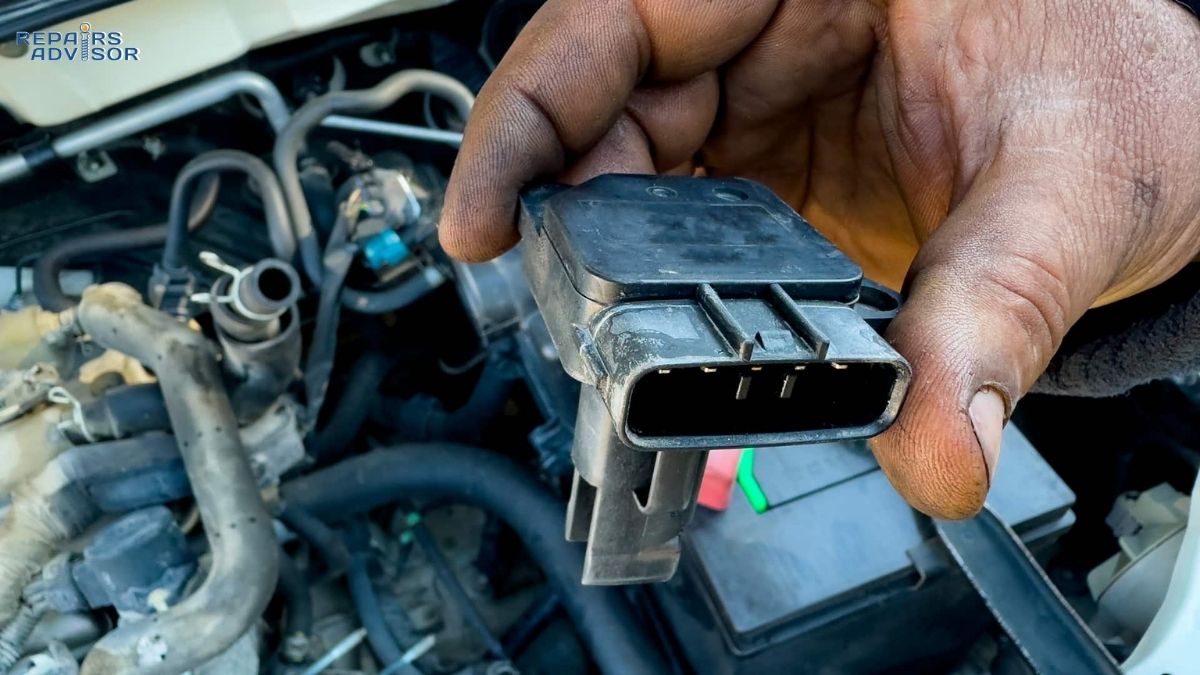
Physically, the MAP sensor is a compact unit, typically housed in a durable polymer block about the size of a matchbox. Inside, a thin silicon diaphragm separates the sealed reference vacuum from the intake manifold pressure. A three-wire connector handles power and communication: a 5-volt reference signal from the ECU, a ground wire, and a signal wire that carries the voltage output back to the computer.
Location varies by vehicle design. On most fuel-injected engines, the MAP sensor mounts directly on the intake manifold or on the throttle body. On older designs, it connects remotely via a rubber vacuum hose — the sensor itself may be mounted on the firewall, inner fender, or air cleaner housing. On turbocharged engines, MAP sensor placement shifts; it may be located post-intercooler to monitor boost pressure in addition to, or instead of, vacuum.
How the MAP Sensor Works: The Physics Behind It
Understanding what the MAP sensor actually does inside that polymer housing helps explain why a failing sensor causes such a wide range of symptoms — and why diagnosis needs to be systematic rather than a straight swap-and-hope approach.
Pressure to Voltage — The Conversion Process
Inside the MAP sensor, four strain gauges (R1 through R4) are bonded to the silicon diaphragm and wired into a Wheatstone bridge circuit. When manifold pressure changes, the diaphragm flexes. That flex changes the physical tension on the strain gauges, which changes their electrical resistance, which shifts the voltage output of the bridge circuit. An integrated amplifier processes that raw signal and outputs a clean, proportional voltage to the ECU.
The signal range follows a predictable pattern: at idle, intake manifold vacuum is high (low absolute pressure), so the MAP sensor outputs a relatively low voltage — typically around 1 to 1.5 volts. As you open the throttle and manifold vacuum drops, pressure rises and the sensor voltage climbs. At wide-open throttle, output typically reaches 4 to 4.5 volts. The ECU receives this constantly updating signal and uses it as the primary indicator of how hard the engine is working.
What the ECU Does With MAP Data
Raw manifold pressure data is useful, but the ECU doesn’t act on it alone. It combines the MAP signal with RPM data from the crankshaft position sensor to run a speed-density calculation — effectively computing how much air is entering the cylinders at that exact moment. The result gets cross-referenced against a volumetric efficiency (VE) table programmed into the ECU, which maps out how efficiently the engine fills its cylinders at various speeds and loads. From that, the ECU determines exactly how much fuel the injectors should deliver.
MAP data also directly influences ignition timing. Under light load and high vacuum, the ECU advances timing aggressively for fuel efficiency. Under heavy load with low vacuum, it pulls timing back to prevent detonation. This dual role — shaping both fuel injection and spark timing — is why a single bad MAP reading degrades so many aspects of engine behaviour at once.
There’s also a useful baseline function: when you first turn the ignition key before cranking the engine, the ECU reads the MAP sensor output with the engine off. This gives a barometric pressure reading (ambient atmospheric pressure), which the computer uses as a reference point for all subsequent load calculations. It’s how fuel-injected engines automatically compensate for driving at altitude.
MAP Sensor vs MAF Sensor — What’s the Difference?
Both sensors exist to help the ECU estimate airflow, but they take fundamentally different approaches. Understanding the distinction is useful if you’re diagnosing an air/fuel issue and aren’t sure which sensor is relevant to your vehicle.
A mass air flow (MAF) sensor measures airflow directly — a heated wire or film element sits in the intake stream, and the cooling effect of passing air corresponds to a precise airflow measurement. This is a direct measurement system, which makes it highly accurate under normal conditions.
The MAP sensor takes an indirect approach. It measures pressure, then the ECU calculates estimated airflow by combining that pressure reading with intake air temperature, RPM, engine displacement, and the VE table. This method — called speed density — produces a calculated estimate rather than a direct measurement. It’s slightly less precise in theory, but it’s more robust in harsh environments (dust, vibration, extreme temperatures) and far easier to tune for high-performance or heavily modified engines.
Most modern passenger cars use MAF-only systems for emissions precision. Many trucks, off-road vehicles, and older cars rely on MAP-only speed density systems. Turbocharged engines often run both: the MAF handles normal airflow measurement while the MAP monitors boost pressure in the charged intake tract. If your vehicle has both sensors, a fault in either one produces its own distinct symptom profile and code set — knowing which system your engine uses before starting diagnosis avoids chasing the wrong sensor.
Symptoms of a Bad MAP Sensor
A failing MAP sensor doesn’t always fail completely and suddenly. More often it degrades gradually — giving intermittent wrong readings that the ECU tries to compensate for, with increasingly noticeable driveability consequences. Here are the most common signs to watch for.
Check Engine Light and Diagnostic Trouble Codes
The check engine light is typically the first dashboard warning, and in many cases it’s accompanied by one or more stored codes. The primary MAP sensor trouble codes are P0105 (circuit malfunction), P0106 (circuit range or performance issue), P0107 (circuit low voltage), P0108 (circuit high voltage), and P0109 (circuit intermittent). It’s important to understand that these codes point to the MAP sensor circuit — they don’t automatically confirm the sensor itself has failed. The fault could lie in the wiring, the connector, the vacuum hose, or the sensor element. Diagnosis should confirm which component is actually at fault before any parts are ordered.
Rough Idle and Stalling
Idle is where engines are most sensitive to fuel mixture errors. At idle, there’s no pedal input to mask instability, and the ECU is working hard to maintain a steady RPM on a small throttle opening. A MAP sensor sending incorrect pressure data causes the ECU to deliver too much or too little fuel, producing a rough, surging idle. In more severe cases the engine stalls — particularly at traffic lights or immediately after a cold start before the system enters closed-loop operation. If your engine shudders at idle or dies unexpectedly at stops, a faulty MAP reading is a strong candidate.
Poor Fuel Economy
When the MAP sensor reads low or no vacuum, the ECU interprets this as a heavy-load condition and enriches the fuel mixture accordingly — even if the engine is barely working. The result is excessive fuel consumption: you’ll notice you’re filling up more frequently without any change in driving habits. This “running rich” condition also produces sooty deposits on spark plugs over time and can contribute to carbon buildup on intake valves in direct injection engines.
Hesitation and Lack of Power
The opposite failure mode — a MAP sensor reading artificially high vacuum — causes the ECU to assume the engine is under light load. It cuts fuel delivery and retards ignition timing. The result is a flat spot on acceleration: the engine responds sluggishly to throttle input, particularly noticeable when merging onto a motorway, overtaking, or climbing hills. This symptom is easy to confuse with a fuel delivery issue, which is another reason proper diagnosis matters.
Black Exhaust Smoke and Failed Emissions Testing
Persistent rich running from a faulty MAP reading produces incomplete combustion, which shows up as black smoke from the exhaust — the visual signature of excess unburned fuel. Beyond the environmental impact, this excess fuel contacts the catalytic converter, which can overheat and fail prematurely if the condition continues. A failed emissions inspection — even without other obvious symptoms — sometimes traces back to a MAP sensor fault at its root.
Common Causes of MAP Sensor Failure
Knowing why MAP sensors fail helps you target your inspection and avoid replacing a good sensor when the real problem is somewhere upstream.
Sensor contamination is one of the most common culprits, particularly on engines with high crankcase blow-by or oil vapour in the intake. Over time, oil mist, carbon particles, and moisture coat the pressure port and the silicon diaphragm, dulling its sensitivity and causing sluggish or inaccurate readings. The sensor may not be electrically faulty — it’s mechanically impaired by deposits.
Vacuum hose failure applies specifically to remote-mounted MAP sensors connected via a rubber hose. These hoses age, crack, collapse, and occasionally pull loose from their fittings. When the hose leaks or disconnects, the sensor reads atmospheric pressure regardless of what’s happening in the manifold — triggering codes and symptoms that perfectly mimic sensor failure even though the sensor itself is fine. Always inspect the vacuum hose before condemning the sensor.
Electrical faults — corroded connector pins, chafed wiring, or broken signal wires — can interrupt the sensor’s output at any point in the circuit. These produce codes quickly and can be intermittent, appearing and disappearing as the harness flexes with engine movement. Wiggling the harness while monitoring live MAP data is a useful test for intermittent electrical faults.
It’s also worth noting that vacuum leaks elsewhere in the intake system can produce MAP-related codes and symptoms without any fault in the sensor itself. Unmetered air entering through a cracked hose, failed intake gasket, or loose fitting throws off the pressure reading the sensor reports. A smoke test or careful visual inspection of all intake vacuum lines is a valuable early step in any MAP sensor diagnosis.
How to Diagnose a MAP Sensor
Systematic diagnosis saves time and money. The steps below cover the most practical sequence for intermediate DIYers. Work with the parking brake set, in a ventilated area, and consult your vehicle’s service manual for model-specific wiring diagrams and exact voltage specifications before testing — values can vary between makes and models.
Step 1 — Scan for DTCs and Review Live Data
Connect an OBD-II scanner and pull all stored and pending codes — not just the MAP-related ones. Related codes for the oxygen sensor, throttle position sensor, or idle control can appear alongside MAP codes when a single underlying issue (like a vacuum leak) affects multiple sensors simultaneously. Check live data: with the ignition on and engine off, the MAP reading should closely match local barometric pressure — approximately 101 kPa or 14.7 psi at sea level. Once the engine is running at idle, MAP should drop to reflect intake vacuum, typically 25–45 kPa depending on the engine. An erratic, flat, or implausible reading in live data is a strong indicator of sensor or circuit trouble.
Step 2 — Visual Inspection of Hose and Wiring
Before touching a multimeter, spend two minutes looking. Inspect the vacuum hose (if present) along its full length for cracks, kinks, collapsed sections, or loose connections at either end. Squeeze the hose — deteriorated rubber loses its firmness and collapses under vacuum. Check the sensor’s electrical connector for corrosion, green oxidation on the pins, or backed-out terminals. Follow the wiring harness toward the ECU and look for chafing against hot or sharp engine components. A large proportion of MAP sensor faults resolve at this step with no parts required.
Step 3 — Multimeter Voltage Test
With the ignition on and engine off, probe the signal wire (centre wire on most 3-wire sensors — verify with your service manual) relative to the sensor ground. You should read approximately 4 to 4.5 volts, representing atmospheric pressure with no manifold vacuum applied. Start the engine and recheck: at idle, the signal should drop to approximately 1 to 1.5 volts as manifold vacuum rises. Rev the engine briefly — the voltage should climb back toward 4 volts as vacuum drops. A signal that doesn’t change, stays out of range, or reads flat is consistent with sensor failure. If the reference voltage (5V supply from the ECU) is absent, suspect the wiring or ECU rather than the sensor.
Step 4 — Vacuum/Pressure Bench Test (Advanced)
For a definitive sensor-only test, remove the MAP sensor and connect a hand vacuum pump to the pressure port while monitoring voltage output with a multimeter or live scan data. Apply vacuum gradually — the voltage should drop in proportion to the applied vacuum and return to baseline when released. A sensor that shows no voltage response, sticks at one value, or returns inaccurate readings has a failed diaphragm or internal fault and should be replaced. This test isolates the sensor from the rest of the circuit and gives a clear pass/fail result.
MAP Sensor Replacement — What DIYers Should Know
MAP sensor replacement is one of the more accessible engine sensor jobs. On most vehicles, the sensor is secured by one or two screws or a simple clip, and the connector has a standard release tab. The job typically takes under 30 minutes for someone working methodically with basic hand tools. However, the replacement decision should follow confirmed diagnosis — not just code reading. A code pointing to the MAP sensor circuit doesn’t mean the sensor has failed; replacing a $90 sensor when the fault is a cracked $5 vacuum hose is an avoidable mistake.
Parts costs vary by vehicle and source. Aftermarket MAP sensors from reputable manufacturers (Bosch, Denso, Delphi) typically run $30–$80. OEM sensors are more expensive — $70–$110 and up on some platforms — but are worth the premium on vehicles with known calibration sensitivities or tight tolerance requirements. For most mainstream vehicles, quality aftermarket sensors perform identically to OEM. Professional installation adds labour, bringing the total to roughly $130–$230 depending on the shop and vehicle.
If contamination rather than a hard fault is suspected, cleaning the sensor first is a reasonable step. Use electronics-safe contact cleaner or mass airflow sensor cleaner — never brake cleaner or compressed air. Apply to the pressure port and sensor body gently, then allow the sensor to air dry completely before reinstalling. Cleaning extends sensor life on contamination-related degradation but won’t fix a mechanically or electrically failed unit.
After replacing or reinstalling the sensor, clear stored DTCs and perform a drive cycle. Monitor fuel trim values if your scanner supports live data — short-term and long-term fuel trims returning to near-zero confirms the ECU is receiving accurate MAP data again. The throttle position sensor works closely with the MAP sensor in load calculation, so if symptoms persist after MAP replacement, the TPS is a logical next step. For vehicle-specific procedures and wiring diagrams, a factory service manual provides the most accurate guidance for your make and model.
When to See a Professional
Most MAP sensor diagnosis is well within reach of an intermediate DIYer equipped with a basic scan tool and a multimeter. That said, some scenarios are worth escalating to a professional workshop. If you’ve replaced the sensor, cleared the codes, and symptoms return within a short drive, the root cause hasn’t been addressed — this often indicates an intermittent wiring fault or a vacuum leak that wasn’t found on visual inspection. Professional technicians have smoke machines for leak detection and oscilloscopes for capturing intermittent sensor signal dropouts that a basic multimeter will miss.
Persistent rich-running symptoms are worth taking seriously beyond just the driveability inconvenience. Extended operation with an excessively rich mixture can overheat and damage the catalytic converter — a failure that adds significant cost to what started as a straightforward sensor fault. If you’re unsure about the diagnosis after completing the steps above, a professional evaluation at this stage is far less expensive than a converter replacement later.
Conclusion
The MAP sensor is a small component with an outsized influence on engine performance. Every fuel injection event, every timing adjustment, every altitude compensation — they all start with the pressure data this sensor reports. When it’s accurate, your engine runs as the manufacturer intended. When it degrades, the ECU is working from bad information, and the downstream effects compound across fuel economy, emissions, and driveability.
For intermediate DIYers, the diagnostic path is practical and well within reach: scan for codes, inspect the vacuum hose and wiring, and test voltage with a multimeter. Many MAP sensor faults resolve without ever touching the sensor itself. When replacement is confirmed as necessary, it’s a straightforward job that most home mechanics can complete in under an hour with basic tools. A vehicle-specific service manual provides the wiring diagrams, exact voltage specifications, and torque values needed to work confidently on your particular make and model.
MAP Sensor FAQ: Common Questions About Function, Symptoms, and Diagnosis
The MAP sensor is one of those components that most drivers never think about — until it starts causing problems. Whether you’re chasing a check engine light, trying to understand a diagnostic code, or wondering if your rough idle is sensor-related, these are the most common MAP sensor questions answered in plain terms.
Quick Answer
A MAP (Manifold Absolute Pressure) sensor measures pressure inside the intake manifold and sends a voltage signal to the ECU, which uses it to calculate engine load and set fuel delivery and ignition timing. When it fails, the most common signs are rough idle, poor fuel economy, hesitation, and check engine codes P0105–P0109. Most MAP sensor issues can be diagnosed with a basic OBD-II scanner and multimeter; replacement parts cost $30–$110, with professional service typically running $130–$230 all-in.
What Does a MAP Sensor Do?
The MAP sensor — Manifold Absolute Pressure sensor — monitors the pressure inside your engine’s intake manifold and converts that pressure into a voltage signal. The engine control unit (ECU) uses this signal as a real-time indicator of engine load: how hard the engine is working at any given moment.
That load signal directly shapes two of the most critical engine functions. First, it tells the ECU how much fuel the injectors should deliver as part of the fuel injection calculation. Second, it influences ignition timing — advancing it under light load for efficiency, retarding it under heavy load to prevent detonation. The MAP sensor also performs a barometric pressure reading each time you switch on the ignition (before cranking), giving the ECU a baseline that automatically accounts for altitude.
What Are the Symptoms of a Bad MAP Sensor?
A failing MAP sensor sends inaccurate pressure data to the ECU, which then miscalculates fuel delivery and timing. The symptoms that result depend on whether the sensor is reading too high or too low, but the most common signs include:
- Rough or unstable idle — the engine surges, shudders, or struggles to hold a steady RPM at stops
- Stalling — particularly at traffic lights or immediately after a cold start
- Poor fuel economy — the ECU assumes high load and over-fuels, sending you to the pump more often
- Hesitation or flat spot under acceleration — the engine responds sluggishly when you press the pedal
- Loss of power — especially noticeable on hills or when overtaking
- Black exhaust smoke — a sign of an overly rich mixture from excessive fuel injection
- Check engine light — usually the first indicator, often accompanied by a stored DTC
- Failed emissions test — rich running from a bad MAP reading pushes emissions above legal limits
Prolonged rich running can also damage the catalytic converter over time, so it’s worth diagnosing MAP sensor faults promptly rather than ignoring the check engine light.
What Codes Does a Bad MAP Sensor Throw?
The primary MAP sensor diagnostic codes are:
- P0105 — MAP sensor circuit malfunction
- P0106 — MAP sensor circuit range or performance issue
- P0107 — MAP sensor circuit low voltage
- P0108 — MAP sensor circuit high voltage
- P0109 — MAP sensor circuit intermittent
An important distinction: these codes indicate a fault in the MAP sensor circuit, not necessarily the sensor itself. The fault could be in the wiring, the connector, the vacuum hose, or the sensor element. Always diagnose the circuit before ordering a replacement part — a P0107 caused by a cracked vacuum hose doesn’t need a new sensor.
Can I Drive With a Bad MAP Sensor?
Technically yes, but it’s not advisable beyond getting to a workshop for diagnosis. A failing MAP sensor causes the ECU to work from inaccurate data, producing a fuel mixture that’s either too rich or too lean for actual conditions. The practical consequences include worse fuel economy, rough or unpredictable performance, and stalling at exactly the wrong moment.
The bigger concern with extended driving is downstream damage. Persistent rich running from a faulty MAP reading exposes the catalytic converter to excess unburned fuel, which can overheat and destroy the substrate — turning a relatively inexpensive sensor job into a much costlier repair. If your vehicle is showing clear MAP sensor symptoms, prompt diagnosis is the economical choice.
How Do I Test a MAP Sensor?
A systematic three-step approach covers the majority of MAP sensor faults. Before testing, set the parking brake and work in a ventilated area. Consult your vehicle’s service manual for the specific wiring diagram and voltage specifications for your make and model.
Step 1 — Scan for codes and check live data: Connect an OBD-II scanner and pull all codes, not just MAP-related ones. In live data mode, check the MAP reading with ignition on and engine off — it should match local barometric pressure (approximately 101 kPa at sea level). At idle, it should drop to reflect intake vacuum (typically 25–45 kPa). An erratic or unresponsive reading is a strong fault indicator.
Step 2 — Visual inspection: Check the vacuum hose (on remote-mount sensors) for cracks, kinks, or loose connections. Inspect the electrical connector for corrosion or backed-out pins. Follow the wiring toward the ECU and look for chafing. Many apparent MAP sensor faults are actually vacuum hose or connector issues found at this stage.
Step 3 — Multimeter voltage test: With ignition on and engine off, probe the signal wire against sensor ground. You should read approximately 4–4.5V (atmospheric pressure, no vacuum). Start the engine — the signal should drop to 1–1.5V at idle. Rev briefly and watch the voltage climb back toward 4V as vacuum drops. A flat, out-of-range, or unresponsive signal with good wiring points to sensor failure.
How Much Does MAP Sensor Replacement Cost?
MAP sensor replacement is one of the more straightforward engine sensor jobs, which keeps costs reasonable. Aftermarket sensors from quality manufacturers (Bosch, Denso, Delphi) typically run $30–$80. OEM sensors cost more — generally $70–$110 and up — and are worth considering on vehicles with tight calibration requirements. For most mainstream vehicles, quality aftermarket sensors perform identically.
Professional installation adds labour to the parts cost. Because the job usually takes under 30 minutes, most shops charge a minimum labour fee rather than a full hour — total professional service typically falls in the $130–$230 range. A vehicle-specific service manual provides exact torque specs and wiring diagrams if you’re completing the job yourself.
What’s the Difference Between a MAP Sensor and a MAF Sensor?
Both sensors help the ECU calculate how much air is entering the engine — but they go about it very differently. A MAF (Mass Air Flow) sensor measures airflow directly, using a heated element in the intake stream. The cooling effect of passing air gives a precise, real-time airflow measurement.
The MAP sensor takes an indirect approach: it measures manifold pressure, then the ECU uses that pressure reading combined with engine RPM, temperature, and a volumetric efficiency table to calculate estimated airflow. This method — called speed density — is slightly less precise in theory but more durable in harsh environments and much easier to tune on modified engines.
Most modern passenger cars use MAF-only systems. Many trucks, older vehicles, and off-road platforms use MAP-only speed density. Turbocharged engines often use both: the MAF for intake airflow, the MAP for boost pressure monitoring. If your vehicle has both sensors, diagnosing them requires understanding which one is relevant to the symptoms you’re seeing — a fault in one produces a distinct code and symptom profile from a fault in the other.
Can a MAP Sensor Be Cleaned Instead of Replaced?
Sometimes, yes. If the sensor’s fault is contamination — oil vapour, carbon deposits, or moisture coating the pressure port and internal diaphragm — cleaning can restore accurate readings without replacement. Use an electronics-safe contact cleaner or mass airflow sensor cleaner; never use brake cleaner, carburetor cleaner, or compressed air, which can damage the sensor element. Apply gently to the pressure port and sensor body, then allow it to air dry completely before reinstalling.
Cleaning is worth trying when: there’s no hard electrical fault code (no wiring or connector issues found), the sensor’s readings are degraded but not flat, and contamination is visible or suspected based on engine condition. It won’t fix a mechanically failed diaphragm or an electrically open circuit — if the sensor fails the multimeter voltage test, replacement is the correct path. Always clear stored codes and perform a drive cycle after cleaning to confirm whether the fix held.
What Causes a MAP Sensor to Fail?
The most common causes of MAP sensor failure fall into four categories:
- Contamination — oil mist and carbon particles from the intake coating the sensor diaphragm, dulling its sensitivity
- Vacuum hose failure — cracked, collapsed, or disconnected hose on remote-mount sensors, causing incorrect pressure readings even from a healthy sensor
- Electrical faults — corroded connector pins, chafed wiring, or broken signal wires interrupting the sensor circuit
- Physical wear — diaphragm fatigue on high-mileage sensors, causing sluggish or nonlinear response
It’s also worth noting that vacuum leaks elsewhere in the intake system can mimic MAP sensor failure by sending unmetered air past the point of measurement. A cracked intake hose, failed throttle body gasket, or loose fitting near the throttle body can produce MAP-related codes without any fault in the sensor itself. Ruling out vacuum leaks before replacing the sensor saves both time and money.
Where Is the MAP Sensor Located?
On most fuel-injected engines, the MAP sensor is mounted directly on the intake manifold or close to the throttle body — often accessible from the top of the engine with minimal disassembly. On older or remote-mount designs, the sensor connects to the intake manifold via a rubber vacuum hose and may be located on the firewall, inner fender panel, or near the air cleaner. On turbocharged engines, the MAP sensor is typically positioned post-intercooler to measure charged intake pressure rather than natural manifold vacuum.
If you’re having trouble locating the sensor on your specific vehicle, a factory service manual for your make and model will identify the exact mounting location and routing. The full MAP sensor guide covers location variants and identification in more detail.