Every time you press the accelerator, a small sensor on your throttle body is translating that pedal movement into a voltage signal your engine’s computer uses to decide how much fuel to inject. That sensor is the throttle position sensor (TPS) — and when it starts to fail, it corrupts the one input the ECU needs most. Symptoms can range from a mildly annoying rough idle to genuinely hazardous unintended acceleration, all without any warning beyond a check engine light.
Quick Answer
A throttle position sensor monitors throttle plate angle and sends a 0.5–4.5V signal to the ECU to control fuel injection, ignition timing and idle speed. Common failure symptoms include rough idle, hesitation on acceleration, engine surging and check engine codes P0120, P0121, P0122 or P0123. Testing requires a digital multimeter — voltage should rise smoothly from ~0.5V (closed throttle) to ~4.5V (wide open). Replacement on most vehicles takes under an hour with basic hand tools, and always requires an ECU relearn procedure afterward.
What Is a Throttle Position Sensor and How Does It Work?
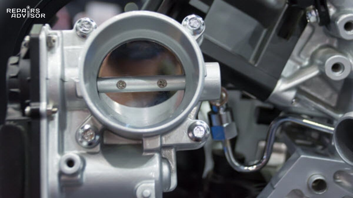
The TPS sits on the throttle body shaft so it can directly monitor the position of the throttle plate at all times. As you press the accelerator, the throttle plate opens — the TPS detects that angle change and sends a corresponding voltage signal to the engine control unit. The ECU uses this real-time feedback as a core input for calculating fuel injection quantity, ignition timing, idle speed control and automatic transmission shift points. A smooth, continuous voltage sweep tells the ECU exactly how aggressively the driver is demanding power. A corrupt signal — flat spots, spikes or dead zones — throws off every one of those calculations simultaneously.
On a standard three-wire TPS, the ECU supplies a 5V reference voltage on one wire, a ground on the second, and reads the variable output on the third. At closed throttle the signal voltage typically reads around 0.5V; at wide-open throttle (WOT) it reaches approximately 4.5V. The ECU also monitors the rate of change — a rapid voltage increase signals hard acceleration and triggers a corresponding fuel enrichment. This is why even minor irregularities in the TPS signal can cause noticeable driveability problems.
Potentiometer vs. Hall Effect TPS
Two main sensor types are used in production vehicles. The potentiometer (contact) type is the most common design, particularly on pre-2010 vehicles. It uses a resistive carbon track and a sliding wiper that physically contacts the track as the throttle shaft rotates. This design works reliably but is vulnerable to wear — the carbon track can develop dead spots over time that produce the erratic voltage drops associated with TPS failure.
The Hall effect (non-contact) type uses a small magnet on the throttle shaft and a stationary sensor that detects changes in magnetic field strength. Because there is no physical contact between moving parts, Hall effect sensors are significantly more durable and are standard on most modern drive-by-wire systems. Many drive-by-wire vehicles also use dual-track sensors — two redundant potentiometers with opposite voltage curves — allowing the ECU to cross-check readings and detect failures that would be invisible to a single-track design.
TPS vs. Accelerator Pedal Position Sensor
A common source of confusion: the TPS and the accelerator pedal position sensor (APPS) are two different components. The APPS is located at the pedal assembly and measures how far the driver has pressed the accelerator. On drive-by-wire vehicles there is no physical cable connecting the pedal to the throttle body — the ECU reads the APPS signal and commands the throttle motor to open the plate to a corresponding angle. The TPS then confirms that the plate actually moved to the commanded position. Problems with the pedal cable rather than the TPS itself present differently; a damaged accelerator cable produces its own distinct set of symptoms worth understanding before diagnosis.
Symptoms of a Bad Throttle Position Sensor
TPS failure rarely announces itself with a single obvious symptom. More commonly it produces a cluster of driveability complaints that seem unrelated until you understand the sensor’s role in the engine management system. The pattern of symptoms — particularly when they correlate with specific throttle positions — is one of the strongest diagnostic clues you have before touching a multimeter.
Driveability Symptoms
Rough or unstable idle. At closed throttle, the ECU relies heavily on the TPS to maintain idle speed. If the sensor sends an erratic signal at low throttle angles, the ECU can’t stabilize fuel delivery and the engine RPM will hunt — rising and falling without driver input. This is one of the most common TPS complaints.
Hesitation or stumble on acceleration. Dead spots in a worn potentiometer track cause momentary voltage drops as the throttle moves through that angle. The ECU interprets a sudden voltage drop as a rapid throttle closure and cuts fuel accordingly — producing a hesitation or stumble right as you’re trying to accelerate. This symptom is often intermittent, which makes it particularly frustrating to diagnose.
Engine surging or unintended acceleration. A corrupt TPS signal can also send a falsely high voltage reading, causing the ECU to inject more fuel than the actual throttle position warrants. The result is surging RPM or a feeling that the vehicle is pulling forward without deliberate throttle input. If this symptom is present, treat it as urgent — stop driving and seek professional diagnosis before continuing to use the vehicle.
Poor fuel economy. When the ECU can’t accurately determine throttle position, it often defaults to richer fuel delivery as a safety margin. The air-fuel ratio runs rich more than necessary, and fuel consumption increases noticeably.
Automatic transmission shift problems. This one surprises many drivers. Shift points in automatic transmissions are calculated using TPS data alongside vehicle speed. A faulty TPS can cause early or late upshifts, harsh gear changes, or in some cases the transmission refusing to shift out of a particular gear.
Diagnostic Trouble Codes
A failing TPS will typically trigger one or more P01XX air and sensor circuit codes. The five most common TPS-related codes are:
P0120 — TPS circuit malfunction. The ECU has detected a voltage reading outside the expected operating range. This code points to a circuit-level problem — the signal wire, reference voltage, or ground circuit may be at fault, not necessarily the sensor itself.
P0121 signals a range or performance issue: the voltage output doesn’t correlate with data from other sensors such as the MAF or MAP. The sensor is producing a signal, but it doesn’t match what the ECU expects given the rest of the sensor network.
P0122 (low input) and P0123 (high input) indicate the signal voltage is stuck at one extreme — either consistently below the minimum, pointing to an open circuit or short to ground, or consistently above the maximum, suggesting a short to the reference voltage circuit.
P0124 flags an intermittent fault where the signal drops out unpredictably — a classic sign of a connector developing corrosion or a potentiometer track with a growing dead spot.
On drive-by-wire vehicles, P2135 indicates a correlation error between the two TPS tracks — the dual sensors are providing readings that don’t agree with each other within the acceptable tolerance. This code almost always requires professional diagnosis.
An important caution: none of these codes prove the TPS itself has failed. They indicate a fault in the TPS circuit, which includes the sensor, its wiring harness and its connector. Replacing the sensor without testing the circuit first is how TPS gets misdiagnosed. Always understand what OBD codes are actually telling you before ordering parts.
Distinguishing TPS Faults from Similar Sensors
Several other sensors produce similar driveability complaints. A failing mass air flow sensor causes hesitation and rough running across all throttle positions, while TPS issues typically appear at specific throttle angles where a dead spot in the track exists. A MAP sensor fault produces similar hesitation but tends to worsen under load rather than at a fixed throttle position. Oxygen sensor faults affect fuel economy and emissions readings but generally don’t cause the pronounced driveability complaints associated with TPS failure. Freeze frame data captured with an OBD scanner — noting the engine RPM, vehicle speed, and throttle percentage when the code set — is invaluable for narrowing this down.
How to Test a Throttle Position Sensor
Accurate diagnosis before replacement saves time, money and the frustration of pulling a working sensor. The process follows four logical steps: read codes, inspect the circuit visually, perform a multimeter voltage test, and confirm findings with live scan tool data.
Step 1 — Read and Record Fault Codes
Connect an OBD-II scanner and record all stored codes plus their freeze frame data. Freeze frame captures the exact engine conditions — RPM, vehicle speed, calculated load, throttle percentage — at the moment the code set. This context often reveals whether the fault occurred at a specific throttle angle (pointing to a dead spot) or across all conditions (pointing to a wiring or power supply issue). Clear the codes, perform a road test, and check whether they return and under what conditions.
Step 2 — Visual Inspection of the Circuit
Before reaching for a multimeter, spend two minutes inspecting the TPS connector and wiring harness. Disconnect the connector and examine the pins for corrosion, green oxidation, bent terminals or cracked housing. Check the wiring harness for chafing against sharp edges, heat damage near exhaust components, or oil contamination that can wick into the connector. With the engine running, gently wiggle the connector — any RPM fluctuation confirms a connection issue that will persist regardless of whether you replace the sensor.
Step 3 — Multimeter Voltage Test
This is the definitive test for a potentiometer-type TPS. You’ll need a digital multimeter, back-probe pins or T-pins to access the connector without disconnecting it, and your vehicle’s wiring diagram to identify the three wires. Set the multimeter to DC voltage mode. Turn the ignition to ON without starting the engine — this powers the TPS circuit.
Identify the signal output wire (the center wire in most three-pin connectors, but verify with your wiring diagram). Connect the red probe to the signal wire and the black probe to a good chassis ground. With the throttle fully closed, you should read approximately 0.5V. Now slowly and smoothly open the throttle by hand from fully closed to fully open while watching the multimeter display.
The voltage should rise in a smooth, linear sweep from about 0.5V to approximately 4.5V with no interruptions. Any sudden drops, spikes, or flat sections where the voltage doesn’t change despite continued throttle movement indicate a worn or damaged potentiometer track. These dead zones are the primary failure mode of contact-type TPS sensors. A sensor showing flat spots or dropout should be replaced regardless of whether it’s currently storing a code.
Step 4 — Live Data Confirmation
If your scanner supports live data, monitor the TPS percentage and voltage alongside MAF g/s and MAP kPa during a road test. A healthy TPS produces a clean, proportional curve that tracks throttle input without hesitation or dropout. Cross-referencing TPS data against MAF and MAP readings helps confirm whether the TPS is the root cause or whether another sensor — a failing coolant temperature sensor, for instance — is corrupting the fuel calculation from a different direction. If TPS percentage matches throttle movement but MAP readings are erratic, the problem may lie elsewhere.
How to Replace a Throttle Position Sensor
On most vehicles with a traditional standalone TPS, replacement is a straightforward job that requires only basic hand tools and a multimeter for post-installation verification. The main variable is whether your vehicle has an integrated sensor — common on modern drive-by-wire throttle bodies — which changes the scope of the repair considerably.
Parts and Tools
Before starting, source a replacement sensor. OEM sensors from the vehicle manufacturer cost $100–$300 but provide the most reliable fit and calibration. Quality aftermarket sensors from established brands — Denso, NTK/NGK, Delphi, Bosch — perform comparably at $25–$100. Avoid unbranded budget sensors; signal accuracy on this particular component directly affects fuel delivery and emissions.
Tools needed: digital multimeter, Phillips and flathead screwdrivers, socket set (vehicle-dependent), OBD-II scanner for clearing codes and performing the relearn procedure, and dielectric grease for the connector on reassembly. Total shop cost for professional replacement typically runs $120–$280, with labor accounting for most of the difference from DIY cost.
Replacement Procedure
Always consult your vehicle-specific repair manual before beginning. The steps below outline the general procedure for a standalone external TPS on a traditional throttle body. Procedures vary by vehicle — torque specifications, sensor orientation, and connector release mechanisms differ across makes and models.
- Disconnect the negative battery terminal and wait at least two minutes before working on any electrical components.
- Locate the TPS on the throttle body — it is mounted on the throttle shaft, typically on the opposite side from the throttle return spring.
- Disconnect the electrical connector by pressing the release tab carefully. Broken release tabs are a common avoidable frustration.
- Remove the two mounting screws. Note the sensor’s orientation relative to the throttle shaft before removal, as some sensors must be reinstalled at a specific alignment.
- Slide the old sensor off the throttle shaft. Inspect the shaft and mounting surface for wear, corrosion or debris.
- Slide the new sensor onto the shaft in the correct orientation — some are keyed and only fit one way; others require careful alignment to achieve the correct closed-throttle voltage. Reinstall and snug the mounting screws without overtightening, as the sensor housing is plastic.
- Reconnect the electrical connector until it clicks. Apply a small amount of dielectric grease to the pins to prevent future corrosion.
- Reconnect the negative battery terminal.
Important: On drive-by-wire systems, the TPS is often built into the throttle body assembly itself. In these cases, replacing the TPS means replacing the entire throttle body — a job that is within reach for experienced DIYers but involves additional steps including removing intake ducting, disconnecting vacuum lines, and torquing the throttle body to the intake manifold with a fresh gasket. The specific procedure for your vehicle — whether Ford, Toyota, Honda or Chevrolet — will be detailed in your vehicle’s factory service manual.
ECU Relearn and Calibration After Replacement
Replacing the TPS without completing the relearn procedure is one of the most common post-repair mistakes. The ECU stores a learned baseline — the voltage it considers “closed throttle” and the full sweep range — for the specific sensor it has been working with. Install a new sensor and the ECU is still operating with the old sensor’s learned values. The result is typically rough idle, hesitation, erratic throttle response, or in some cases limp mode.
Manual Relearn (Older Vehicles)
Many pre-2010 vehicles support a basic battery-disconnect relearn. Disconnect the negative battery terminal for 10–15 minutes to clear the ECU’s adaptive memory. Reconnect, turn the ignition to ON without starting, and wait for the dash warning lamps to complete their initialization cycle. Slowly press the accelerator pedal to the floor and release fully — repeat two to three times smoothly, without pumping. Start the engine and allow it to idle undisturbed for five minutes while the ECU relearns the idle control parameters. This method works reliably on many older platforms but provides no confirmation of success.
Scan Tool Relearn (Modern Vehicles)
Most modern vehicles — particularly those with drive-by-wire throttle bodies or complex engine management systems — require a bidirectional scan tool to initiate the throttle adaptation procedure. Generic OBD-II readers can read codes but typically cannot run service functions. Tools such as the Autel MaxiCOM series, Launch X431 or Foxwell NT510 support manufacturer-specific relearn routines. Navigate to Special Functions or Service Functions, select Throttle Valve Adaptation or Throttle Body Relearn, and follow the on-screen procedure. The process typically takes three to five minutes and usually provides a pass/fail confirmation. Clear any stored fault codes after the relearn is complete and perform a short road test to verify smooth idle and throttle response.
TPS Lifespan, Maintenance and When to Consult a Professional
The throttle position sensor has no scheduled replacement interval in any manufacturer’s maintenance program. Most sensors last well beyond 80,000–100,000 miles; failure is typically driven by wear in the potentiometer track, contamination, connector corrosion, or heat and vibration damage. There is no preventive replacement to perform — the TPS is replaced when it fails.
That said, two maintenance practices extend TPS service life. First, keep the throttle body clean. Carbon buildup on the throttle plate bore affects how the plate seats at idle, which changes the closed-throttle position the TPS needs to report accurately. A clean air intake reduces carbon accumulation; maintaining a clean, properly seated air filter is the most effective prevention step. Second, inspect the TPS connector during other maintenance work. Apply fresh dielectric grease if you see early signs of oxidation on the pins. Connector corrosion causes intermittent faults that are far harder to diagnose than sensor failures, and they take less than two minutes to prevent.
There are scenarios where professional diagnosis is the right call rather than DIY. If symptoms persist after sensor replacement and a completed relearn procedure, the fault may lie in the wiring harness, the ECU reference voltage circuit, or in the ECU itself — a substantially more complex diagnostic path. P2135 dual-sensor correlation errors on drive-by-wire vehicles almost always require a professional scan tool and the kind of circuit-level testing that goes beyond what most DIYers are equipped for. Most importantly: if your vehicle is exhibiting sudden, uncontrolled acceleration, stop driving immediately. This is not a symptom to diagnose while continuing to use the vehicle — it is a safety issue requiring immediate professional attention.
For vehicles where the TPS is integrated into the throttle body or where manufacturer-specific relearn procedures are not supported by a generic scan tool, having access to a factory-level service manual for your specific make and model is essential. Understanding your vehicle’s exact system before beginning any repair prevents the kind of misdiagnosis that turns a $60 part into a $600 problem.
Throttle Position Sensor: Frequently Asked Questions
The throttle position sensor (TPS) is one of those components most drivers never think about until it causes problems — and then it causes a lot of problems all at once. These answers address the most common questions about TPS function, symptoms, diagnosis, and repair, drawing on the same technical detail covered in our full throttle position sensor guide.
Quick Answer
The throttle position sensor (TPS) monitors the angle of the throttle plate and sends a voltage signal (typically 0.5V at idle to 4.5V at wide-open throttle) to the ECU to control fuel injection and ignition timing. When it fails, common symptoms include rough idle, hesitation, engine surging, and check engine codes P0120–P0124. Most vehicles require an ECU relearn after replacement.
What does a throttle position sensor do?
The TPS sits on the throttle body shaft and monitors the exact angle of the butterfly valve at all times. As you press the accelerator, the valve opens — the sensor converts that physical angle into a variable voltage signal and sends it to the engine control unit. The ECU uses this signal to calculate how much fuel to inject, when to fire the ignition, how to manage idle speed, and when to shift in an automatic transmission. It also tracks the rate of change: a rapid voltage increase tells the ECU you’re accelerating hard and triggers fuel enrichment accordingly. Understanding how the ECU uses sensor inputs makes clear why even a minor TPS irregularity can disrupt engine behaviour across multiple systems simultaneously.
What are the most common symptoms of a bad throttle position sensor?
Five symptoms come up most consistently. Rough or unstable idle — the engine RPM hunts up and down without any throttle input, because the ECU can’t stabilise fuelling at closed throttle. Hesitation or stumble on acceleration — a characteristic flat spot caused by dead zones in a worn potentiometer track. Engine surging or unintended acceleration — the ECU receives a falsely high voltage and over-injects fuel, producing unexpected forward pull. Poor fuel economy — the ECU defaults to richer fuelling when it can’t accurately determine throttle position. Automatic transmission shift problems — shift points are TPS-dependent, so a faulty sensor causes early, late, or harsh gear changes. A check engine light accompanies most of these scenarios. The pattern of symptoms — especially when they tie to a specific throttle angle — is a valuable diagnostic clue before reaching for a test tool.
Can you drive with a bad throttle position sensor?
Technically yes, but it is not advisable beyond getting the vehicle to a safe location or repair shop. A degraded TPS that is producing erratic readings can cause unpredictable engine behaviour — stalling in traffic, hesitation during lane changes, or in more severe cases, unintended acceleration when the sensor sends a falsely high voltage reading. Many modern vehicles will enter limp mode when a TPS fault is detected, which restricts engine output and limits available gears to protect the drivetrain. Limp mode is driveable for short distances but is not intended as a long-term operating state. If you experience sudden, uncontrolled acceleration, stop the vehicle safely and immediately — do not attempt to diagnose this symptom on the road.
What OBD codes does a bad TPS trigger?
The most common TPS-related diagnostic trouble codes are P0120 (TPS circuit malfunction — voltage outside expected range), P0121 (range/performance — signal doesn’t correlate with MAF or MAP data), P0122 (circuit low input — voltage stuck below minimum), P0123 (circuit high input — voltage stuck above maximum), and P0124 (intermittent fault — signal dropping out unpredictably). On drive-by-wire vehicles with dual-track sensors, P2135 indicates a correlation error between the two sensor tracks. An important caveat: these codes point to a fault in the TPS circuit, not necessarily a failed sensor — the wiring harness, connector pins, or the ECU reference voltage supply could be the actual cause. Understanding how to properly read OBD codes and capturing freeze frame data is essential before ordering parts. The P01XX code family covers air and sensor circuit faults in broader detail.
How do you test a throttle position sensor?
The standard test uses a digital multimeter in DC voltage mode. With the ignition ON and engine OFF, back-probe the signal wire (centre wire on most three-pin connectors — verify with your wiring diagram). The red probe goes to the signal wire, the black to chassis ground. At closed throttle you should read approximately 0.5V; slowly open the throttle to wide-open and the voltage should rise in a smooth, linear sweep to approximately 4.5V with no interruptions. Any sudden drops, spikes, or flat sections where voltage stalls despite continued throttle movement indicate a worn potentiometer track. The static test catches dead spots, but intermittent faults that only appear under load can slip through. Pairing it with live scan tool data during a road test — monitoring TPS percentage in real time and cross-referencing against MAP sensor output — closes that gap and confirms whether the TPS is the root cause or another sensor is corrupting the circuit.
Can you clean a throttle position sensor instead of replacing it?
For a potentiometer-type TPS, cleaning doesn’t address the underlying failure mode. The most common failure in contact-type sensors is mechanical wear on the resistive carbon track — the sliding wiper physically erodes the track over millions of throttle cycles, creating dead zones in the voltage output. No amount of cleaning restores a worn track. What you can usefully clean is the throttle body itself: carbon buildup around the throttle bore affects how the plate seats at idle, which changes the baseline position the TPS must report. A clean throttle body removes a variable that can mimic TPS symptoms, and is worth doing before condemning the sensor if you haven’t eliminated it as a cause. If connector corrosion is generating an intermittent fault code, cleaning the terminals with electrical contact cleaner and applying dielectric grease may resolve the issue without replacement — but a worn sensor will need to be replaced.
How much does it cost to replace a throttle position sensor?
Parts cost varies significantly by sensor type. A standalone external TPS on an older cable-operated throttle body runs $25–$100 for a quality aftermarket unit (Denso, NTK/NGK, Delphi, or Bosch) or $100–$300 for OEM. On modern drive-by-wire vehicles where the TPS is integrated into the throttle body assembly, the entire throttle body must be replaced — a substantially higher parts cost. Labour for a standalone sensor is typically 30–60 minutes; an integrated throttle body swap takes 1–2 hours. Total professional replacement cost for a standalone sensor generally runs $120–$280 depending on the shop and location. Avoid the cheapest unbranded sensors — accuracy matters on this component, and a sensor with poor signal linearity will cause the same driveability complaints as the one it replaced. Always confirm the actual sensor is faulty via circuit testing before authorising the repair, as misdiagnosis of TPS faults is common.
Do you need to recalibrate the ECU after replacing a TPS?
Yes — skipping this step is one of the most common post-replacement mistakes. The ECU stores learned throttle position parameters: what voltage corresponds to true zero throttle and what the full sweep range looks like. After installing a new sensor, those stored values no longer match the new sensor’s output. Without a relearn, you may experience rough idle, hesitation, or in some cases limp mode even with a fully functional new sensor installed. On many older vehicles, a basic relearn can be initiated by disconnecting the battery for 10–15 minutes, reconnecting, then performing a slow full-throttle sweep with the ignition on and engine off, followed by a 5-minute idle. Modern vehicles — particularly those with drive-by-wire throttle bodies — require a bidirectional scan tool to run the manufacturer’s Throttle Valve Adaptation or Throttle Body Relearn procedure. Generic code readers cannot do this; you need a tool that supports the service functions menu for your specific make. Always check your vehicle’s repair manual for the exact procedure — the Toyota, Ford, Honda, and Chevrolet relearn sequences are each different.
How long does a throttle position sensor last?
There is no manufacturer-scheduled replacement interval for the TPS — it is a replace-on-failure component. Most sensors outlast 80,000–100,000 miles before developing problems, though service life depends heavily on sensor type and operating environment. Contact-type potentiometers wear mechanically over time and tend to fail sooner on vehicles with frequent stop-start driving cycles. Hall effect sensors, common on modern drive-by-wire systems, have no moving contact surfaces and typically last considerably longer. Premature failure is often caused by connector corrosion from water or oil ingress, heat damage from proximity to exhaust components, or wiring harness chafing. Keeping the air filter clean and serviced reduces carbon deposits in the throttle body, which indirectly protects the TPS alignment and reduces wear on the sensor’s zero-position reference.
Is the throttle position sensor the same as the accelerator pedal position sensor?
No — they are two different sensors with different locations and functions, though they work together on drive-by-wire vehicles. The accelerator pedal position sensor (APPS) is mounted at the pedal assembly and measures how far the driver has pressed the accelerator. On cable-operated throttle systems, a physical cable transmits that pedal movement directly to the throttle body. On drive-by-wire systems, there is no cable — the ECU reads the APPS signal electronically and commands a throttle motor to open the plate to the corresponding angle. The TPS then confirms the throttle plate actually moved to the commanded position. Faults in the APPS produce different codes (typically P2135, P2138 or P-APPS specific codes) and different symptom patterns compared to TPS faults. Accelerator cable issues on older vehicles have their own distinct diagnostic signature as well.
What’s the difference between a TPS fault and a MAF sensor fault?
Both sensors influence fuel delivery and can produce overlapping symptoms — hesitation, rough running, and check engine lights — but they fail differently and affect the engine at different operating points. A MAF sensor fault tends to affect performance across all throttle positions, because the mass air flow sensor measures total intake air volume at all times. A TPS fault with a dead spot in the potentiometer track typically causes symptoms at a specific throttle angle — the vehicle may run smoothly at idle and at steady cruise but stumble badly through the precise range where the worn section of the track sits. MAF faults also commonly trigger lean codes (P0171, P0174) because the ECU underestimates airflow and under-injects fuel; TPS faults are more likely to cause rich conditions or erratic fuel calculations. If freeze frame data shows the fault code set at a consistent throttle percentage, TPS is the stronger suspect. If the code sets randomly across operating conditions, investigate the MAF circuit first. The fuel injection system relies on both sensors working accurately — when one is compromised, the other’s data alone isn’t enough to fully compensate.
What happens if you ignore a bad throttle position sensor?
Ignoring a failing TPS typically leads to progressively worse symptoms, and in some cases, cascading damage. Poor air-fuel ratio control caused by a corrupt TPS signal accelerates wear on catalytic converter substrates — the converter is designed for a narrow air-fuel band, and persistent rich or lean conditions shorten its service life considerably. In vehicles where the faulty TPS prevents efficient combustion, excess fuel can wash cylinder walls and dilute engine oil. Beyond component damage, the driveability symptoms — hesitation, surging, unpredictable throttle response — create real road safety risks, particularly in traffic requiring precise throttle control. The check engine light will prevent the vehicle from passing emissions testing in jurisdictions that require it. A TPS is not an expensive repair compared to the systems it can damage when left unaddressed.