The crankshaft position sensor — often abbreviated CKP, CPS, or CAS — is one of the most important sensors in a modern engine. Every time your engine fires a spark plug or squirts fuel into a cylinder, it’s because the ECU consulted the crankshaft position sensor first. Without an accurate signal from this sensor, the engine management system is essentially flying blind, which is why a failed CKP sensor is one of the most common causes of a crank-but-no-start condition. Understanding how this sensor works, what symptoms to look for, and how to diagnose and replace it can save you significant diagnostic time and money.
Quick Answer
The crankshaft position sensor monitors the rotational speed and position of the crankshaft, sending this data to the ECU to control ignition timing and fuel injection. When it fails, common symptoms include engine won’t start, intermittent stalling, misfires, poor acceleration, and a Check Engine light with codes P0335–P0339. Replacement costs $30–$115 for the part alone; professional labour brings the total to $150–$500 for most vehicles. Most DIYers with basic tools can replace an externally-mounted sensor; note that some vehicles require a crankshaft relearn procedure after installation.
What Is a Crankshaft Position Sensor?
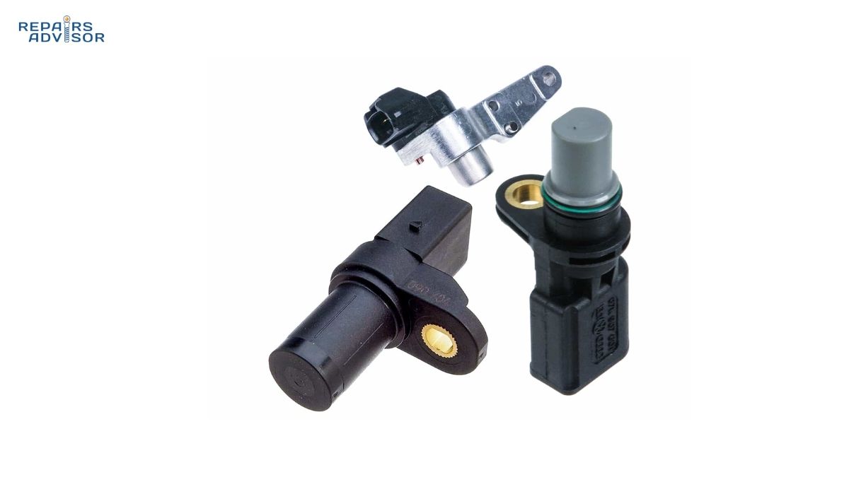
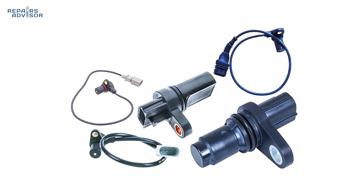
The crankshaft position sensor is an electronic sensor mounted near the crankshaft, harmonic balancer, or flywheel. Its job is to monitor two things simultaneously: the exact rotational position of the crankshaft at any given moment, and how fast that crankshaft is spinning — in other words, engine RPM.
This information flows directly to the engine control unit (ECU), which uses it to determine precisely when to fire each spark plug and when to pulse each fuel injector. Get the timing wrong by even a few degrees and you get misfires, poor fuel economy, and sluggish performance. Get it wrong enough and the engine won’t run at all.
Depending on the manufacturer and service manual, you may see it called a CKP sensor, CPS, crank angle sensor (CAS), engine speed sensor (ESS), or crankshaft reference sensor — all different labels for the same component.
In modern engines, the CKP sensor works hand-in-hand with the camshaft position sensor to identify which specific cylinder is on its compression stroke — a critical piece of information needed to sequence fuel injectors correctly and to synchronise the ignition system. The crankshaft sensor handles speed and gross position; the camshaft sensor pins down the exact combustion phase. Together they give the ECU a complete picture of what every piston in the engine is doing at any moment.
How the Crankshaft Position Sensor Works
The Reluctor Wheel
The heart of the CKP sensor system is the reluctor wheel, also called a tone ring or trigger wheel. This is a toothed metal disc bolted to the crankshaft, harmonic balancer, or flywheel — it spins at exactly the same speed as the crankshaft. As the engine runs, the teeth on this wheel pass close to the tip of the sensor, creating a changing magnetic field that generates an electrical signal.
There’s a deliberate gap in the reluctor wheel’s tooth pattern — one slot is intentionally absent. This “missing tooth” acts as a reference point, telling the ECU exactly where the crankshaft is in its rotation cycle and identifying Top Dead Centre (TDC) for the reference cylinder. Without this reference, the ECU would know how fast the engine is spinning but not where each piston is in its stroke.
Understanding this mechanism helps explain why a damaged reluctor wheel — one with missing, chipped, or dirty teeth — can produce the same fault codes as a failed sensor. The sensor is fine; the wheel it’s reading from is not.
Two Types of CKP Sensors: VR vs Hall Effect
Not all crankshaft position sensors work the same way. There are two distinct technologies in use, and knowing which type your vehicle has matters because testing procedures differ between them.
Variable Reluctance (VR) sensors are the older, simpler design. They use a permanent magnet and a coil of wire. As each tooth on the reluctor wheel passes the sensor tip, it disturbs the magnetic field and induces a small voltage in the coil — the sensor generates its own signal without needing external power. This is why VR sensors typically have only two wires: signal and ground. The signal is an analogue AC sine wave that gets stronger and faster as engine speed increases. At very low RPM — under about 50 RPM — the signal can be too weak for the ECU to read accurately, which is one limitation of this design.
Hall effect sensors are the modern standard. They use a semiconductor chip that responds to changes in a magnetic field, outputting a clean digital square wave signal regardless of engine speed. Unlike VR sensors, Hall effect sensors require power to operate — they typically have three wires: a 5-volt reference supply, a ground, and the signal output wire. Because the digital output is consistent from the first crank rotation, Hall effect sensors are more accurate at low RPM and easier for ECUs to process. Most vehicles made in the last decade use this type.
A quick way to identify which type you have: count the connector wires. Two wires typically indicates a VR sensor; three or four wires typically indicates a Hall effect sensor. When in doubt, consult your vehicle’s service manual or wiring diagram before testing.
The ECU Connection
The CKP signal feeds continuously to the ECU while the engine runs. From this stream, the ECU derives crankshaft angle, engine RPM, and each piston’s position relative to TDC — the three values that govern everything downstream.
These values directly govern ignition timing — the ECU uses them to trigger the ignition coils, firing each spark plug at the precise moment combustion will be most efficient. They also govern fuel delivery — the fuel injection system uses CKP data to time each injector pulse. Sensor inputs from the manifold absolute pressure (MAP) sensor and other load sensors work alongside the CKP data to determine how much fuel to inject; the CKP data determines when.
Common Sensor Locations
The CKP sensor’s physical location varies significantly by engine design, and location has a big impact on replacement difficulty.
The most common location is near the front of the engine at the harmonic balancer or main crankshaft pulley. This is generally the most accessible position — the sensor bolts into the engine block or timing cover and the reluctor wheel is on the harmonic balancer. Most intermediate DIYers can reach the sensor without significant disassembly.
On some engines, the sensor is positioned at the flywheel or flexplate at the rear of the engine, near the transmission bell housing. This location is far more difficult to access — it may require removing the starter, heat shields, or other components to reach the sensor and connector. Labour time and cost increases substantially for bell-housing-mounted sensors.
A minority of engine designs mount the sensor inside the engine block itself, reading directly off the crankshaft. These are the most difficult to service and almost always warrant professional replacement.
Always locate your specific sensor before purchasing parts and before estimating whether this is a DIY job. The service manual for your vehicle is the most reliable source for exact location and access procedure — vehicle-specific manuals are available for a wide range of makes including Ford, Toyota, and Nissan.
Symptoms of a Failing Crankshaft Position Sensor
CKP sensor failure can be intermittent at first, making diagnosis frustrating. Symptoms may come and go depending on engine temperature, vibration, or connector condition. As the sensor deteriorates further, symptoms become more consistent and eventually lead to a no-start condition.
1. Engine Won’t Start (Crank-No-Start)
A complete CKP sensor failure typically results in a crank-no-start condition: the starter motor spins the engine normally, but the engine won’t fire. This happens because the ECU isn’t receiving a signal indicating crankshaft rotation, so it refuses to trigger spark or fuel injection. A useful diagnostic clue: watch the tachometer while cranking. If the needle stays at zero — even while you can hear and feel the engine cranking — the ECU is not seeing a CKP signal, which points strongly toward a sensor or wiring fault.
2. Intermittent Stalling
Intermittent stalling, especially while driving at speed, is a classic early-stage CKP failure symptom. When the sensor signal drops out momentarily, the ECU loses its timing reference and cuts power to the engine. The vehicle may restart after pulling over and waiting — sometimes because the engine has cooled and a heat-damaged sensor temporarily recovers. This pattern of stalling that clears after cooldown is a strong indicator of a thermally-failing CKP sensor.
3. Engine Misfires and Rough Running
An inaccurate or intermittent CKP signal causes mistimed spark delivery, which in turn causes cylinder misfires. You’ll feel this as a rough idle, hesitation under acceleration, or a subtle but persistent stumble. Keep in mind that misfires have many causes — worn spark plugs and failing ignition coils are far more common culprits — so always check fault codes before assuming the CKP sensor is responsible.
4. Check Engine Light with CKP Fault Codes
A malfunctioning CKP sensor almost always triggers the Check Engine light and stores one or more diagnostic trouble codes in the ECU. The primary codes to look for are in the P03XX code range:
- P0335 — Crankshaft Position Sensor “A” Circuit Malfunction (most common)
- P0336 — CKP Sensor “A” Circuit Range/Performance
- P0337 — CKP Sensor “A” Circuit Low Input
- P0338 — CKP Sensor “A” Circuit High Input
- P0339 — CKP Sensor “A” Circuit Intermittent
P0335 is notably more prevalent in Toyota, Nissan, Audi, and Dodge models — manufacturers where the sensor is often mounted in heat-exposed locations that accelerate failure. If you own one of these makes and are experiencing any of the symptoms described here, a CKP-related fault code deserves early consideration in the diagnostic process.
5. Poor Acceleration and Reduced Fuel Economy
When the CKP sensor is delivering inaccurate but not completely absent data, the ECU’s fuel and ignition timing calculations go off. You may notice sluggish acceleration, reduced power under load, or a noticeable drop in fuel economy. The mass air flow sensor and other load sensors still provide their inputs, but without accurate crankshaft timing data, the ECU can’t execute optimal combustion events.
6. Engine Enters Limp Mode
Some ECUs detect a degraded CKP signal and deliberately restrict engine performance as a protective measure — reducing maximum RPM and power output while still allowing limited driving. If your vehicle suddenly feels severely underpowered with no obvious cause, limp mode triggered by a sensor fault is worth investigating.
Common Causes of CKP Sensor Failure
Understanding why CKP sensors fail helps you make smart decisions at purchase time and during installation.
Heat damage is the leading cause on many vehicles. The sensor lives in a hot, vibration-heavy environment near the engine block, and sustained high temperatures degrade the internal electronics and the housing over time. Sensors mounted near exhaust manifolds or in tight, poorly-ventilated engine bays are particularly vulnerable.
Oil contamination is another common failure mode. A leaking crankshaft front seal or valve cover gasket can saturate the sensor and its connector with oil, degrading the electrical connections and eventually the sensor itself.
Wiring and connector damage causes many apparent “sensor failures” that are actually wiring problems. The harness between the sensor and ECU runs through a hot, vibrating engine bay — wires can chafe against brackets, crack from heat cycling, or corrode at connector pins, especially in humid climates. A damaged wire produces the same fault codes as a dead sensor.
Reluctor wheel damage produces the same symptoms as sensor failure but requires a different repair. Chipped or missing teeth on the reluctor ring cause the ECU to see an irregular signal pattern, triggering P0336 (range/performance) codes and causing misfires or stalling. If the sensor tests normal but symptoms persist, inspect the reluctor wheel itself.
High-mileage wear eventually affects every sensor. The internal coil and electronic components have a finite service life; beyond 150,000–200,000 miles, spontaneous failure becomes increasingly likely.
How to Diagnose a Crankshaft Position Sensor
Accurate diagnosis before purchasing parts is essential — CKP sensor symptoms overlap significantly with fuel system, ignition system, and even ECU faults. The following procedure applies to intermediate DIYers with basic scan tool access. For vehicles with sensors requiring significant disassembly to reach, professional diagnosis is more practical.
Step 1: Scan for Fault Codes
Connect an OBD-II scanner and retrieve all stored fault codes. Look for P0335 through P0339 as primary indicators, and note any secondary codes that might point to related systems. Review freeze frame data — the conditions recorded at the moment the fault triggered (engine temperature, RPM, load) can help distinguish an intermittent fault from a hard failure.
With the scanner connected, attempt to start the engine and watch the live RPM reading during cranking. A healthy CKP sensor should produce an RPM reading of 100–500 RPM while the starter is engaged. If the RPM display stays at zero during cranking, the ECU is receiving no signal — a strong indication of sensor or wiring failure.
Step 2: Visual Inspection
Before any electrical testing, inspect the sensor visually. Check the sensor body for cracks, heat discolouration, or oil fouling. Inspect the electrical connector for bent pins, corrosion, or a loose fit — connectors that feel easy to disconnect may not be making solid contact. Trace the wiring harness from the sensor toward the firewall, looking for chafing against metal brackets, cracked insulation, or obvious damage from heat.
If the reluctor wheel is visible without disassembly, inspect it for missing, chipped, or heavily corroded teeth. Even one missing tooth can cause intermittent misfires and range/performance codes.
Step 3: Multimeter Testing
Testing procedure depends on sensor type. For a VR sensor (2-wire), disconnect the sensor connector, set the multimeter to ohms, and measure resistance between the two sensor pins. Most VR sensors read 200–2,000 ohms when healthy — check your vehicle’s service manual for the specific OEM specification, as it varies. Infinity (open circuit) means a broken internal wire; zero ohms means a short. You can also test signal output: set the multimeter to AC voltage, reconnect the sensor, and have an assistant crank the engine while you monitor the signal pin. A healthy sensor produces 0.5–5V AC during cranking.
For a Hall effect sensor (3-wire), verify the power supply first: with the ignition ON (engine off), check voltage between the power and ground pins — you should see approximately 5V. Confirm ground continuity between the ground pin and chassis. To check signal output, monitor the signal wire with the ignition ON while slowly rotating the crankshaft by hand (or have the engine cranked briefly) — a working Hall effect sensor switches cleanly between low and high voltage as teeth pass.
Keep in mind that a resistance test only confirms no broken wire — it doesn’t verify that the sensor and reluctor wheel are working together correctly under operating conditions. If results are borderline, the next step gives more definitive answers.
Step 4: Live Data and Oscilloscope Testing
A scan tool’s live data graph mode is the most practical way to observe CKP sensor behaviour during actual engine operation. A healthy sensor produces a consistent waveform that rises and falls proportionally with engine speed. Sudden drops to zero, irregular gaps in the signal, or excessive noise all indicate sensor or wiring problems. This is also how you can catch intermittent failures that don’t show during static testing — a fault that only appears at operating temperature will reveal itself on a live data graph during a road test.
An oscilloscope gives the most detailed view of signal quality, showing the actual waveform shape. Professional-grade automotive oscilloscopes can distinguish between a sensor problem, a reluctor ring problem, and a wiring issue by the specific shape of the waveform anomaly. If diagnosis remains inconclusive after scan tool testing, or if the sensor location requires significant disassembly to access, professional diagnosis is the most practical path forward.
Crankshaft Position Sensor Replacement
Is This a DIY Job?
For many vehicles, yes — particularly when the sensor is located at the harmonic balancer or front of the engine and accessible without removing major components. An intermediate DIYer with a basic socket set, a multimeter, and the vehicle’s service manual can typically complete the job in under an hour.
Professional service is worth considering in several situations: the sensor is at the bell housing or inside the engine block; the mounting bolt is corroded and may require extraction; the vehicle requires a post-replacement relearn procedure that demands a dealer-level scan tool; or initial diagnosis remains inconclusive despite testing.
Parts and Costs
The sensor itself typically costs $30–$115 for most mainstream vehicles. Quality matters significantly here — budget sensors from unknown suppliers often fail prematurely, turning a one-time repair into a repeat job. OEM-equivalent or reputable aftermarket parts from established suppliers are worth the modest price difference.
For professional installation, expect total costs (parts plus labour) of $150–$500 for a straightforward, accessible sensor. Bell-housing or block-mounted sensors requiring substantial disassembly can push the total to $600–$800 or more at typical workshop rates.
Basic Replacement Procedure
This is a general guide for an accessible, externally-mounted sensor. Always consult the service manual for your specific vehicle before beginning, as location, fastener sizes, and any air gap requirements vary.
- Disconnect the battery negative terminal. Sensors are electrical components — working hot risks ECU damage and personal injury.
- Locate the sensor and photograph its position and connector orientation before touching anything.
- Disconnect the electrical connector. Most use a locking tab — press the tab while pulling the connector body, not the wires.
- Remove the mounting bolt (typically one bolt, 8–10 mm). If the bolt is corroded and won’t move, penetrating oil and patience are required before applying force.
- Extract the sensor straight out of its bore. Do not pry against aluminium timing covers or engine block faces.
- Clean the mounting hole and surrounding area with a clean rag.
- Compare the new sensor to the old one side-by-side and confirm they match in length, connector position, and body diameter.
- Install the new sensor. If an air gap specification exists for your engine, set it according to the service manual. Apply anti-seize compound to the mounting bolt thread and torque to the manufacturer’s specification.
- Apply dielectric grease to the connector pins, then reconnect. You should feel or hear a positive click from the locking tab.
- Reconnect the battery. Start the engine and confirm the fault code has cleared. If the code returns immediately, the problem is elsewhere — wiring, reluctor ring, or another component.
Safety note: Always verify that the battery is disconnected before handling sensor wiring. Use jack stands, not just a floor jack, if the vehicle needs to be raised for access.
Post-Replacement: The Relearn Procedure
This is a step many DIY guides omit, and skipping it on vehicles that require it can leave you with persistent misfires, rough idle, or fault codes even after a successful sensor installation.
Some ECUs — particularly in GM, Chrysler/Dodge, and certain Ford and Nissan models — need to re-correlate the crankshaft and camshaft sensor references after a CKP sensor is replaced. This process, called a crankshaft relearn or crank variation relearn, allows the PCM to learn the precise relationship between the new sensor’s output and the engine’s actual timing. Without it, the PCM may be working from outdated calibration data that doesn’t match the new sensor’s signal.
The procedure varies by make and model: some require a specific drive cycle, some can be performed using a compatible OBD-II scan tool with relearn functions, and some require a dealer-level diagnostic tool. Before starting the replacement job, research whether your specific vehicle and model year requires a relearn — this determines whether you’ll need additional tools or a shop visit after installation.
CKP Sensor vs. Camshaft Position Sensor: Key Differences
These two sensors are closely related and often confused, especially since faults in one can produce codes pointing toward the other. Understanding the distinction helps narrow down diagnosis when both sensors are implicated.
The crankshaft position sensor reads the crankshaft’s speed and position — it’s the primary timing reference for both ignition and fuel injection. The camshaft position sensor reads the camshaft’s position and identifies the specific combustion phase (intake vs. compression stroke). The ECU uses both together for precise cylinder identification and to control variable valve timing systems where fitted.
In practical terms: a failed CKP sensor typically prevents the engine from starting or causes severe performance issues, because it’s the primary timing reference. A failed CMP sensor on many engines allows the engine to run — though poorly — because the ECU can fall back to a default timing strategy using CKP data alone. Both sensors are monitored against each other; a significant divergence between their signals triggers correlation fault codes (like P0016/P0017) pointing to timing chain or belt problems rather than sensor failure.
Conclusion
The crankshaft position sensor is a small component with an outsized role in engine operation. When it begins to fail, the consequences range from frustrating intermittent symptoms to a complete no-start. The good news is that diagnosis is methodical and accessible — a basic OBD-II scanner and a multimeter are enough to confirm or rule out the sensor in most cases.
For intermediate DIYers, sensor replacement is a manageable job on most vehicles where the sensor sits at the front of the engine. Use OEM-quality parts, confirm whether your vehicle requires a relearn procedure before starting, and consult the service manual for your specific make and model. Vehicle-specific repair documentation makes a genuine difference here — access the right manual for your vehicle on the Ford, Toyota, or Nissan pages, or browse by vehicle category. When diagnosis is uncertain, sensor access is difficult, or a relearn tool is needed, a professional mechanic is the most efficient path to a lasting repair.
Crankshaft Position Sensor: Frequently Asked Questions
The crankshaft position sensor is one of the most searched engine components — and for good reason. When it fails, the symptoms are alarming and the diagnosis isn’t always straightforward. These answers cover the most common questions: how the CKP sensor works, what symptoms to expect, how to diagnose it, and what replacement involves.
Quick Answer
The crankshaft position sensor (CKP or CPS) monitors crankshaft speed and position, feeding that data to the ECU to control ignition timing and fuel injection. Failure symptoms include crank-no-start, stalling, misfires, and fault codes P0335–P0339. Replacement parts cost $30–$115; professional labour brings the total to $150–$500. Some vehicles require a crankshaft relearn procedure after replacement.
What Does a Crankshaft Position Sensor Do?
The crankshaft position sensor monitors two things: the exact rotational position of the crankshaft and its rotational speed in RPM. This data streams continuously to the engine control unit (ECU), which uses it to determine when to fire each spark plug and when to pulse each fuel injector. It’s the primary timing reference for the entire engine — without it, the ECU can’t coordinate spark or fuel delivery, which is why complete sensor failure typically results in a no-start condition.
What Are the Symptoms of a Bad Crankshaft Position Sensor?
Symptoms range from subtle to severe depending on whether the sensor is failing intermittently or has failed completely:
- Engine won’t start — The most definitive symptom of complete failure. The engine cranks normally but won’t fire because the ECU has no crankshaft signal to trigger spark or fuel injection. Diagnostic clue: tachometer stays at zero during cranking.
- Intermittent stalling — The engine cuts out unexpectedly while driving. Often clears after the engine cools, pointing to a heat-related failure in the sensor.
- Engine misfires and rough running — An inaccurate signal produces mistimed spark delivery, causing one or more cylinders to misfire.
- Check Engine light — Almost always present with a stored fault code (see below).
- Poor acceleration and reduced fuel economy — Mistimed fuel injection leads to incomplete combustion and sluggish performance.
- Limp mode — Some ECUs detect a degraded signal and restrict engine output as a protection measure.
Keep in mind that several of these symptoms — especially misfires and rough running — have many other causes. Always scan for fault codes before replacing parts.
What Fault Codes Does a Failing CKP Sensor Trigger?
A failing crankshaft position sensor typically stores one or more codes in the P03XX diagnostic trouble code range:
- P0335 — CKP Sensor “A” Circuit Malfunction (most common; indicates no signal or signal out of range)
- P0336 — CKP Sensor “A” Circuit Range/Performance (signal present but erratic or implausible)
- P0337 — CKP Sensor “A” Circuit Low Input
- P0338 — CKP Sensor “A” Circuit High Input
- P0339 — CKP Sensor “A” Circuit Intermittent
P0335 is the most frequently seen code and is notably common on Toyota, Nissan, Audi, and Dodge vehicles, where sensor mounting positions expose the sensor to elevated heat. If you also see camshaft sensor correlation codes like P0016 or P0017, the fault may point to a timing chain or belt issue rather than the sensor itself — see the guide to engine timing systems for context.
Can I Drive with a Bad Crankshaft Position Sensor?
It depends on the extent of the failure. If the sensor has failed completely, the engine typically won’t start at all — so driving isn’t an option. If the sensor is failing intermittently, the vehicle may seem driveable, but continued driving is inadvisable for two reasons: first, the engine could stall without warning at speed, creating a genuine safety risk; second, mistimed ignition and fuel delivery puts unnecessary stress on the engine over time. If you’re experiencing any of the symptoms listed above, diagnose and address the fault promptly rather than hoping it resolves on its own.
How Do I Test a Crankshaft Position Sensor?
Testing method depends on which sensor type your vehicle uses — there are two distinct designs:
Variable Reluctance (VR) sensors have two wires and generate their own AC signal. Disconnect the sensor connector, set a multimeter to ohms, and measure resistance between the two sensor pins. Most VR sensors read 200–2,000 ohms when healthy (check your service manual for the OEM spec). You can also measure AC voltage across the pins while cranking the engine — a working sensor generates 0.5–5V AC. Infinite resistance (open circuit) or zero voltage output both point to a failed sensor.
Hall effect sensors have three wires and require external power. With the ignition ON, verify approximately 5V on the power supply wire, ground continuity on the ground wire, and a switching voltage signal on the output wire while cranking. A scan tool’s live RPM display is the quickest check: if the tachometer reads 0 RPM during cranking, the ECU isn’t receiving a signal.
Visual inspection matters too — check the sensor body and connector for oil contamination, corrosion, bent pins, and cracked wiring. Many apparent sensor failures are actually wiring or connector faults that cost far less to fix than a new sensor.
How Do I Know If It’s the Sensor or the Wiring?
This is one of the most practically important diagnostic questions. A damaged wire or corroded connector produces the same fault codes as a dead sensor — and wiring faults are more common than most DIYers realise, particularly on high-mileage vehicles where the harness has experienced years of heat cycling and vibration.
The distinction matters because a new sensor won’t fix a wiring problem. To separate the two: after pulling the fault code, do a thorough visual inspection of the harness from sensor to firewall — look for chafed insulation, cracked outer sheathing, or corrosion at the connector pins. Then perform a continuity test on each wire between the sensor connector and the ECU connector. Broken continuity or significantly elevated resistance in any wire points to a harness fault. Only if wiring tests clean should you conclude the sensor itself has failed.
How Much Does Crankshaft Position Sensor Replacement Cost?
Costs vary significantly based on sensor location and vehicle complexity:
- Part cost: $30–$115 for most vehicles. OEM or equivalent quality is worth the modest premium — budget sensors often fail prematurely, turning a one-time repair into a repeat job.
- Professional installation (accessible sensor): $150–$500 total including parts and labour. Labour time is typically 1–2 hours for a straightforward front-of-engine location.
- Complex access jobs: $600–$800+ when the sensor is at the bell housing, inside the block, or requires removal of major components. Some Honda timing belt jobs, for example, position the sensor in a location that incidentally requires significant disassembly.
- DIY cost: Part cost only ($30–$115) if the sensor is accessible and no relearn tool is required.
Vehicle-specific repair documentation helps confirm location difficulty before committing to DIY — manuals are available for a wide range of makes including Ford and Toyota.
Do I Need a Relearn Procedure After Replacing a Crankshaft Position Sensor?
On some vehicles, yes — and skipping it when required can leave you with persistent misfires, rough idle, or returning fault codes even after a successful installation. The relearn procedure re-correlates the new sensor’s output with the PCM’s calibration data, ensuring accurate timing after replacement.
Vehicles most commonly requiring a relearn include GM (many petrol models), Chrysler/Dodge/Jeep (particularly V8 and V6 engines), and select Ford and Nissan platforms. The procedure varies: some can be performed with a compatible consumer OBD-II scanner that includes relearn functions; others require a professional-grade or dealer-level scan tool. Research your specific make, model, and year before starting the replacement job — this determines whether you need additional tools or a shop visit after installation.
What’s the Difference Between a Crankshaft and Camshaft Position Sensor?
Both sensors monitor rotating engine components, but they serve different functions and are not interchangeable. The crankshaft position sensor tracks the crankshaft’s speed and gross rotational position — it’s the ECU’s primary timing reference for ignition and fuel injection. The camshaft position sensor tracks the camshaft’s position and identifies which cylinder is on its compression stroke — critical for sequential fuel injection and for cylinder-specific diagnostics.
In practical terms: a failed crankshaft sensor typically prevents the engine from starting or causes severe drivability problems, because the ECU loses its primary timing reference. A failed camshaft sensor on many engines still allows the engine to run — though poorly — because the ECU can fall back to a default timing strategy using CKP data alone.
How Long Does a Crankshaft Position Sensor Last?
There’s no universal replacement interval — the CKP sensor is a wear-on-failure component, not a scheduled maintenance item. In practice, many sensors last the life of the vehicle with no issues. Failures tend to cluster at higher mileages (100,000–200,000 miles) as the sensor housing and internal components degrade from years of heat cycling and vibration.
Premature failure is more likely when the sensor is mounted in a heat-exposed location (common on Toyota, Nissan, and Audi), when the engine bay runs hot due to cooling system issues, or when oil leaks from the crankshaft front seal contaminate the sensor. Keeping the cooling system in good order and addressing oil leaks promptly indirectly extends sensor service life. If you’re approaching high mileage and experiencing intermittent starting or stalling issues, the CKP sensor is worth including in your diagnostic checklist — along with a broader review using the complete crankshaft position sensor guide.