Every time your ABS activates on a wet road, or your traction control catches a spinning wheel before you feel it, a small sensor at each corner of the vehicle is making it possible. The wheel speed sensor — also called an ABS sensor or WSS — measures how fast each wheel is rotating and feeds that data to your vehicle’s electronic control systems in real time. It is a simple device by design, but when one fails, it takes ABS, traction control, and stability control offline simultaneously. Understanding how these sensors work helps you diagnose faults accurately, test before replacing parts, and recognise when the job warrants professional attention.
Quick Answer
A wheel speed sensor monitors each wheel’s rotational speed and sends that signal to the ABS control module, traction control system, and electronic stability control. There are two types: passive sensors that generate their own AC voltage via a magnetic tone ring, and active sensors that require external power and output a digital square wave. When a sensor fails, ABS and traction control typically shut down and warning lights appear — most standalone sensor replacements are within reach for intermediate DIYers, while hub-integrated sensors involve more complexity and require careful attention to axle nut torque.
What Is a Wheel Speed Sensor?
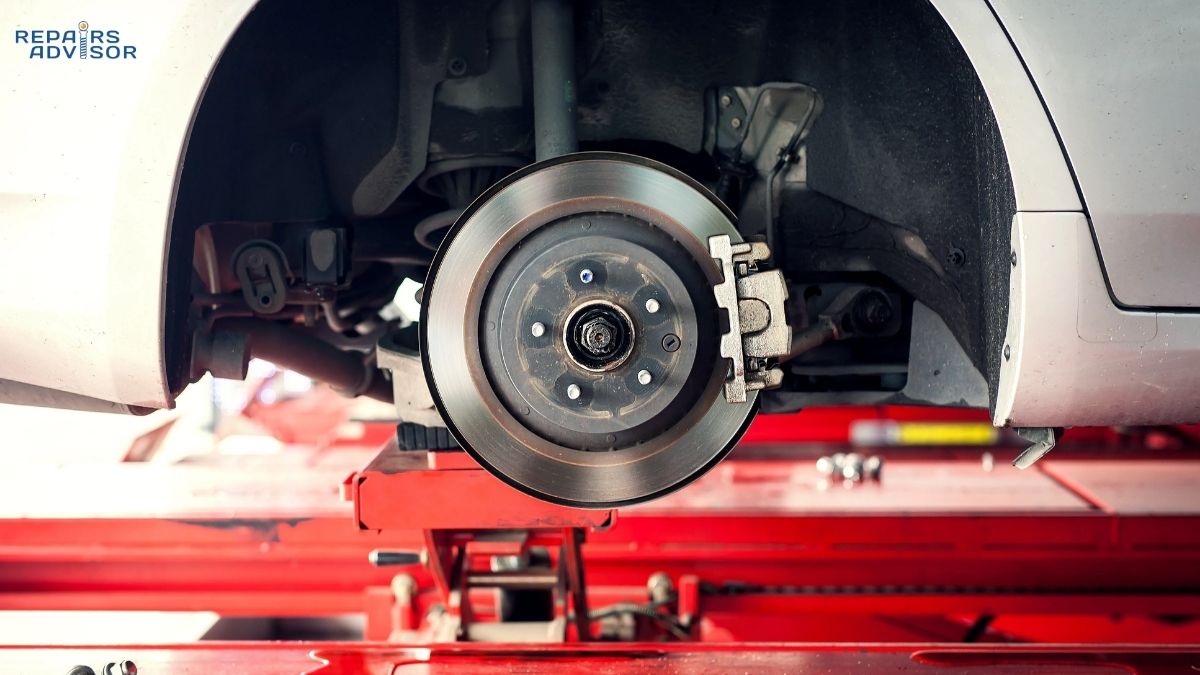
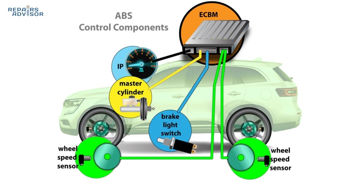
A wheel speed sensor is an electronic component mounted at each wheel — one per corner on modern vehicles — that measures that wheel’s rotational speed. The data it generates feeds the ABS control module, which uses it to prevent wheel lockup during hard braking. The same signal also drives traction control, electronic stability control, the speedometer, and on some platforms, the automatic transmission’s gear-change timing.
“ABS sensor” and “wheel speed sensor” mean the same thing. WSS is the correct designation in service literature, but both names are used interchangeably in shops and DIY communities. Because the sensor mounts at each wheel — exposed to road debris, water, heat, and constant vibration — it operates in one of the harshest environments of any electronic component on the vehicle.
How Wheel Speed Sensors Work: Two Types Explained
There are two fundamentally different wheel speed sensor designs. The distinction matters for diagnosis, because each type requires a different testing approach and fails in different ways.
Passive (Magnetic Reluctor) Sensors
Passive sensors are the older design, found on most vehicles built before the late 1990s and still used on some applications. The sensor is a permanent magnet with a fine copper wire wound around a metal core — essentially a miniature generator. It sits in close proximity to a toothed metal ring called the tone ring or reluctor ring, which rotates with the wheel. As each tooth passes the sensor tip, it disrupts the magnetic field and induces a small voltage in the coil. The result is an alternating current (AC) signal whose frequency rises with wheel speed.
This self-generating characteristic is what defines a passive sensor — it produces its own signal without external power. The working principle is directly analogous to how crankshaft position sensors operate: a reluctor wheel and magnetic pickup convert mechanical rotation into a frequency-based electrical signal. The ABS module monitors that frequency; when one wheel slows dramatically relative to the others, it triggers anti-lock intervention.
The main limitation is accuracy at very low speeds. Below roughly 3–5 mph, the AC signal becomes too weak for reliable interpretation, which can cause false ABS activation at the end of a stop. Passive sensors use a two-wire connector.
Active (Hall Effect / Magneto-Resistive) Sensors
Active sensors are standard on most vehicles from the late 1990s onward. They require an external power supply from the ABS control module to power their internal signal-conditioning circuitry. In return, they produce a clean digital square wave that toggles between two states as the tone ring passes: a low state (approximately 0.9V) and a high state (approximately 1.65V). The switching rate corresponds directly to wheel speed.
Active sensors read wheel speed accurately all the way to zero mph, which improves ABS control during the final moments of a stop. They can also detect wheel rotation direction — information that enables hill-hold and hill-descent functions. This accuracy is also why traction control systems on modern vehicles respond effectively even at low speeds during acceleration. Active sensors use two or three wires depending on the platform.
On many newer vehicles, the tone ring is integrated into the wheel bearing’s grease seal rather than sitting as a separate component on the axle. This sealed design provides good protection from contamination, but it means bearing failure typically compromises the sensing function at the same time.
Which Systems Depend on Wheel Speed Sensor Data?
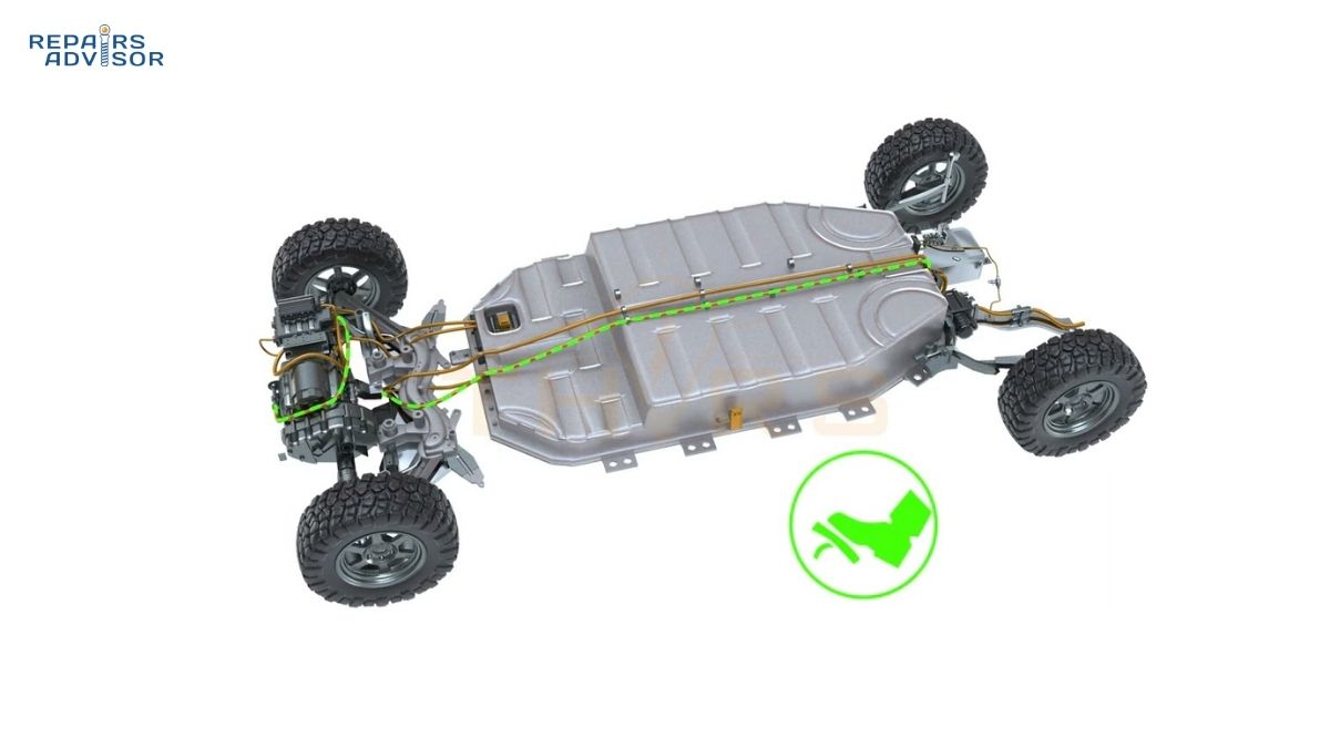
The wheel speed sensor signal is shared across multiple vehicle systems simultaneously. An invalid or absent signal from a single corner affects all of them.
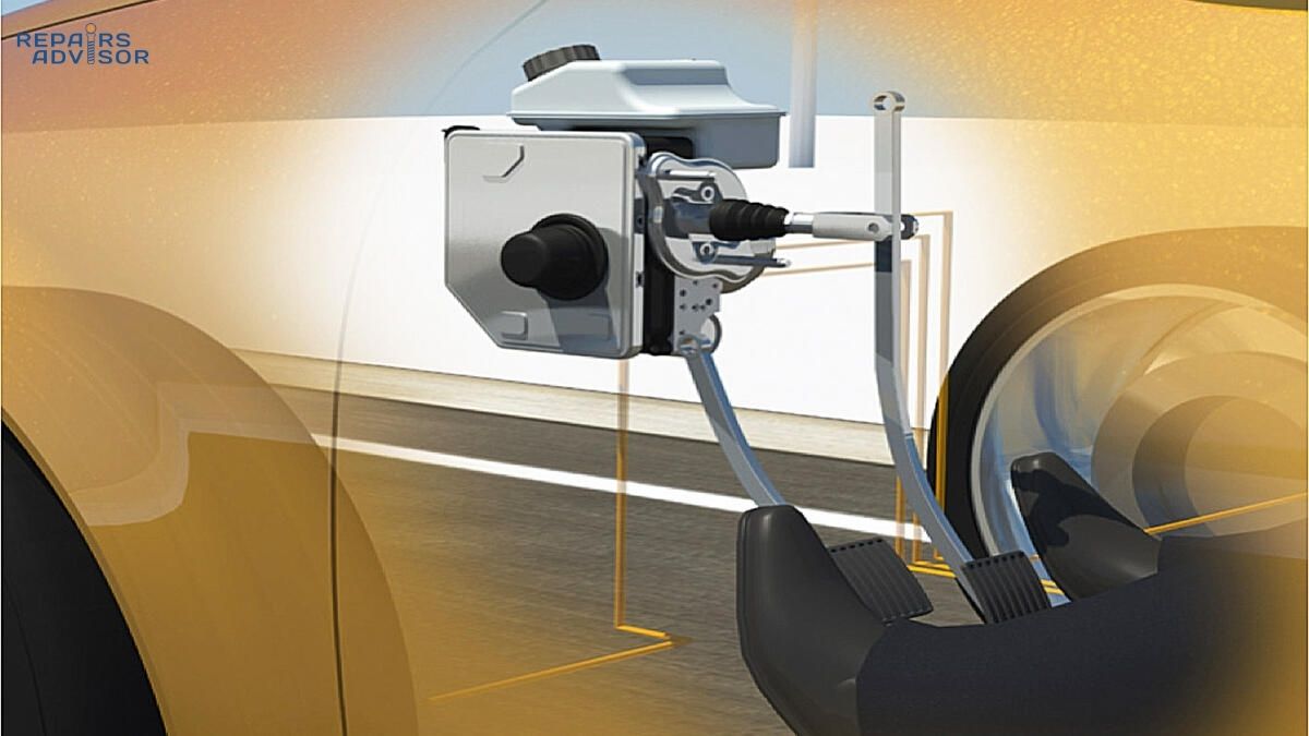
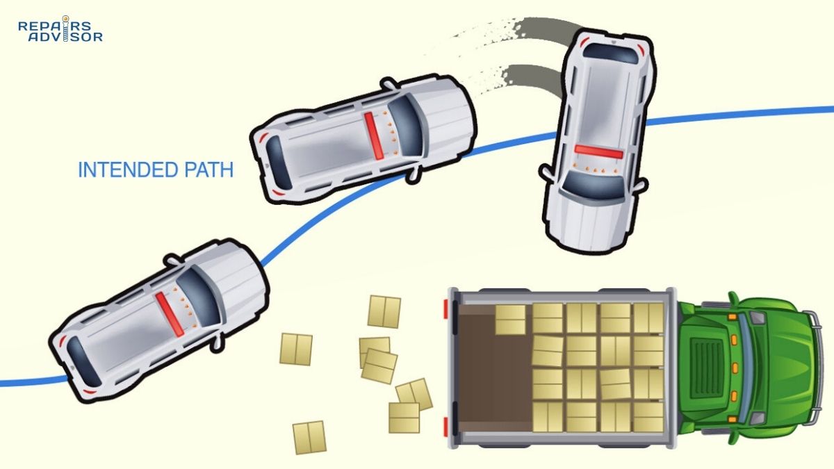
ABS is the primary consumer. The module compares the rotational speed of all four wheels in real time and releases brake pressure in rapid pulses to any wheel approaching lockup. Without reliable speed data, ABS disables itself entirely. Electronic stability control (ESC) pairs wheel speed data with inputs from the yaw rate sensor to detect oversteer and understeer, then selectively brakes individual wheels to bring the vehicle back in line. A faulty WSS corrupts that calculation.
Traction control compares driven wheel speeds against non-driven wheels. When a drive wheel spins faster than the others, the system reduces engine torque, applies the brake at that wheel, or both. The speedometer also draws vehicle speed from WSS signals on many vehicles — a failed sensor can cause the speedometer to read zero or fluctuate erratically at certain speeds.
Symptoms of a Bad Wheel Speed Sensor
Wheel speed sensor failure tends to produce a recognisable cluster of warning lights and specific driveability complaints.
Dashboard Warning Lights
The ABS warning light is typically the first to appear. When the ABS module detects an invalid or absent signal, it disables the system and illuminates the warning. As other systems that depend on the same data lose their input, the traction control and stability control warning lights usually follow. The check engine light may appear on some platforms as well.
A common diagnostic mistake is treating each warning light as a separate fault. When ABS, traction control, and stability lights come on together on a vehicle that was running normally, a single failed wheel speed sensor is a very likely explanation — not three independent system failures occurring simultaneously.
Driveability Symptoms
False ABS activation is a telling sign — the system pulsing the brakes during a normal low-speed stop, often in the final moments before the vehicle halts. This happens when a degraded passive sensor produces a weak or erratic signal that the module misreads as impending lockup. A worn tone ring with inconsistent tooth heights can produce the same symptom even if the sensor itself is undamaged.
Wheels locking up during hard braking is the opposite failure mode — ABS not functioning because it has no valid speed data. On wet or loose surfaces, this significantly increases stopping distances and removes steering control during emergency braking. Traction control activating without actual wheel slip, or failing to activate when wheels are genuinely spinning, are also consistent with WSS issues. Some vehicles display erratic speedometer readings when a sensor signal is corrupted.
Safety note: When both ABS and traction control are inactive, emergency braking and low-traction acceleration performance are meaningfully reduced compared to normal vehicle operation. Treat a confirmed WSS failure as a priority repair rather than a dashboard light to monitor over time.
Why Wheel Speed Sensors Fail
The sensor’s location — millimetres from the road surface at a rotating wheel — creates multiple failure pathways.
Contamination is the most common cause. Metallic debris from worn brake components is magnetically attracted to the sensor tip, building up a layer that interferes with signal generation. Brake dust, road grime, and packed mud contribute similarly. Thoroughly cleaning the sensor tip and tone ring face should always precede electrical testing — it resolves many apparent sensor faults without a replacement part.
Corrosion attacks the connector and wiring. Road salt and moisture infiltrate the connector over time, producing intermittent signals that come and go with temperature changes. This makes diagnosis harder, because the fault code may not be present on every scan. Applying dielectric grease to connectors during any brake service extends sensor life noticeably.
Physical damage from stone impacts, improper jacking near the sensor housing, or harness routing errors after suspension work can crack the sensor body or damage the internal electronics without visible external evidence. The wiring harness is vulnerable to chafing against suspension arms as they cycle through their travel range, progressively abrading insulation and eventually breaking conductors.
Tone ring damage is a separate failure that closely mimics sensor failure in its symptoms. A cracked, heavily corroded, or bent tone ring creates gaps in the pulse pattern that the sensor faithfully reports as erratic wheel speed. The sensor is working correctly — but what it is reading is wrong. Visual inspection of the ring before ordering a replacement sensor avoids unnecessary parts cost.
On vehicles with sealed hub-bearing assemblies, the tone ring is built into the bearing seal. When bearing wear creates excessive play, the air gap between sensor tip and ring widens, weakening the signal and eventually triggering fault codes. Replacing just the sensor on these platforms typically does not resolve the underlying issue — the complete hub assembly requires replacement. Understanding the wheel bearing relationship is important context for diagnosing hub-integrated sensor faults correctly.
Diagnosing a Faulty Wheel Speed Sensor
A systematic approach — codes first, visual second, electrical third — avoids the costly mistake of replacing a sensor that was not the root cause.
Step 1: Read Codes with an ABS-Capable Scan Tool
Wheel speed sensor faults are stored in the ABS module as chassis codes, not engine codes. A basic OBD-II reader that retrieves only P-codes will typically return nothing, even with the ABS light on. You need a scan tool capable of accessing ABS module data and reading C-codes.
Common codes point to specific corners: C0031 indicates the left front sensor circuit, C0035 the right front, C0045 the left rear, and C0050 the right rear. A confirmed code identifies which corner to focus on, but it confirms a circuit fault rather than a definitively failed sensor — the wiring, connector, and tone ring are equally valid starting points. For a grounding in how fault codes work more broadly, the OBD codes guide covers the diagnostic fundamentals.
After identifying the suspect corner, use the scan tool’s live data stream while driving slowly. A sensor showing zero mph while the others read 20 mph is almost certainly failed or disconnected. A sensor reading 18 mph against others at 20 mph suggests a dirty tone ring or a widened air gap — a distinction that often means cleaning rather than replacement.
Step 2: Visual Inspection
With the wheel removed, inspect the sensor body for cracks or impact marks. Trace the wiring harness to the connector, looking for chafed insulation, kinks, or areas of obvious heat damage. Check the connector for bent pins and corrosion. Inspect the tone ring directly — look for missing teeth, cracks, and heavy rust. Clean the sensor tip and the ring face with a non-abrasive cleaner and rag before proceeding to electrical testing.
Step 3: Electrical Testing
For passive sensors, a digital multimeter is sufficient. Disconnect the sensor from the harness and measure resistance across the two terminals. A healthy passive sensor reads 1,000–2,500 ohms. An open-circuit reading (OL or infinite) means a broken wire or failed coil. A reading near zero indicates a short. Either result means replacement. As a secondary check, set the meter to AC voltage and have an assistant spin the hub by hand — a working sensor should produce approximately 0.5–1.5V AC, increasing with hub speed.
For active sensors, resistance testing alone is unreliable and may damage internal circuitry. With the ignition on and the sensor connected to its harness, back-probe the connector to verify reference voltage from the ABS module — approximately 12V supply should be present. For signal verification, an oscilloscope displaying a clean square wave output is the most definitive test. A scan tool with graphing capability works as a practical alternative: watch for a waveform that changes frequency smoothly as the wheel turns. A flat line or erratic pattern while the wheel is spinning indicates sensor failure or a damaged tone ring.
Professional note: Graphing all four WSS signals simultaneously on a scope makes it immediately clear which sensor is producing an irregular signal. Diminished amplitude in a passive sensor’s sine wave — a flattened pattern rather than full-height peaks — typically points to an enlarged air gap from bearing wear rather than sensor failure, which changes the repair path entirely.
Wheel Speed Sensor Replacement
Replacement complexity depends significantly on whether the sensor is a standalone external unit or built into the hub bearing assembly.
Standalone External Sensor
On many vehicles, the sensor is a separate component bolted to the steering knuckle or hub carrier with a single bolt, with the harness clipped along the suspension to a connector behind the wheel arch liner. This configuration is accessible for intermediate DIYers.
The procedure: raise and support the vehicle on jack stands, remove the wheel, unclip and disconnect the wiring harness, remove the mounting bolt (typically 7–10 Nm), and pull the sensor from its bore. Clean the bore with a wire brush before installing the replacement — corrosion left in the bore affects the sensor’s position and air gap. Torque the mounting bolt to specification, re-clip the harness, reconnect the connector with a small amount of dielectric grease, then clear fault codes and verify with a test drive while monitoring live wheel speed data.
Hub-Integrated Sensor
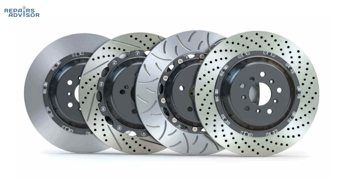
When the sensor is integrated into the wheel bearing seal, it cannot be replaced independently — the complete hub assembly must be replaced. On front-wheel-drive applications, this typically requires removing the brake caliper, the brake rotor, and the axle nut before the hub can come free. Checking the condition of the brake pads and rotors while the assembly is apart is worthwhile — the incremental effort is small against the disassembly you’ve already completed.
Axle nut torque is critical and frequently mishandled. The specification typically ranges from 150–300 ft-lbs depending on the vehicle. Using an impact wrench to run the nut down rather than a calibrated torque wrench risks overtightening, which crushes the bearing races and can cause the new hub to fail well before its expected service life. Always torque to the vehicle manufacturer’s specification. Given the variation in bearing press requirements, axle nut procedures, and access difficulty across platforms, having a vehicle-specific repair manual is strongly recommended before attempting hub bearing replacement for the first time.
When to Consult a Professional
Standalone sensor replacement is manageable for an intermediate DIYer comfortable with suspension and brake work. Several situations, however, call for professional involvement.
If fault codes return after replacing the sensor, the underlying issue may be a damaged tone ring that was missed during inspection, a wiring harness fault between the sensor and the ABS module, or in less common cases, an ABS module fault. Multiple WSS codes across different corners appearing simultaneously are more likely to indicate a module ground or power supply fault than coincidental sensor failures on multiple wheels.
Hub-integrated replacements on unfamiliar platforms, any situation involving a damaged tone ring that requires pressing or machining work, and cases where the initial diagnosis doesn’t clearly point to a single failed component are all situations where a qualified technician’s assessment is the more reliable path. Brake and suspension components are directly safety-critical — the cost of misdiagnosis is higher here than in most other systems.
Summary
Wheel speed sensors are small in size but significant in consequence. A single failed sensor can simultaneously disable ABS, traction control, and stability control — the systems most needed in emergency situations. The diagnosis path is logical: read chassis codes with an ABS-capable scan tool, inspect and clean visually before testing electrically, and match your testing method to the sensor type. Standalone replacements are achievable with methodical preparation; hub-integrated replacements require more care but are within reach with the right vehicle reference material. The C-code diagnostic section covers the broader range of chassis fault codes, including the complete family of wheel speed sensor circuit codes across all four corners.
Wheel Speed Sensor FAQ: Your Questions Answered
Whether you’ve just seen an ABS warning light or you’re trying to understand what a wheel speed sensor actually does, this FAQ covers the most common questions — from how the sensor works and what symptoms to watch for, to whether you can keep driving and what replacement realistically involves.
Quick Answer
A wheel speed sensor monitors how fast each wheel rotates and feeds that data to the ABS, traction control, and stability control systems. When one fails, those safety systems typically shut down and warning lights appear. Most standalone sensor replacements cost $50–$200 in parts and are achievable for intermediate DIYers; hub-integrated replacements involve more work and higher parts cost. Driving with a failed sensor is not recommended — ABS and traction control will be inactive until the fault is resolved.
What does a wheel speed sensor actually do?
A wheel speed sensor measures the rotational speed of its wheel and transmits that data to the vehicle’s ABS control module. There is one sensor per wheel on modern vehicles — four in total. The ABS module compares all four readings in real time; if one wheel starts decelerating significantly faster than the others during braking, the module reduces hydraulic pressure to that wheel to prevent lockup and maintain steering control.
The same signal feeds traction control, which uses it to detect spinning drive wheels and intervene with brake or throttle input. Electronic stability control combines wheel speed data with yaw rate and steering angle inputs to detect and correct oversteer or understeer. On many vehicles, the speedometer and the automatic transmission’s shift logic also draw from wheel speed sensor signals — which is why a failed sensor can sometimes affect the speedometer or cause transmission hesitation on certain platforms.
What are the symptoms of a bad wheel speed sensor?
The most common signs are:
- ABS warning light — typically the first dashboard indicator, appearing as soon as the module detects an invalid or absent signal
- Traction control and stability control warning lights — these usually follow once the shared sensor signal is lost
- False ABS activation — the system pulsing the brakes during a normal low-speed stop or at the very end of a stop cycle
- Wheels locking during hard braking — the opposite problem: ABS failing to activate when it should
- Erratic or dropped speedometer reading — on vehicles that derive vehicle speed from wheel sensor data
- Traction control activating without wheel spin — or failing to activate when wheels are genuinely spinning
A useful pattern: when ABS, traction control, and stability control lights all come on simultaneously on an otherwise normally running vehicle, a single failed wheel speed sensor is a likely common cause — not three independent system failures happening at once.
Is it safe to drive with a bad wheel speed sensor?
Your standard braking hydraulics remain operational — pressing the brake pedal will still slow the car. However, ABS and traction control are inactive, which meaningfully reduces your safety margin in emergency situations. Wheels can lock under hard braking, stopping distances increase on wet or loose surfaces, and vehicle control during emergency manoeuvres is reduced compared to normal operation.
The practical risk depends on your driving conditions. A short trip on dry roads in light traffic is different from a wet-weather highway commute. As a general rule, a failed wheel speed sensor should be diagnosed and repaired promptly rather than treated as a warning light to manage around. Understanding what the disc brake system can and cannot do without ABS assistance helps put the risk in perspective.
Can you clean a wheel speed sensor instead of replacing it?
Yes — and cleaning should always be the first step before any electrical testing or parts ordering. Metallic brake dust and road debris accumulate on the sensor tip and the face of the tone ring, which can interfere with the magnetic field enough to trigger fault codes and warning lights. Removing the sensor, cleaning the tip with a non-abrasive cleaner, and cleaning the tone ring surface resolves a meaningful proportion of apparent sensor failures without any replacement parts.
If cleaning clears the warning light but it returns within a few hundred kilometres, the sensor itself is likely degraded and should be replaced. Cleaning is a diagnostic step, not a long-term remedy for an electrically failed sensor — an open-circuit or short-circuit failure cannot be resolved by cleaning.
How do you diagnose which wheel speed sensor has failed?
The most reliable starting point is an OBD-II scan tool capable of accessing ABS module data. Standard chassis codes (C-codes) identify the specific corner: C0031 is typically the left front, C0035 the right front, C0045 the left rear, and C0050 the right rear — though exact code-to-corner mapping varies by manufacturer. A basic engine-only code reader frequently returns nothing even with the ABS light on, because the fault is stored in the ABS module, not the engine ECU.
Once the corner is identified, use the scan tool’s live data stream while driving slowly. A sensor reading zero while the others show vehicle speed is almost certainly failed or disconnected. A sensor reading slightly lower than the others suggests a dirty tone ring or an air gap issue rather than a dead sensor — an important distinction that often means cleaning rather than replacement.
For passive sensors, a multimeter resistance check provides a quick go/no-go result: disconnect the sensor and measure across its two terminals. A healthy reading is 1,000–2,500 ohms; open circuit or near-zero means replacement is needed. For active sensors on newer vehicles, resistance testing is unreliable — use live data monitoring or check for reference voltage at the connector with the ignition on. The C0031 code article walks through the full diagnosis sequence for a left-front sensor fault; the same logic applies to all four corners.
What causes wheel speed sensors to fail?
Several factors contribute, often in combination:
- Contamination — metallic debris from worn brake pads and rotors builds up on the sensor tip, weakening signal strength
- Corrosion — road salt and moisture infiltrate the connector, causing intermittent or lost signal, often worse in cold weather when metal contracts around degraded contacts
- Physical damage — stone impacts, improper jacking near the sensor housing, or harness routing errors after suspension or brake work
- Wiring damage — harness chafing against suspension components through their travel range, or heat damage near exhaust routing
- Tone ring damage — a cracked, corroded, or bent tone ring produces erratic signals that closely mimic sensor failure; the ring must be inspected before condemning the sensor
- Bearing wear — on vehicles with hub-integrated sensors, bearing wear widens the sensor’s air gap and degrades signal quality; the wheel bearing and sensor effectively fail together on these platforms
How long do wheel speed sensors last?
Sensors are designed to last the life of the vehicle, but real-world service life varies considerably. Parts suppliers commonly cite 60,000–150,000 miles under normal conditions, with earlier failure on vehicles operated in heavy road-salt environments, coastal regions, or conditions with high brake dust accumulation.
Most sensor failures are externally triggered — contamination, corrosion, and physical damage — rather than internal wear-out. A vehicle in a wet, salty climate may see sensor issues significantly earlier than the theoretical lifespan, while a lightly used vehicle in a dry region may never need a sensor replaced at all.
Can you replace a wheel speed sensor yourself?
For standalone external sensors — mounted to the steering knuckle with a single bolt, harness clipping separately along the suspension — this is a reasonable job for an intermediate DIYer with basic tools. The procedure: raise and support the vehicle on jack stands, remove the wheel, unplug the harness, remove the mounting bolt (typically 7–10 Nm), pull the sensor, clean the mounting bore, and install the replacement. Apply dielectric grease to the connector before plugging in, then clear fault codes and verify with a test drive monitoring live wheel speed data.
For hub-integrated sensors built into the wheel bearing assembly, the sensor cannot be replaced independently — the complete hub bearing must come out. This involves removing the brake caliper, rotor, and axle nut. The axle nut torque specification is critical: it typically runs 150–300 ft-lbs, and using an impact wrench instead of a calibrated torque wrench risks overtightening and premature bearing failure. This repair is achievable for experienced DIYers with a vehicle-specific repair manual; first-timers are advised to review the full procedure for their specific platform before starting.
Safety note: All wheel removal work should be performed with the vehicle properly supported on jack stands. If you’re uncertain about any step of the procedure for your specific vehicle, a qualified technician’s input is worthwhile — brake and suspension components are directly safety-critical.
How much does wheel speed sensor replacement cost?
Standalone external sensor parts typically run $30–$200 depending on the vehicle. Common domestic sedans and most Japanese platforms are at the lower end; European imports and some truck/SUV applications are at the higher end. Hub-integrated replacements cost more because the complete bearing assembly is replaced — typically $150–$400 for the hub unit, more on some platforms.
Professional labour adds $80–$150 per hour in most markets. Shops typically estimate 1–2 hours for a standalone sensor including diagnostic time, and 2–3 hours for hub-integrated work. Total professional cost for a standalone sensor on a common vehicle is often $150–$400; hub-integrated jobs can reach $400–$700 or more. DIY saves the labour component, which frequently equals or exceeds the parts cost.
Should you replace sensors in pairs or all four at once?
No — wheel speed sensors should be replaced only as needed based on diagnosis. Unlike brake pads, where replacing across the axle maintains balanced performance, each wheel speed sensor operates independently and replacing additional sensors that are passing their tests adds unnecessary cost with no benefit. If a fault code points to one corner, replace that sensor and verify the repair before considering anything else.
OEM or aftermarket: which should you choose?
For most common domestic and Japanese platforms, quality aftermarket sensors from reputable brands perform reliably and cost significantly less than OEM. The key qualifier is part quality: very cheap sensors with no brand recognition have a documented history of premature failure or intermittent faults that create more diagnostic work than they save in upfront cost.
For European vehicles, and platforms with advanced driver assistance systems that require tighter signal tolerances, OEM or OEM-equivalent parts (Bosch, Continental, Hella for European marques) are the safer choice. When uncertain, match the specification to the original — a repeat repair costs more than the initial price difference. For a deeper look at how the sensors themselves work, the differences between passive and active types, and the full diagnostic and replacement process, the wheel speed sensor guide covers all of it in detail.