Disc brakes are fitted to roughly 90 percent of modern passenger vehicles, yet most drivers couldn’t explain how they actually work. That gap matters — because understanding your disc brake system helps you recognise problems early, make informed maintenance decisions, and know when a job is within your skill level versus when it belongs in a professional workshop. A healthy disc brake caliper generates between 800 and 2,000 pounds of clamping force every time you press the pedal. Understanding where that force comes from, how it’s controlled, and what it does to the rotor and pad is the foundation of every brake-related decision you’ll ever make.
This guide covers the full picture: the core components and how they’re built, the physics behind hydraulic braking, caliper and rotor types, brake pad compounds, the difference between disc and drum setups, brake fade, electronic integration, and how to read the warning signs before something goes wrong.
How Do Disc Brakes Work?
Disc brakes work by using hydraulic pressure from the master cylinder to push brake pads against a spinning rotor (disc). When you press the brake pedal, fluid pressure extends one or more pistons inside the caliper, clamping the pads against both faces of the rotor. The friction between pad and rotor converts the vehicle’s kinetic energy into heat, slowing the wheel. When you release the pedal, pressure drops, piston seals retract the pistons a fraction of a millimetre, and the pads clear the rotor surface ready for the next application.
Disc Brake Components: What Each Part Does
A disc brake system is simpler than it looks. Strip away the wheel and you’re working with four core elements that work as a system: the rotor, the caliper, the brake pads, and the hydraulic circuit that connects your foot to all of it. Understanding how the master cylinder and brake booster work together to generate that hydraulic pressure is worth reading alongside this guide, because the caliper is really just the endpoint of a force-multiplication chain that starts at your foot.
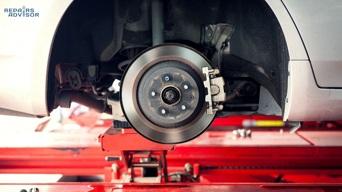
The Brake Rotor
The rotor is the flat, circular disc bolted to the wheel hub that spins with the wheel. Most OEM rotors are cast from grey iron or high-carbon iron, chosen for their combination of thermal mass, wear resistance, and predictable friction characteristics. Front rotors on passenger cars typically measure 280–330mm in diameter and 20–28mm thick; rear rotors are smaller — often 258–280mm across and 8–14mm thick — because the rear axle carries a lower share of the braking load during deceleration.
The rotor’s job is twofold: it provides the friction surface that the pads clamp against, and it acts as the primary heat sink for the energy generated during braking. A full emergency stop from highway speed can push rotor surface temperatures above 700°C in a matter of seconds. The rotor’s material, design, and condition all directly affect how well it manages that thermal load.
The Brake Caliper
The caliper is the clamping mechanism. It straddles the rotor and houses one or more hydraulic pistons that push the brake pads against the rotor faces when pressure is applied. Calipers come in two fundamental designs — floating (sliding) and fixed — which are covered in detail in the section below. What they share is the same basic mechanism: hydraulic fluid pressure acting on a piston to convert fluid force into mechanical clamping force.
Inside every caliper are square-section rubber piston seals that do something important beyond just preventing leaks. When hydraulic pressure pushes the piston outward, those seals flex and distort slightly. When pressure is released, they spring back — pulling the piston 0.1–0.25mm away from the pad. This tiny retraction clearance is what prevents constant pad drag on the rotor, which would cause heat buildup, premature wear, and reduced fuel economy.
Brake Pads
Brake pads are steel backing plates with friction material bonded or riveted to the face that contacts the rotor. The friction material compound varies significantly by manufacturer and intended use — ranging from soft organic compounds rated to around 400°F before fade onset, up to semi-metallic and ceramic formulations that can tolerate temperatures above 700°F. For a deeper look at how brake pads and rotors interact across their service life, including transfer layer behaviour and wear patterns, that article goes into the surface chemistry in detail.
Most road-going brake pads also have a wear indicator — a small metal tab attached to the backing plate. When the friction material wears down to roughly 2–3mm, the tab contacts the rotor and produces the characteristic high-pitched squeal that signals it’s time to inspect the brakes.
Supporting Components
Completing the caliper assembly are rubber dust boots that protect the piston faces and caliper bores from road contamination, bleeder valves that allow air to be purged from the system during fluid service, and on floating calipers, the guide pins or slide bolts that allow the caliper body to move laterally as the pads wear. Those guide pins require periodic lubrication with high-temperature brake grease — seized guide pins are among the most common causes of uneven pad wear and brake pull.
How Disc Brakes Work: The Physics of Stopping
The sequence from pedal press to stopped wheel takes a fraction of a second and involves some elegant physics. Here’s what’s actually happening.
Step-by-Step: Pedal to Rotor
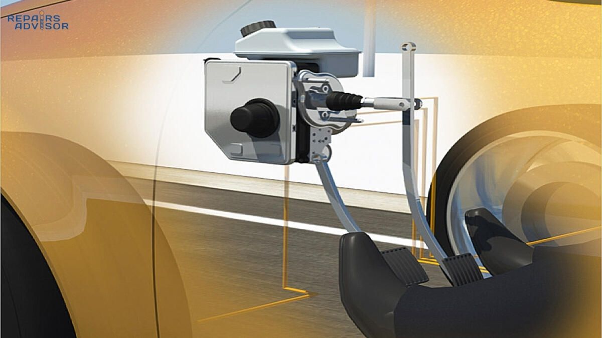
When you press the brake pedal, it pushes a rod into the master cylinder — a hydraulic pump that converts your pedal force into fluid pressure. On most vehicles, a vacuum brake booster sits between the pedal and master cylinder, using engine vacuum to amplify your leg force by a factor of 3–4×. That means a 50–100 lbf push at the pedal becomes 250–400 lbf at the master cylinder piston before hydraulic pressure is even calculated. Understanding how brake fluid transmits this hydraulic force through the system without compressing — which is why incompressible fluid is non-negotiable — explains why even small air bubbles produce a spongy pedal.
The pressurised fluid travels through steel brake lines and flexible rubber hoses to each wheel’s caliper. In a floating caliper, the fluid enters behind the single inboard piston and pushes it outward. The inboard pad contacts the rotor first. As pressure builds, the caliper body reacts — it slides inward on its guide pins, dragging the outboard pad into contact with the opposite rotor face. The result is both pads gripping the rotor simultaneously from either side.
In a fixed caliper, opposing pistons on both sides receive pressure at the same time and clamp both pads against the rotor with equal force — no caliper body movement required.
Pascal’s Law and Hydraulic Advantage
The reason disc brakes can generate so much clamping force from modest pedal effort comes down to Pascal’s Law: pressure applied to an enclosed fluid transmits equally in all directions. The master cylinder piston is small — typically 22–25mm in diameter. The caliper piston or pistons are considerably larger in total area. Because pressure is force divided by area, the same pressure acting on a larger area produces more force. A system running 1,000 psi of line pressure acting on a pair of 40mm caliper pistons produces well over 2,000 lbf of clamping force at that wheel. That’s the hydraulic advantage that makes disc brakes both effective and controllable.
One important calibration point: front brakes handle approximately 60–70% of total braking effort. During deceleration, vehicle weight transfers forward, loading the front tyres more heavily and increasing the work the front brakes must do. This is why front rotors are larger, front pads are thicker, and front calipers often have more pistons than their rear counterparts. How the brake booster amplifies pedal input is worth understanding if you’re working on or diagnosing the hydraulic side of the system.
Caliper Types: Floating vs Fixed
The type of caliper fitted to your vehicle affects braking feel, maintenance requirements, and the kind of wear patterns you’ll encounter.
Floating (Sliding) Calipers
The floating caliper is the standard fitment on the vast majority of passenger vehicles, from economy hatchbacks to everyday SUVs. It uses a single piston — sometimes two — on the inboard side of the rotor. When hydraulic pressure pushes the piston outward, the caliper body reacts by sliding inward on two guide pins, pulling the outboard pad into contact. The whole assembly floats; hence the name.
The advantages are cost, weight, and packaging. Floating calipers are lighter and more compact than fixed designs, and they’re significantly cheaper to manufacture and replace. The weakness is the guide pins. If they corrode, seize, or run dry of grease, the caliper stops sliding freely. One pad then contacts the rotor more than the other, producing uneven wear — sometimes dramatically so. You might find the inboard pad worn to the metal while the outboard pad has 8mm of material remaining. Seized guide pins also cause a constant low-level drag, which builds heat and accelerates rotor wear.
Fixed Calipers
Fixed calipers are bolted rigidly to the hub carrier and don’t move. Instead, they carry pistons on both sides of the rotor — typically two, four, or six pistons in opposing pairs. When hydraulic pressure is applied, all pistons move simultaneously, pressing both pads against the rotor with equal force from each side.
The performance advantages are real: more even pressure distribution across the pad face, better thermal management due to greater caliper mass, and superior pedal feel — the feedback through the pedal is sharper and more progressive. Four-piston fixed calipers from Brembo, Bosch, or TRW are found on most performance variants and hot hatches; six-piston monobloc calipers appear on sports cars and high-performance trucks. The trade-off is cost, weight, and — in corrosive climates — vulnerability to corrosion between the piston bores and the caliper bridge.
Safety note: Caliper replacement on either type requires correct torque of mounting hardware, proper piston retraction, and a full brake bleed to remove any air introduced during the job. If you haven’t bled a brake system before, this is a good procedure to learn with a second person present. Anyone unfamiliar with hydraulic brake system service should have the work inspected by a qualified technician before driving.
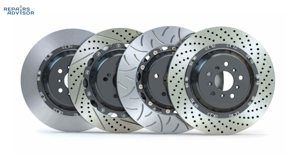
Rotor Types: Solid, Vented, Drilled, and Slotted
Not all rotors are equal. The design of the friction faces and the internal construction of the rotor have a significant impact on heat dissipation, wear characteristics, and suitability for different driving conditions.
Solid Rotors
A solid rotor is exactly that — a single-piece disc with no internal structure. They’re the lightest option and adequate for rear axles on non-performance vehicles, where the braking load is lower. The rear brakes on most passenger cars handle only 30–40% of total braking effort, so a solid rotor with less thermal capacity is entirely appropriate there.
Vented Rotors
Vented rotors consist of two parallel friction rings connected by a series of internal vanes or straight pillars. The channel between the faces acts as an air passage — as the rotor spins, it draws air inward from the centre and expels it at the outer edge, continuously cooling the friction surfaces. The improvement in heat dissipation over a solid rotor is substantial, which is why virtually every front rotor on a modern passenger car is vented. Given that the fronts carry the majority of braking load, the extra cooling capacity is essential.
One critical note: vented rotors are thicker than solid rotors for the same vehicle position. They’re not interchangeable. If your vehicle’s front axle specifies vented rotors, fitting solid ones won’t work dimensionally and will severely compromise thermal performance.
Drilled Rotors
Cross-drilled rotors have holes bored through both friction faces. The benefits are real but limited: the holes reduce rotor mass, allow heat gases from pad outgassing to escape rather than forming a lubricating layer between pad and rotor, and provide a modest improvement in wet-weather braking by giving water a path off the friction surface. Where drilled rotors struggle is under sustained heavy use. The holes create stress concentration points, and aggressive track or repeated heavy-braking use can initiate cracks that propagate from the hole edges. For road use, occasional spirited driving, and canyon work, drilled rotors are a legitimate upgrade over plain vented units. For track use, the structural trade-off matters more.
Slotted Rotors
Slotted rotors have shallow channels machined into the friction surface — typically 2–3mm deep and set at a slight angle. They don’t penetrate the full thickness of the rotor, so they don’t compromise structural integrity the way drilling does. The slots serve a similar function: channelling gas, dust, and water away from the pad contact patch and continuously abrading the pad surface to keep it fresh and free of glaze.
The trade-off is pad wear. The slot edges create additional abrading action, so pads may wear faster against a slotted rotor than against a plain or drilled surface. For applications involving sustained high thermal loads — towing, repeated mountain descents, regular track use — slotted rotors are generally the more durable performance choice over drilled alone. Understanding how the friction and tribology of pads and rotors actually work together makes the rotor selection decision much clearer.
Drilled and Slotted
The combination design — drilled holes plus surface slots — is the most popular aftermarket upgrade. Brands like Brembo, PowerStop, and EBC all offer drilled-and-slotted options across a wide range of fitments. For enthusiast drivers who want meaningful thermal performance over stock without the structural concerns of pure drill patterns, a quality drilled-and-slotted rotor with chamfered (bevelled) hole edges is a solid choice.
Brake Pad Compounds: Choosing the Right Material
The friction material in a brake pad is not a commodity. The compound determines temperature tolerance, noise levels, rotor wear, dust output, and how the brakes feel under progressive or emergency application. Three compound families cover the vast majority of road vehicles.
Organic (NAO) Pads
Non-Asbestos Organic pads are the standard factory fitment on most new passenger vehicles. The friction material is a blend of Kevlar fibres, rubber, carbon compounds, and glass fibre, bound together with resin. They’re soft, quiet, produce minimal dust, and are gentle on rotor surfaces. They’re also the cheapest option and perform acceptably in everyday driving conditions.
The limitation is temperature. Organic compounds begin to degrade and outgas at around 400°F — a threshold that’s easy to reach during repeated hard stops, aggressive mountain driving, or towing. When the resin binds break down under heat, friction performance drops sharply. Organic pads are the right choice for light daily use; they’re the wrong choice for drivers who regularly push their brakes hard.
Semi-Metallic Pads
Semi-metallic pads contain 30–65% metal content by weight — steel wool, iron powder, copper alloys — bound with graphite lubricant and organic filler material. The metal content gives them significantly better heat tolerance than organics, excellent cold-temperature bite, and longer service life under demanding conditions. They’re the go-to compound for trucks, tow vehicles, performance street cars, and any application where the brakes see sustained heat loading.
The trade-offs are noise and rotor wear. Semi-metallic pads are harder than organics and more abrasive on rotor surfaces. They can also be grabby at cold temperatures — the first few brake applications on a cold morning may feel more aggressive than expected. If noise is a concern and driving style is moderate, semi-metallic may be more pad than the application needs.
Ceramic Pads
Ceramic compounds use dense ceramic material reinforced with copper fibres — though copper content has been progressively reduced since EPA regulations came into effect post-2015. Ceramic pads hit a useful middle ground: quieter than semi-metallic, more heat-tolerant than organic, and they produce fine dust that’s lighter in colour and less visible on alloy wheels. They offer consistent feel across a wide temperature range, which makes them popular on premium road cars.
Their limitations are cost and extreme-condition performance. Ceramic pads transfer more heat into the caliper and brake fluid than semi-metallic, which can accelerate fluid degradation in high-use scenarios. For full track use or very cold climates, semi-metallic compounds generally outperform ceramic at the thermal extremes. For the majority of road drivers, ceramic represents the best combination of performance, noise, and longevity.
Disc Brakes vs Drum Brakes
Many vehicles still use drum brakes on the rear axle — particularly economy cars and light commercial vehicles where cost outweighs the need for maximum rear braking performance. Understanding the comparison helps explain why disc brakes dominate modern vehicle design. How drum brakes work and why they remain in use on rear axles covers the self-energising geometry that makes drums effective at low cost.
The core differences: disc brakes dissipate heat far more effectively because the rotor is open to airflow and the pads make contact on the exposed outer faces. Drum brakes trap heat inside the drum, making them significantly more prone to fade under sustained use. In wet conditions, disc rotors shed water quickly — within the first brake application, the pad wipes the surface clear. Drum brakes can trap moisture inside the drum housing, causing temporary performance degradation until heat evaporates it. Disc pads are also far simpler to inspect visually; drum shoes require wheel removal and drum disassembly.
Where drums retain an advantage: cost (both manufacturing and replacement), and in some configurations, parking brake integration. Drums are easier to configure as a combined service-and-parking brake, which is why even some vehicles with rear disc brakes use a small integrated drum mechanism inside the rear rotor hat for the handbrake function.
Brake Fade: What It Is and How to Prevent It
Brake fade is a temporary loss of braking effectiveness caused by heat exceeding the system’s ability to dissipate it. Understanding the three forms helps you identify cause and take appropriate action.
Pad (Friction) Fade
The most common form. Organic pad compounds begin to break down above around 400°F; as the resin binders outgas under heat, a thin vapour layer forms between the pad and rotor surface. The friction coefficient drops, the pedal feels normal, but stopping distance increases dramatically. The effect is temporary — if you allow the brakes to cool, they’ll recover. The lesson is compound selection: drivers who regularly place high thermal demands on their brakes need a pad rated for those temperatures.
Fluid Fade
Brake fluid absorbs moisture from the atmosphere over time — a process called hygroscopic absorption. As the water content rises, the fluid’s boiling point drops. Fresh DOT 4 fluid has a dry boiling point of 230°C; after a year of service, that wet boiling point may be as low as 155°C. Under sustained heavy braking, if the fluid at the caliper reaches boiling point, it vaporises. Steam is compressible; hydraulic fluid is not. The result is a spongy, unresponsive pedal — sometimes called vapour lock. This is why brake fluid service intervals matter: replacing fluid every two years (or per the manufacturer’s schedule) maintains adequate boiling point margin.
Green Fade
New brake pads contain uncured resins that haven’t been exposed to heat yet. If you put significant braking demand on brand-new pads before they’re properly bedded in, those resins outgas and cause a temporary performance reduction. The fix is a proper bed-in procedure: five to eight moderate brake applications from 40 mph down to 10 mph, with intervals between each to allow cooling. This cures the surface resins and creates the transfer film on the rotor that optimises friction performance.
Prevention
On long descents, use engine braking instead of holding the brakes continuously. In an automatic, use manual mode or sport mode to hold a lower gear; in a manual, downshift and let the drivetrain do the work. This keeps the brakes cool by using them in short, firm applications rather than long, light ones. Select the right pad compound for your actual driving style. And change brake fluid on schedule. How ABS systems interact with a fading brake system is also worth understanding — ABS can mask some loss of hydraulic response while still cycling the calipers, meaning a driver might not notice fluid fade until it’s well advanced.
ABS and Electronic System Integration
Modern disc brakes don’t operate in isolation. They’re the physical actuators for a stack of electronic safety systems that depend on being able to modulate caliper pressure precisely and rapidly.
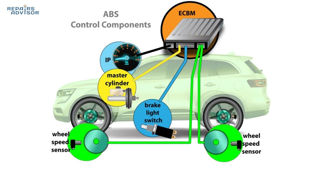
How ABS Works With Disc Brakes
The Anti-lock Braking System monitors each wheel’s speed 20–30 times per second via wheel speed sensors mounted at each hub. When the ECU detects a wheel decelerating faster than the others — indicating imminent lock-up — it commands the ABS hydraulic pump to modulate pressure to that caliper at 10–15 cycles per second: release, reapply, release, reapply. This keeps the wheel rotating, which maintains tyre-to-road traction and preserves steering input.
The important nuance: ABS does not always shorten stopping distance. On dry tarmac, a skilled driver with threshold braking technique can match or beat ABS stopping distances. What ABS provides is steering control during emergency braking — the ability to swerve around an obstacle while the brakes are fully applied. The rapid pedal pulsation you feel during ABS activation is normal and expected; the correct response is to maintain firm pedal pressure and steer.
ESC, Traction Control, and AEB
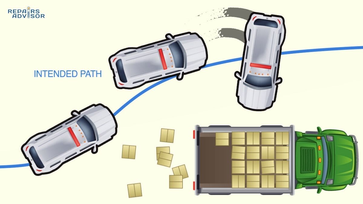
ABS is only the entry point. The same caliper-pressure modulation infrastructure enables a broader set of electronic interventions. Electronic Stability Control goes further — it uses individual caliper intervention on specific wheels to correct understeer and oversteer in real time, using yaw rate and lateral acceleration data to identify when the vehicle’s actual path diverges from the driver’s intended path. Traction Control applies selective brake pressure during acceleration to prevent driven wheels from spinning. Automatic Emergency Braking commands maximum hydraulic pressure autonomously when sensors detect an unavoidable collision.
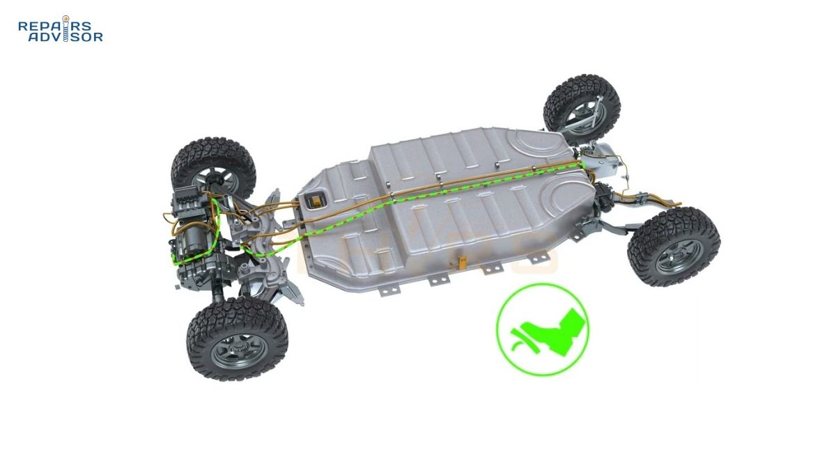
On hybrid and electric vehicles, the picture is more complex. Regenerative braking blends electric motor resistance with friction braking in a way that’s transparent to the driver — the brake pedal controls a blended response, and the system allocates energy recovery vs pad-and-rotor friction based on deceleration demand, battery state, and wheel speed conditions.
Disc Brake Wear Symptoms and Maintenance
Disc brakes give reasonably clear warning signs before they reach a dangerous state. Knowing what to listen and feel for means you can act before a minor service becomes a major repair.
Warning Signs to Act On
A high-pitched squeal during normal braking is usually the wear indicator tab touching the rotor — the built-in warning that pads are approaching minimum thickness (around 2–3mm of friction material remaining). This is an advisory; you have some time, but book an inspection promptly.
A grinding or growling noise during braking means the friction material has worn through and the steel backing plate is contacting the rotor. This is an urgent situation. Continued driving will score the rotor surface rapidly, turning what would have been a pad-only replacement into a full pad-and-rotor job. More importantly, metal-on-metal contact is a meaningful reduction in braking effectiveness.
A soft or spongy pedal that requires more travel than usual — especially if it has changed from a previous feel — indicates either air in the hydraulic circuit, a developing fluid leak at a caliper, hose, or line, or brake fluid at or near boiling point. Any of these warrants immediate diagnosis.
Steering wheel vibration or a pulsating pedal during braking usually points to rotor runout — the rotor is slightly warped or has developed uneven thickness variation from thermal cycling. The rotor surface isn’t perfectly flat, so the pad contact alternates between high and low spots as the rotor turns, creating that characteristic pulse through the chassis.
Vehicle pulling left or right during braking suggests uneven braking force — a common cause is a seized floating caliper guide pin on one side, holding a pad partially engaged or preventing it from engaging fully.
Rotor Inspection and Service Life
Every rotor has a minimum thickness specification, usually stamped on the rotor hat or listed in the vehicle service manual. Operating a rotor below minimum thickness is unsafe — the reduced thermal mass increases fade susceptibility, and the thinner section is more vulnerable to cracking under thermal stress. When measuring rotor thickness, take multiple readings around the circumference; uneven wear often shows up as thickness variation rather than uniform thinning.
Check for deep circumferential grooves (scoring), which reduce pad contact area and accelerate wear. Blue or purple discolouration indicates the rotor surface has been exposed to temperatures high enough to alter the crystalline structure of the iron — a sign of either a seized caliper or sustained overuse. Excessive lateral runout — the rotor wobbling side to side as it spins — should be below 0.05mm (0.002″) for most applications.
Typical rotor service life on a passenger car is 50,000–70,000 km under normal driving conditions, usually through two or three sets of brake pads. Aggressive driving, towing, or mountain driving will shorten that significantly.
DIY vs Professional Service Thresholds
Visual pad inspection through the wheel — checking that visible pad material remains above the steel wear indicator slot — is accessible to any vehicle owner with a torch. Measuring pad thickness with vernier calipers and inspecting for rotor scoring are well within the capability of an intermediate DIY mechanic.
Pad and rotor replacement is a popular DIY job with the right tools: a jack and stands, wheel brace, socket set, caliper wind-back or piston press tool, brake piston lubricant, and a basic brake bleeding setup. The job is achievable, but it requires systematic attention to torque specs (especially caliper mounting bolts — these are typically specified to 30–120 Nm depending on vehicle) and a proper bleed before driving.
Professional service is strongly recommended for: caliper rebuild or replacement when a piston is seized or a bore is corroded; any diagnosis involving spongy pedal or fluid leaks; ABS, ESC, or brake-by-wire fault codes; and brake fluid flush where the hydraulic circuit needs to be fully purged.
Safety reminder: Brakes are a safety-critical system. Incorrect reassembly — whether missing a spring clip, cross-threading a bleed nipple, or failing to properly seat a banjo bolt — can result in brake failure with zero warning. If there is any doubt about the quality of a DIY brake repair, have it inspected by a qualified technician before the vehicle goes on public roads. Your repair manual will have the torque specifications, minimum rotor thickness, and bleeding sequence specific to your vehicle — don’t guess at safety-critical figures.
Disc Brakes Across Vehicle Types
The principles of disc braking are consistent, but the hardware varies considerably by application.
On motorcycles, disc brakes are mounted via axial bolts (parallel to the wheel axle) on most standard bikes, or radial bolts (perpendicular to the axle) on performance machines — radial mounting is stiffer and delivers better pedal feel under hard braking. Wave or petal-shaped rotors are common; the irregular edge reduces weight and provides more cooling surface area than a plain disc. Single-piston floating calipers are standard on most street bikes; four and six-piston radial fixed calipers appear on sportbikes and premium motorcycles.
On trucks, SUVs, and tow vehicles, front rotor diameters typically run 330–380mm or larger, with greater rotor thickness to handle the higher thermal demands of heavier vehicles and towing loads. Rear disc brakes have become standard equipment on most full-size pickups and larger SUVs, replacing the rear drum setups that were common into the 2000s.
On performance and electric vehicles, carbon-ceramic rotors — used by Porsche (PCCB), Ferrari, and McLaren — offer extreme heat resistance and weight reduction at significant cost. EVs and hybrids present a unique braking environment: friction brakes work alongside regenerative systems, meaning pad and rotor wear is often substantially lower than on equivalent combustion vehicles. However, the reduced use of friction braking means rotors can develop surface corrosion more quickly between applications, which is worth factoring into maintenance planning.
For vehicle-specific brake specifications — rotor minimum thickness, caliper torque figures, pad part numbers, and bleeding procedures — a repair manual for your exact make and model is the definitive reference. Toyota repair manuals, Ford repair manuals, and BMW repair manuals cover the full brake system specifications for those platforms.
Putting It Together
Disc brakes work through three things in concert: hydraulic pressure amplified through Pascal’s Law, friction converting kinetic energy into heat, and rotor geometry designed to dissipate that heat fast enough to keep performance consistent. Understanding the relationship between the caliper, rotor, and pad — and how compound choice, rotor design, and maintenance interact — gives you the foundation to make informed decisions about every brake job, upgrade, or diagnostic scenario you’ll encounter.
The deeper layers of the system — how master cylinders manage the dual hydraulic circuits that provide front-rear redundancy, and how brake proportioning valves balance front and rear braking force as vehicle load changes — are worth understanding if you’re working through a diagnosis or planning a brake system upgrade. The brakes are only as good as the entire hydraulic chain, from pedal to pad.
FAQs
Disc brakes generate more questions than most vehicle systems — how the hydraulics work, when pads and rotors need replacing, what different rotor designs actually do, and which brake pad compound suits which driving style. These are the questions worth knowing the answers to, grouped so you can find what’s relevant quickly.
Disc Brakes: Quick Reference
Disc brakes use hydraulic pressure to squeeze brake pads against a spinning rotor, converting kinetic energy into heat to slow the vehicle. Key maintenance intervals: inspect pads every 20,000–25,000 km, replace when friction material drops below 3mm, and replace rotors when they reach the stamped minimum thickness or show deep scoring, heat discolouration, or excessive runout. Change brake fluid every two years to maintain hydraulic performance.
How Disc Brakes Work
What happens inside a disc brake when I press the pedal?
Pressing the brake pedal pushes a rod into the master cylinder, which generates hydraulic pressure throughout the brake fluid circuit. That pressure travels through steel lines and flexible hoses to the caliper at each wheel. Inside the caliper, one or more pistons extend outward, pushing the inboard brake pad against the rotor face. In a floating caliper, the caliper body then slides on its guide pins, pulling the outboard pad into contact from the other side. In a fixed caliper, opposing pistons push both pads simultaneously. The friction between pad and rotor converts the wheel’s kinetic energy into heat, slowing rotation. When you release the pedal, pressure drops and the piston seals retract the pistons a fraction of a millimetre, creating clearance so the pads don’t drag. For a full walkthrough of the hydraulic side, how the master cylinder and brake booster work together covers the force amplification chain from pedal to caliper.
Why does my brake pedal pulse during hard braking?
Rapid pedal pulsation during emergency braking is the ABS system working as intended. When a wheel sensor detects imminent lock-up, the ABS hydraulic unit modulates brake pressure to that caliper at roughly 10–15 cycles per second — releasing and reapplying pressure to keep the wheel rotating and tyre traction available. The pulse through the pedal is normal feedback, not a fault. The correct response is to maintain firm pressure on the pedal and steer; don’t pump the brakes. How ABS systems prevent wheel lock-up explains the full control loop in detail.
Why do disc brakes outperform drum brakes in most conditions?
The fundamental advantage is heat management. Disc rotors are open to airflow — the pad contacts the exposed outer face, and heat radiates directly into the air. Drum brakes trap heat inside the drum housing, which causes fade more readily under sustained or repeated braking. Disc brakes also shed water faster: within one or two pedal applications in the wet, the pad wipes the rotor surface clear. Drum interiors can trap moisture temporarily. Disc pads are also far simpler to inspect without removing the drum. The trade-off is cost — drums are cheaper to manufacture, which is why they remain common on rear axles of economy vehicles. How drum brakes work and where they’re still used covers the self-energising geometry that makes drums an effective low-cost solution for rear axles.
Rotor and Caliper Types
What’s the difference between vented and solid rotors?
A solid rotor is a single-piece disc. A vented rotor has two parallel friction faces connected by internal vanes or pillars, creating an air channel through the centre of the rotor. As the vented rotor spins, it draws air in from the centre hub area and expels it at the outer edge — continuous active cooling that significantly reduces the rate of temperature rise under braking. Virtually all front rotors on modern passenger cars are vented because the front axle handles 60–70% of total braking load and generates far more heat than the rear. Solid rotors are used on rear axles where the thermal demand is lower. Vented and solid rotors are not interchangeable — the vented version is thicker, and fitment sizes differ.
Are drilled or slotted rotors worth it?
For most everyday drivers, the performance difference over a quality plain-vented rotor is modest. Drilled rotors reduce weight and allow outgassing from brake pads to escape more readily, which can slightly improve initial bite and wet-weather performance. The trade-off is reduced structural integrity under sustained high-heat use — holes create stress concentration points, and track use can initiate cracking at hole edges. Slotted rotors machine shallow channels (2–3mm deep) into the friction surface without penetrating the full rotor thickness, so they maintain structural integrity better than drilled designs. Slots channel gas and debris away from the pad contact patch and keep the pad surface clean. They wear pads slightly faster but handle sustained high-temperature use better than drilled alone. For spirited street driving, a drilled-and-slotted combination is a reasonable upgrade. For towing or track use, slotted-only is the more durable choice. Understanding how friction and tribology between pad and rotor surfaces works helps make the rotor selection decision more practical.
What’s the difference between a floating and fixed brake caliper?
A floating (sliding) caliper has pistons on one side only. When hydraulic pressure pushes the piston outward, the caliper body slides laterally on guide pins to apply pressure from the other side. It’s lighter, more compact, and less expensive — the standard fitment on most passenger vehicles. A fixed caliper is bolted rigidly to the hub carrier and carries pistons on both sides of the rotor. When pressure is applied, opposing pistons clamp both pads simultaneously without any caliper body movement. Fixed calipers offer more even pressure distribution, better heat handling, and sharper pedal feel, which is why they appear on performance vehicles and sports cars. The guide pins on floating calipers need periodic lubrication; neglecting them causes uneven pad wear as the caliper stops sliding freely.
Brake Pad Selection
What’s the difference between ceramic and semi-metallic brake pads?
Ceramic pads are made from dense ceramic compounds reinforced with copper fibres. They run quietly, produce fine light-coloured dust, and deliver consistent feel across a wide temperature range — well suited to daily driving on most road cars. Semi-metallic pads contain 30–65% metal content (iron, steel, copper alloys) bound with graphite filler. They have better thermal tolerance, stronger cold-temperature bite, and longer life under heavy use — but they’re noisier, harder on rotor surfaces, and can feel grabby when cold. If you tow, drive in hilly terrain, or push the car hard, semi-metallic is generally the better compound. If noise and dust are the primary concerns and driving is mostly urban, ceramic is the easier daily-use choice. Organic (NAO) pads — the softest and quietest option — suit light driving conditions but fade earliest under heat. How brake pads and rotors interact across their service life covers wear patterns and transfer layer behaviour in more depth.
Do I need to bed in new brake pads?
Yes, and skipping this step risks green fade — a temporary reduction in braking performance from uncured pad resins outgassing during their first heat cycles. The standard bed-in procedure is five to eight moderate brake applications from around 60–65 km/h down to 10 km/h, with 60–90 seconds between each to allow cooling. Avoid coming to a complete standstill immediately after a hot stop — it can leave a pad deposit on the rotor surface that causes pedal pulsation. After bed-in, the pad compound is cured and the transfer film on the rotor is established, which optimises friction for the life of the pad set.
Maintenance and Wear
How do I know when my brake pads need replacing?
The first indicator is usually a high-pitched squeal during normal braking — that’s the metal wear indicator tab on the pad backing plate contacting the rotor, which happens when pad material wears to approximately 2–3mm. At this point the brakes are still functional, but book an inspection promptly. Grinding or growling means the friction material has worn through completely and the steel backing plate is now contacting the rotor — an urgent situation that will score the rotor rapidly and reduce braking effectiveness. Visually, you can often see pad thickness through the wheel spokes; if the pad looks thin against the rotor, measure it. Below 3mm, budget for replacement; below 2mm, don’t delay.
When should rotors be replaced rather than resurfaced?
Every rotor has a minimum thickness specification stamped on the hat or listed in the vehicle service manual — this is the hard limit below which the rotor must be replaced regardless of surface condition. Operating below minimum thickness compromises thermal capacity and increases cracking risk. Rotors should also be replaced — not resurfaced — when they show deep circumferential scoring (grooves you can feel with a fingernail), blue or purple heat discolouration indicating structural change from overheating, or lateral runout exceeding 0.05mm. If the rotor is above minimum thickness and within runout spec, resurfacing is a legitimate option — but modern OEM rotors are often thin enough that resurfacing removes material that’s better preserved for the remaining service life. When replacing pads, replacing rotors at the same time avoids bedding new pads on worn surfaces.
What causes a soft or spongy brake pedal?
A spongy pedal — one that requires more travel than usual or feels less firm than it used to — almost always points to air in the hydraulic circuit. Air is compressible; brake fluid is not. Even a small air pocket absorbs pedal pressure that should be reaching the caliper. Common causes are a fluid leak at a caliper, flexible hose, or line fitting; or air introduced during brake work that wasn’t properly bled. A pedal that has gradually become softer over time may also indicate brake fluid that has absorbed enough moisture to begin vaporising under heat — keeping fluid on its replacement schedule prevents this. Any unexplained change in pedal feel warrants inspection before further driving.
How often should brake fluid be changed?
Most manufacturers specify brake fluid replacement every two years or 40,000–50,000 km, whichever comes first — regardless of whether the fluid looks clean. Brake fluid is hygroscopic: it absorbs moisture from the atmosphere through rubber hoses and seals over time. As water content rises, the fluid’s boiling point drops. Fresh DOT 4 fluid has a dry boiling point of 230°C; with absorbed moisture, that can fall below 155°C — a threshold easily reached during hard braking from high speed or on a sustained descent. When fluid vaporises at the caliper, the resulting steam bubble is compressible, which collapses pedal pressure and produces fluid fade. Sticking to the replacement interval is the cheapest maintenance step available for sustained brake performance. Your vehicle’s service manual will specify the correct DOT rating — don’t mix grades without confirming compatibility.
For vehicle-specific brake specifications — minimum rotor thickness, pad part numbers, caliper torque values, and fluid type — a repair manual for your exact make and model is the definitive reference. These figures vary significantly between vehicles and should never be estimated on safety-critical brake work.