Plug an electric vehicle into a DC fast charger and something remarkable happens in the first few seconds: the car and the charging station begin talking to each other. Before a single amp flows, they exchange battery state-of-charge data, voltage limits, temperature readings, and maximum current requests — a structured handshake that makes high-power charging both possible and safe. That communication system, combined with the hardware that acts on it, is what DC fast charging control means. Understanding how it works explains why fast charging behaves differently from plugging into a wall socket, why charging slows above 80% state of charge, and what’s actually happening when a session fails unexpectedly.
Quick Answer
DC fast charging control is the integrated system of communication protocols, contactor hardware, and battery management logic that governs how a DC fast charger delivers high-voltage DC power directly to an EV battery pack. Unlike AC charging, which routes power through the vehicle’s onboard charger for conversion, DC fast charging bypasses that unit entirely — so the external station must take over all current and voltage regulation. The vehicle’s BMS continuously tells the charger exactly how much power to deliver, adjusting its request based on battery temperature, state of charge, and insulation status. The full session — from initial handshake to disconnection — follows a strictly defined protocol sequence designed to prevent inrush damage, thermal runaway, and isolation faults.
Why DC Fast Charging Is Different from AC Charging
Every EV battery stores energy as direct current. The electrical grid delivers alternating current. That means power has to be converted somewhere — and where that conversion happens is the fundamental difference between AC and DC charging.
With Level 1 or Level 2 AC charging, the conversion happens inside the vehicle. An onboard charger (OBC) sits between the charge port and the battery pack, rectifying the incoming AC into DC and regulating the charge rate. This works reliably but has a ceiling: most onboard chargers top out at 7.2–22 kW, because building a more powerful converter into the car adds cost, weight, and heat management complexity.
DC fast charging moves the conversion outside the vehicle entirely. The charging station — which is a large, powerful piece of power electronics — converts grid AC to DC internally and delivers that DC power directly to the vehicle’s battery bus, completely bypassing the onboard charger. This is why the power levels are so much higher: a commercial DC fast charger can deliver 50 kW at the low end and 350 kW at the high end, because there’s no onboard converter acting as a bottleneck.
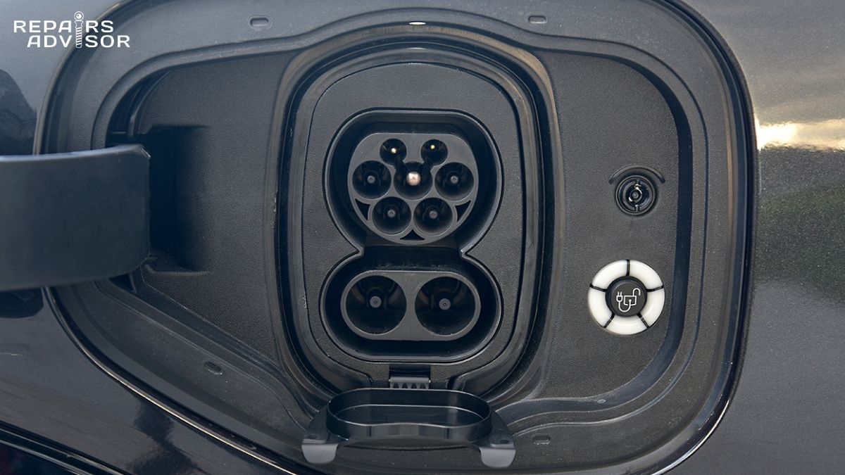
The tradeoff is that without the onboard charger acting as a safety buffer, something else must manage current flow, monitor battery conditions, and prevent damage. That role falls to the vehicle’s Battery Management System and the communication protocols connecting it to the charger. The EV charging port is the physical interface where this conversation begins — its pins carry not just power but the control signals that govern the entire session.
One additional variable is battery voltage architecture. Most current EVs use a 400V battery system. A growing number of newer platforms — including vehicles from Hyundai’s 800V lineup and various new entrants — use 800V architecture. Higher voltage means the same power level can be delivered at lower current, which reduces resistive losses and allows thinner, lighter charging cables. The control protocols handle both architectures, but a vehicle and charger must negotiate compatible voltage and current parameters before charging begins.
The Handshake: How Vehicle and Charger Communicate
Before any high-voltage power flows, the vehicle and charger must establish communication, verify safety, and agree on charging parameters. This process happens in a defined sequence, and it differs depending on which charging standard the vehicle uses.
Control Pilot Signal and Basic Signalling
The first thing that happens when a DC fast charging cable is connected is a low-level safety check using the Control Pilot (CP) pin. This is a signal pin present in all charging connectors — it carries a PWM (pulse-width modulated) signal from the charger to the vehicle. The duty cycle of the PWM signal communicates the charger’s available current capacity. The vehicle responds by pulling the CP line to a defined voltage level, indicating it’s ready to proceed. A proximity detection circuit on a separate pin confirms the connector is fully latched.
This basic signalling layer is defined by IEC 61851 and works the same regardless of whether the vehicle uses CCS, CHAdeMO, or NACS. It’s the foundation everything else builds on.
High-Level Communication: CCS and ISO 15118
For CCS (Combined Charging System) vehicles — which now dominate North America and Europe — the control pilot pin carries more than just PWM. A high-frequency data signal is modulated on top of the CP line using Power Line Communication (PLC), specifically the HomePlug GreenPHY protocol. This channel carries the ISO 15118 or DIN 70121 message set: the structured digital dialogue between the vehicle’s EV Communication Controller (EVCC) and the charger’s Supply Equipment Communication Controller (SECC).
The messages exchanged include the vehicle’s current battery voltage, maximum charge voltage, maximum charge current, target charge voltage, requested current, state of charge, battery temperature, and various status and fault flags. The charger responds with its available voltage and current, and the two systems agree on parameters before the main contactors close. This negotiation continues throughout the session — the BMS updates its current request dynamically, and the charger adjusts output accordingly.
ISO 15118 also enables “Plug and Charge,” where the vehicle presents a digital certificate to the charger, enabling automatic authentication and billing without an RFID card or app. Several model year 2021–2024 vehicles support this including the Porsche Taycan, Hyundai Ioniq 5/6, and BMW i-series models. The vehicle’s network architecture plays a role here — the EVCC must communicate with the BMS and other vehicle controllers to provide accurate real-time data to the charger.
CHAdeMO: CAN-Based Communication
Older CHAdeMO vehicles — including earlier Nissan Leaf models — use a different communication path. Instead of PLC over the CP pin, CHAdeMO uses a dedicated CAN bus connection on COM1 and COM2 pins in the larger CHAdeMO connector. The protocol operates in a master-slave model where the vehicle’s BMS acts as the controller, sending current requests to the charger and receiving status messages in return. The BMS updates its current demand approximately every 100 milliseconds.
CHAdeMO has largely been superseded by CCS in North America and Europe, though it remains common in Japan and on legacy platforms. Understanding the distinction matters for diagnostics: a CCS communication fault will involve the CP/PLC path, while a CHAdeMO fault points to the CAN circuit.
NACS
The North American Charging Standard (SAE J3400, formerly the Tesla connector) uses the same ISO 15118 protocol layer as CCS — Power Line Communication over the control pilot. The physical connector is different and more compact, but from a control logic standpoint, NACS and CCS speak the same language. This compatibility is why adapter solutions between the two standards are practical. Tesla vehicles built before 2021 used a proprietary single-wire CAN protocol rather than ISO 15118; later models support both.
Pre-Charge Sequence and Contactor Control
⚠️ HIGH VOLTAGE HAZARD: The following section describes the operation of 400–800V DC circuits. This information is provided for educational purposes only. DC fast charging system components — including contactors, the pre-charge circuit, and all HV wiring — must only be inspected, tested, or serviced by certified high-voltage technicians with appropriate PPE, training, and equipment. Do not attempt to access these components without proper credentials and isolation procedures.
Once communication is established, the physical charging path must be connected safely. This is where the pre-charge circuit and high-voltage contactors come in — and where a misunderstood sequence can cause serious hardware damage.
Why Pre-Charge Matters
Inside the EV’s power electronics — specifically the motor controller inverter — there are large DC bus capacitors. These capacitors smooth the high-voltage supply and are essential for inverter operation. When the vehicle is powered down or has been sitting, these capacitors discharge. When the DC charge circuit is connected, the battery bus voltage (400V or 800V) appears at the charger output side of the contactor.
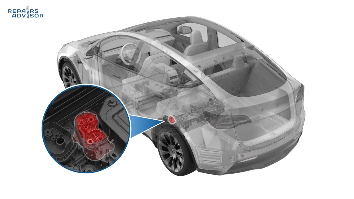
If the main positive contactor closes directly onto discharged capacitors, the resulting inrush current is enormous — equivalent to a short circuit for a brief moment. This current spike can weld the contactor contacts permanently closed, damage the capacitors, and destroy other power electronics. A welded positive main contactor produces fault codes like P2BC5 (Battery Charging System Positive Contactor B Stuck Closed) and will prevent DC fast charging on any subsequent attempt while potentially allowing Level 2 AC charging to continue working normally.
The pre-charge circuit prevents this. It consists of a pre-charge contactor wired in series with a current-limiting resistor, connected in parallel with the main positive contactor. The sequence works as follows:
First, the BMS checks the High Voltage Interlock Loop (HVIL) to confirm all HV connectors are properly seated and no covers have been removed. If the HVIL is intact, the negative main contactor closes, establishing the return path. Then the pre-charge contactor closes, allowing current to flow through the limiting resistor and gradually charge the bus capacitors. The BMS monitors the voltage rise across the capacitor bank. Once the voltage difference between the battery and the capacitor bus drops below a defined threshold — typically 50V or 10% of battery voltage — the main positive contactor closes and the pre-charge contactor opens. The DC charge path is now fully established.
At that point, the BMS commands the charger — via the CCS or CHAdeMO protocol — to begin ramping up current from zero. This controlled ramp prevents additional inrush transients as the system comes under load.
Active Power Negotiation and the CC-CV Charging Curve
Once the contactors are closed and the charger begins delivering power, the session enters active power negotiation. This is the dynamic phase where the BMS continuously updates its current demand and the charger adjusts its output to match — not a fixed process, but an ongoing conversation.
The charging curve follows two distinct phases: Constant Current (CC) and Constant Voltage (CV). In the CC phase, the BMS requests the maximum current it can safely accept given the battery’s current state of charge and temperature. The charger delivers that current, and as the cells fill, their voltage rises. This is the fast part of the charge session — the majority of range is recovered here.
As the battery approaches its upper voltage limit, the BMS transitions to CV. It begins reducing its current request to keep cell voltage from exceeding the maximum threshold. The charger holds voltage steady while current tapers. This is why the charge rate shown on the dashboard slows noticeably above roughly 80% state of charge — the system is deliberately throttling to protect long-term cell life, not malfunctioning. Battery thermal management plays a direct role throughout both phases: if pack temperature rises above a programmed threshold, the BMS reduces its current request. Cold batteries face the same constraint — lithium cells have higher internal resistance at low temperatures, and charging them aggressively when cold accelerates degradation.
For a deeper understanding of the battery system behind these control decisions, the hybrid and EV battery management architecture explains how cell monitoring and balancing integrate with charge control decisions.
Insulation Monitoring During DC Fast Charging
One aspect of DC fast charging control that rarely gets explained is what’s happening on the safety monitoring side throughout the session. Unlike AC charging, where the grid and vehicle are separated by the onboard charger’s transformer, DC fast charging creates a direct galvanic connection between the charging station’s HV output and the vehicle’s battery bus. This means any insulation degradation in the HV circuit — chafed cable, water ingress into a connector, a developing internal fault — creates a genuine shock risk.
The isolation monitoring device (IMD) continuously measures the insulation resistance between HV conductors and the vehicle chassis during the charging session. The minimum acceptable insulation resistance for a 400V system is typically 100 Ω per volt, meaning the total resistance from the HV bus to chassis ground must remain above approximately 40 kΩ. If it falls below this threshold — indicating developing insulation breakdown — the IMD triggers a fault condition. The BMS sends a stop-charging command to the charger via the control protocol, the contactors open, and the session terminates.
Most DC fast chargers perform their own output isolation test before allowing the session to begin, and many monitor it continuously from the charger side as well. A session that terminates unexpectedly with no driver-visible reason often traces back to an insulation fault that briefly dipped below threshold. Pyro-fuse systems represent the last line of defence in severe HV fault scenarios — they trigger on crash detection or a catastrophic short circuit event, physically severing the HV bus connection in microseconds.
Common DC Fast Charging Faults and What They Mean
⚠️ Safety note: The fault information below is provided for educational understanding. Diagnosing or accessing any component in the DC charging path involves 400–800V circuits. All hands-on diagnosis and component work must be performed by certified high-voltage technicians.
DC fast charging faults can be confusing because the symptom — “car won’t charge” — covers a wide range of causes. The most useful first diagnostic step for any technician is establishing whether the vehicle charges normally on Level 2 AC. If it does, the onboard charger and its supporting circuits are working. The fault is isolated to the DC charge path: the DC charge port pins, the communication circuit, the pre-charge circuit, or the main DC contactors.
Common Fault Patterns
A vehicle that charges on AC but fails consistently on DC fast charging at multiple stations most commonly points to a contactor fault — either a stuck contactor (welded closed from prior inrush damage) or a contactor that won’t close due to a drive circuit fault. P2BC5 and P2BC7 are typical DTC signatures for this failure mode. Another possibility is a fault in the communication module: if the vehicle’s EVCC cannot establish PLC communication with the charger’s SECC, the charger will report “vehicle not responding” and decline to deliver power. This points to U-code network communication faults, and checking the 12V auxiliary battery condition is an important first step — a low auxiliary battery can prevent the HV system from completing its wake-up sequence, which prevents the communication controller from initialising.
The DC-DC converter is worth mentioning here: it steps the HV battery voltage down to 12V to maintain the auxiliary battery and power the low-voltage control systems. A degraded DC-DC converter output can cause the 12V system to sag when HV loads are active, causing intermittent communication faults that are difficult to reproduce. Similarly, the motor controller contains the bus capacitors involved in the pre-charge sequence — an internal capacitor failure can produce pre-charge timeout faults even when the contactor hardware itself is intact.
A session that starts and then terminates after a few percent of charge has been added typically points to thermal management or insulation monitoring. The battery may be entering a thermal limit, or a developing insulation fault is crossing the threshold once current begins flowing. If the same vehicle charges normally on a cold day but faults on a hot day, thermal management is the likely culprit. Fault codes involving IMD threshold violations or cooling circuit faults will confirm this direction.
Compatibility issues — where a vehicle charges at some stations but not others — are increasingly common during the NACS/CCS transition period. They usually trace to protocol version mismatches, firmware compatibility between the vehicle and EVSE, or actual connector standard differences requiring an adapter.
DC Fast Charging Control: What It Means for Owners and Technicians
DC fast charging control is not a single component — it’s a system layer that integrates communication protocols, contactor sequencing, BMS feedback, thermal management decisions, and continuous safety monitoring into a real-time control loop operating at hundreds of milliseconds. When it works, the driver sees a charging rate and a countdown. When it doesn’t, the fault can originate from half a dozen different subsystems.
For owners, understanding the control logic makes charging behaviour predictable rather than mysterious. Slower charging above 80% is by design, not a fault. Charging speed varying with ambient temperature reflects the BMS protecting cell longevity. A session that stops and restarts after cooling the battery is the thermal management system doing its job.
For technicians, the system’s logical architecture makes fault isolation tractable: AC-only charging failure points to the OBC; DC-only failure points to the DC charge path; failures at all power levels suggest communication or BMS-level issues. Each vehicle’s factory repair manual provides the specific protocol timing diagrams, contactor resistance specifications, insulation resistance test procedures, and DTC definitions needed for professional-level diagnosis. Browse EV and hybrid repair manuals for your specific vehicle to access the manufacturer-specified procedures for DC charging system diagnosis and component testing.
⚠️ HIGH VOLTAGE HAZARD: DC fast charging systems operate at 400–800V DC. This content is educational. Any diagnostic or service work on DC charging hardware — including the charge port, HV wiring, contactors, pre-charge circuit, or battery management system — must be performed by trained, certified high-voltage technicians using appropriate insulated tools, PPE, and isolation procedures. Consult a qualified EV service facility for any hands-on work.
DC Fast Charging Control: Frequently Asked Questions
EV owners and technicians alike run into the same set of questions about DC fast charging: why does it slow down before 100%, why does cold weather cut charging speed in half, and what actually happens in those first few seconds after you plug in? These questions all come back to the same thing — the control system that runs every DC fast charging session. The answers below cover the most common questions about how DC fast charging control works, what influences charging speed, and what to do when a session doesn’t behave as expected.
Quick Answer
DC fast charging control is the system of protocols, hardware, and battery management logic that governs how a DC charger delivers high-voltage power directly to an EV battery. It handles the initial handshake between vehicle and charger, manages pre-charge sequencing to protect high-voltage contactors, dynamically adjusts current based on battery temperature and state of charge, and monitors insulation integrity throughout the session. For a full technical explanation of how the system works end-to-end, see How DC Fast Charging Control Works.
What is the difference between DC fast charging and AC charging?
The core difference is where the AC-to-DC conversion happens. Every EV battery stores energy as direct current, but the electrical grid delivers alternating current. With Level 1 or Level 2 AC charging, the vehicle’s onboard charger handles the conversion internally — which is why AC charging is limited to roughly 7–22 kW depending on the vehicle. DC fast charging skips the onboard charger entirely: the charging station converts grid AC to DC before it reaches the vehicle and delivers that DC power directly to the battery pack. Because the conversion happens in the much larger, more powerful station hardware, DC fast charging can deliver 50–350 kW or more. The tradeoff is that the vehicle’s Battery Management System and the charger must actively communicate throughout the session to manage current, voltage, and safety — roles the onboard charger handles automatically during AC charging.
Why does DC fast charging slow down above 80% state of charge?
This is normal and intentional — it is the charging control system doing exactly what it is designed to do. DC fast charging follows a two-phase curve. In the Constant Current (CC) phase, the BMS requests maximum current and the charger delivers it, causing battery voltage to rise as cells fill. When the battery voltage approaches its upper limit, the system transitions to a Constant Voltage (CV) phase: the BMS progressively reduces its current request to prevent cell voltage from overshooting the maximum threshold, which would damage the battery. This taper begins noticeably around 80% state of charge on most vehicles and continues until the session ends.
The slowdown protects long-term battery health — pushing lithium cells hard at high states of charge accelerates degradation. The taper rate is set by the vehicle’s BMS, not the station, so plugging into a 350 kW charger will not make it go faster above 80%. Battery thermal management also plays a role: if pack temperature rises during a long fast-charge session, the BMS may begin reducing current demand before 80% is reached.
Does DC fast charging damage the battery?
Modern DC fast charging has a much smaller effect on long-term battery health than early concerns suggested. Multiple large-scale studies — including Recurrent’s 2024 analysis of over 13,000 Tesla vehicles — found no statistically significant range difference between vehicles that used DC fast charging for the majority of sessions versus those that rarely used it. Where DC fast charging does show a measurable effect, it is small: research estimates around 0.1% additional capacity loss per year compared to AC-only charging.
The primary risk factor is heat, not the DC current itself. DC fast charging generates more heat in the battery than AC charging, and the combination of high ambient temperature plus frequent fast charging is more stressful than fast charging alone. Most modern EVs actively manage this with battery thermal management systems that cool the pack during charging. For everyday use, Level 2 AC charging is gentler on the battery and sufficient for most needs. DC fast charging is the right tool for road trips and time-sensitive top-ups — using it regularly but not exclusively is a reasonable approach.
Why does DC fast charging sometimes charge slower than the station’s rated power?
Several factors determine the actual charge rate, and the station’s rated output is only a ceiling — not a guarantee.
A few things can reduce the actual rate below the station’s ceiling. The vehicle’s maximum DC charge acceptance rate is the hard limit — if a car can only accept 100 kW, a 150 kW station will cap at 100 kW regardless. Battery state of charge matters too: charging is fastest between roughly 20–80%, and tapers at both extremes. Temperature is often the biggest constraint in practice; lithium cells have higher internal resistance when cold, and some vehicles block DC fast charging entirely below around −10°C to prevent lithium plating damage. Power sharing cuts available power further when multiple vehicles are charging at the same station simultaneously — many stations split their total capacity across dispensers rather than offering full rated power at each. Finally, battery degradation gradually reduces a pack’s charge acceptance rate as the vehicle ages.
Why does DC fast charging fail in cold weather?
Cold batteries cannot accept DC fast charging at normal rates because low temperatures increase the internal resistance of lithium cells and risk a form of damage called lithium plating, where lithium deposits on the anode surface rather than inserting into it properly. To prevent this, the BMS reduces or blocks DC fast charging below certain temperature thresholds — typically beginning to throttle below around 5°C and potentially refusing DC fast charging entirely below −10°C.
The practical fix is battery preconditioning: many EVs allow you to activate this via the car’s navigation or the manufacturer’s app before arrival at a charger. Preconditioning runs the thermal management system to warm the battery to an optimal charging temperature range, typically 15–25°C, before the session begins. Keeping the vehicle plugged into a Level 2 AC charger overnight in cold weather also helps — the car maintains battery temperature using grid power rather than drawing from the pack.
What does the vehicle and charger communicate during a DC fast charging session?
Quite a lot. Once the connector is plugged in and the Control Pilot signal confirms the connection, the vehicle and charger establish a data channel — either Power Line Communication (PLC) over the Control Pilot pin for CCS and NACS vehicles, or a CAN bus connection for CHAdeMO vehicles. Through this channel, the vehicle sends the charger its current battery voltage, maximum charge voltage, maximum charge current, target charge voltage, current demand, state of charge, battery temperature, and various status and fault flags.
The charger responds with its available voltage and current parameters, and both systems agree on a charging profile before the main contactors close. This dialogue continues throughout the session — the BMS updates its current request dynamically and the charger adjusts output to match. It is a real-time negotiation, not a one-time handshake. Understanding how this communication interfaces with the rest of the vehicle’s electronics is covered in detail in the article on vehicle communication networks.
Why does the session start normally and then stop after a few percent of charge?
A session that begins successfully and then terminates after a small amount of charge has been added typically points to one of three causes. First, a thermal limit: the battery temperature rose quickly once current started flowing and crossed a BMS threshold, triggering a protective shutdown. This is more common with an already-warm battery or in hot ambient conditions. Second, an insulation fault: the isolation monitoring device detected that insulation resistance between HV conductors and the vehicle chassis dropped below the minimum threshold once the circuit was energised. This can happen with developing HV cable damage or moisture in a connector. Third, a communication dropout: the digital handshake between vehicle and charger lost sync mid-session, causing one side to terminate the session as a safety measure.
If the same vehicle charges normally at a different station, the fault is more likely session management or communication incompatibility at that specific charger. If the fault repeats across multiple different stations, the vehicle should be diagnosed by a qualified technician. Checking for U-code (network communication) DTCs is a useful starting point, as is confirming the 12V auxiliary battery condition — a weak auxiliary battery can cause intermittent communication failures during the power demands of a DC fast charging session.
My car charges fine on Level 2 but fails on every DC fast charger. What’s happening?
This symptom pattern is one of the most diagnostically useful in EV charging. Because DC fast charging completely bypasses the onboard charger, a vehicle that charges normally on AC but fails on DC has an intact onboard charger — the fault is isolated to the DC charge path. The most common causes include a stuck or damaged DC contactor (either welded closed from a prior inrush event or failing to close due to a drive circuit fault), a fault in the pre-charge circuit, a faulty charge port temperature sensor blocking DC sessions as a safety measure, or a communication module fault preventing the CCS or CHAdeMO handshake from completing.
Relevant DTCs will typically include P2BC5 or P2BC7 for contactor faults, or U-codes for communication failures. ⚠️ All diagnostic and component work on the DC charging path involves 400–800V circuits and must be performed by certified high-voltage technicians with appropriate PPE and isolation equipment. The HV contactor system and the charging port assembly are both components within this HV circuit. Factory repair manuals for your specific vehicle provide the protocol-level test procedures and contactor specifications required for accurate diagnosis. Browse EV and hybrid repair manuals to find the right manual for your vehicle.
Is it safe to leave an EV connected to a DC fast charger once charging is complete?
Most EVs will stop the charging session automatically once the battery reaches the target state of charge — the BMS sends a stop command to the charger via the control protocol and the contactors open. The physical connector remains locked in place for safety until the session is properly closed. Leaving the vehicle connected after the session ends is generally fine and does not continue to charge the battery, though some networks begin idle fees after a grace period to encourage drivers to free up the station for other users.
One practical note: DC fast chargers should be stopped through the vehicle controls or charger screen before unplugging — physically pulling a connector out of a locked DC port while a session is still active can throw fault codes and sometimes prevents the car from starting a new charge session until the error clears. End the session first, wait for the latch to release, then remove the connector.