When you press the start button on a modern electric or hybrid vehicle, a quiet but precisely orchestrated sequence fires inside the battery pack before a single watt reaches the motor. High voltage contactors — heavy-duty electromechanical switches rated for hundreds of volts and hundreds of amps — close in a controlled order, connecting the traction battery to the drive system in a way that protects both the hardware and anyone working near it. Understanding how HV contactors work helps owners decode BMS fault codes and “not ready” warnings, gives intermediate enthusiasts a clearer picture of EV high-voltage architecture, and gives technicians the diagnostic context to work systematically through contactor-related failures.
⚠️ HIGH VOLTAGE HAZARD — SAFETY-4: HV contactors are located inside or adjacent to the traction battery pack and operate at 48V–800V DC. All service, diagnosis, and replacement work requires a certified high-voltage technician, OEM-specific lockout/tagout procedures, Class 0 insulated gloves rated for the system voltage, and a CAT III 1000V-rated meter. This article is for educational purposes only. Do not attempt to inspect, test, or replace HV contactors without appropriate training and equipment.
Quick Answer
An HV contactor is a high-power electromechanical switch inside the battery pack of an EV or hybrid. The Battery Management System (BMS) opens and closes it to connect or isolate the traction battery from the drive system. Contactors default to the open (safe) position and close in a precise precharge sequence at startup to prevent damaging current surges. Failure most commonly presents as welded contacts (from inrush current arcing), stuck-open contacts (from coil circuit faults), or a vehicle that won’t enter READY mode — all requiring professional diagnosis with OEM-level tools.
What Is an HV Contactor?
Relay vs. Contactor — What’s the Difference?
Both relays and contactors operate on the same principle: a low-voltage coil generates a magnetic field that pulls a movable contact toward a fixed contact, completing a higher-power circuit. The difference is scale. Relays are used in low-to-medium power applications. Contactors are the high-power variant, engineered to safely switch the extreme currents and voltages found in EV traction systems — typically 48V to 800V DC, carrying 100A to 600A continuously, with some heavy-duty variants rated above 1,000A for commercial vehicle applications.
In an HV contactor, the coil is energised by the vehicle’s 12V low-voltage circuit, under the control of the BMS or Vehicle Control Unit. A relatively simple 12V signal commands a circuit carrying several hundred volts and hundreds of amps. Switching DC at these levels produces a persistent arc when contacts separate — unlike AC, which self-extinguishes at its zero-crossing point. To suppress this, most EV contactors use a sealed, gas-filled ceramic arc chamber (typically nitrogen or hydrogen) that rapidly quenches the arc before it can erode the contact surface. By default, all main HV contactors rest in the normally open (NO) position: the HV circuit stays broken until the BMS actively commands closure.
Where HV Contactors Live in the Vehicle
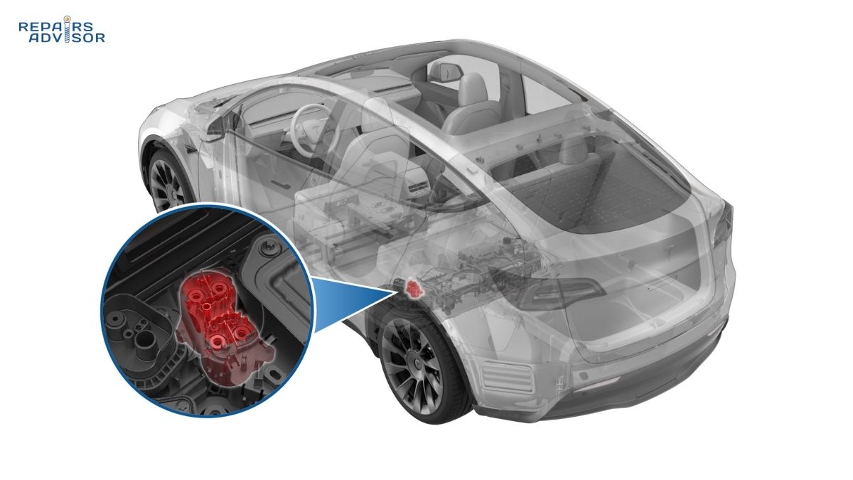
HV contactors live inside the Battery Disconnect Unit (BDU) — sometimes called the high-voltage junction box — which is typically integrated into or mounted directly adjacent to the traction battery pack. The BDU consolidates the contactors, precharge circuit, HV fusing, and voltage measurement points into a single serviceable assembly. From the BDU, orange high-voltage cables run to the electric motor controller and inverter, the onboard or DC fast charger circuit, and the DC-DC converter that keeps the 12V auxiliary battery charged. The BDU is the nerve centre of the hybrid and EV battery system’s power distribution — understanding its role is the starting point for making sense of contactor function and faults.
Types of HV Contactors and Their Roles
Main Positive and Negative Contactors (K+ and K–)
Every EV and hybrid traction battery includes at least two main contactors: one on the positive leg (K+) and one on the negative leg (K–). Together, these provide the primary isolation between the battery pack and everything downstream. When both are open, the HV circuit is completely broken regardless of what happens elsewhere. When they close in the correct sequence, the traction battery powers the inverter, motor, charger, and all other HV loads.
The main contactors also serve as the safety break of last resort. In a collision, thermal runaway, or severe electrical fault, the BMS commands them open immediately. In extreme scenarios — a direct short-circuit — they may be called upon to interrupt the battery’s full fault-level current. This is a one-time, destructive operation. Any contactor that has broken a fault-level short must be replaced before the vehicle returns to service, as the contact surface will have been damaged by the interruption arc.
The Precharge Contactor and Resistor
Wired in parallel with the main positive contactor (K+) is a smaller precharge contactor in series with a current-limiting resistor — typically between 30Ω and 100Ω. This circuit exists for one critical purpose: preventing the DC-link capacitors inside the motor inverter from drawing a catastrophic inrush current surge the moment the main contactors close.
When a fully discharged capacitor suddenly connects to a high-voltage battery, it momentarily behaves like a dead short. Without precharge, that inrush can spike to 1,500A–3,000A or higher — easily enough to weld the main contactor contacts permanently closed, blow the HV fuse, and damage the inverter’s capacitors in the same event. The precharge resistor limits the inrush to a controlled ramp by slowing the capacitor charging process. Once the capacitors are charged close to battery voltage, the main positive contactor closes at negligible differential voltage — no arc, no welding — and the precharge contactor opens.
Charger Contactors and Auxiliary Contactors
Beyond the main pair and precharge circuit, most modern EVs include additional contactors for specific functions. Charger contactors isolate the traction battery from the AC onboard charger when using Level 1 or Level 2 power, and separate contactors handle the DC fast charging path for CCS and CHAdeMO-equipped vehicles. Auxiliary contactors switch HV accessories — PTC cabin heaters, high-voltage air conditioning compressors, and other loads that draw directly from the traction battery rather than the 12V system. Each set of contactors operates independently under BMS control, and faults in any one circuit produce distinct diagnostic signatures.
The Precharge Sequence — How Contactors Close Safely
Step-by-Step Power-Up Sequence
The sequence in which contactors close at startup isn’t arbitrary — it’s a carefully engineered process designed to eliminate the conditions that cause contact welding and hardware damage. The BMS orchestrates every step and aborts the sequence (logging a fault code) if any step fails to confirm correctly.
Here’s how the standard power-up sequence runs:
- BMS self-check — the low-voltage system wakes, the BMS completes its pre-start diagnosis, and confirms no existing faults before any HV circuit is permitted to energise.
- K– closes (negative main contactor) — the circuit remains open because the positive leg is still disconnected; no arc can form at K– because there’s no complete current path yet.
- Precharge contactor closes — current flows from the battery through the limiting resistor and into the inverter’s DC-link capacitors. The BMS now monitors the capacitor voltage rising toward pack voltage.
- Voltage confirmation — once the voltage differential between the battery and the capacitor drops to approximately 50V or less (typically ≥90–95% of pack voltage), precharge is complete.
- K+ closes (positive main contactor) — because capacitor voltage now closely matches battery voltage, the differential at the moment K+ closes is tiny; inrush current is negligible. No arc. No welding.
- Precharge contactor opens — the resistor is removed from the circuit, full power flows through K+, and the vehicle enters READY mode.
Why Sequence Order Matters
Skipping or mis-sequencing any step creates dangerous conditions. Closing K+ before K– means an arc forms at K+ the moment it contacts, since the capacitor is entirely uncharged. Skipping precharge and closing both main contactors simultaneously subjects the contacts to thousands of amps of inrush — virtually guaranteeing that arcing during the contact bounce phase (the brief moment contacts bounce open and closed again as they first engage) will fuse the surfaces together. The BMS monitors voltage at multiple circuit points and aborts the sequence if the precharge curve doesn’t follow expected behaviour — a flat 0V indicates an open precharge path, while a curve stalling at roughly 50% of pack voltage often points to an HV load drawing current during the test or an intermittent precharge contactor.
Precharge Time and RC Constants
The precharge duration is set by the RC time constant of the circuit — the product of the resistor value (R) and total DC-link capacitance (C). One time constant brings the capacitor to about 63% of supply voltage; reaching ≥99% takes five time constants. As a practical example, a system with 6 millifarads of DC-link capacitance and a 50Ω precharge resistor completes precharge in approximately 1.5 seconds. Modern BMS units confirm precharge completion by monitoring the actual voltage rise rather than relying on a fixed timer — a more reliable method that also detects faults like partial shorts or leakage currents that would stall or slow the voltage ramp.
How the BMS Controls HV Contactors
The BMS as Contactor Gatekeeper
The Battery Management System is the sole authority over every contactor in the vehicle. Before it permits any contactor to close, it runs pre-closure checks. The most important is verifying the High Voltage Interlock Loop (HVIL) is intact — the continuous low-voltage monitoring loop running in series through every HV connector and component in the vehicle. If any HV connector is open, damaged, or improperly seated, the HVIL breaks and the BMS refuses to energise the contactors, keeping the HV circuit from going live with an exposed or unsecured connection present.
Simultaneously, the BMS receives data from the isolation monitoring device (IMD), which measures insulation resistance between the HV circuit and the vehicle chassis. If insulation resistance drops below a safe threshold — indicating high voltage may be leaking toward touchable metal — the BMS opens the contactors immediately, even mid-drive, causing an intentional loss of propulsion as a safety action.
Contactor States and BMS Logic
The normally open default state is fundamental to the safety design. A de-energised contactor is a safe contactor — any loss of power to the coil circuit causes it to open, which is the correct failsafe rather than a dangerous condition. Power-down always opens all contactors, disconnecting the traction battery from everything downstream.
Most main contactors include auxiliary contacts — a small secondary contact set mechanically linked to the main contact arm, reporting the actual physical position of the contacts back to the BMS via a separate low-voltage signal. This lets the BMS detect discrepancies between what it commanded and what actually happened. If it commands K+ to open but the auxiliary feedback still shows closed, it registers a welded contact fault. If it commands K+ to close but feedback shows open, it registers stuck open. Either condition prevents normal operation and triggers a stored DTC requiring professional diagnosis.
HV Contactor Failure Modes
Welded Closed (Stuck Closed)
Welded contacts are the most common catastrophic HV contactor failure, and the root cause is almost always excessive inrush current — typically from a failed or degraded precharge circuit. When contacts close against a large voltage differential, arcing occurs during the contact bounce phase. If the arc current is high enough and the bounce lasts long enough, the arc melts the contact material and the surfaces fuse together as they cool. The contacts are now physically bonded in the closed position.
The failure is often discovered not at the moment of welding, but later — when the BMS commands the contactor to open and the auxiliary feedback reports that it hasn’t. A welded main contactor means the battery can no longer be isolated from the drivetrain by that switch alone, creating a serious safety condition. The vehicle may fail to power down correctly, or the BMS may refuse subsequent starts. Before replacing a welded contactor, the precharge circuit — resistor, precharge contactor, and wiring — must be inspected as the probable root cause. Replacing the main contactor without addressing the precharge failure typically results in rapid re-welding. Understanding the DC bus voltage architecture helps clarify why any component drawing unexpected current during startup can precipitate this failure.
Stuck Open (Won’t Close)
A stuck open contactor is commanded to close but remains open — confirmed either by the auxiliary feedback signal or by the absence of expected voltage rise at the DC-link capacitor. The vehicle won’t enter READY mode. Common causes include a blown low-voltage fuse in the coil control circuit, open wiring to the coil, a failed coil winding, a failed BMS output driver, or mechanical failure within the contactor itself.
It’s worth noting that “stuck open” DTCs are sometimes misleading. On Ford Focus Electric vehicles, codes P0AA1 and P0AA0 are frequently triggered not by the contactor itself but by a blown HV fuse on the contactor board — the fuse prevents the contactor from closing, and the BMS interprets this as a stuck contact. Professional diagnosis with OEM scan tools is required to distinguish between these scenarios before any parts are ordered.
Contact Wear and High Resistance
Even without catastrophic welding, HV contacts wear gradually through normal switching. Each closure and opening cycle produces a small arc — the arc when contacts open under load is particularly erosive. Over tens of thousands of cycles, pitting and erosion increase contact resistance. Higher resistance means more heat generated under load (P = I² × R), which can discolour or warp the contactor housing and damage nearby components. Vehicles that frequently use DC fast charging cycle the charging contactors far more intensively than vehicles primarily on overnight Level 2 charging, accelerating wear on those specific contacts. Symptoms include intermittent precharge failures (especially when cold), reduced available power under heavy demand, or a contactor housing that feels warm or appears discoloured after normal use.
Precharge Resistor Failure
The precharge resistor must absorb significant power for 1–3 seconds every startup. An open resistor produces no voltage rise at the capacitor — the BMS sees the precharge voltage stuck at 0V and aborts the sequence. A stuck-closed precharge contactor is potentially more damaging: the resistor, normally energised for under two seconds per cycle, instead carries full HV current continuously, overheating and failing rapidly. Nissan Leaf fault codes C118C and P3176 commonly trace back to precharge resistor failure or contactor faults in the battery junction box, illustrating how OEM-specific codes often point to this subsystem.
Diagnosing HV Contactor Faults
⚠️ SAFETY-4 — All HV contactor diagnostics must be performed by a certified high-voltage technician following OEM-specific lockout/tagout procedures. Class 0 insulated gloves and a CAT III 1000V-rated meter are mandatory. Even with the manual service disconnect removed, DC-link capacitors can retain lethal charge for several minutes. Verify complete HV isolation with a calibrated insulation resistance meter before approaching any HV circuit point.
A Structured Diagnostic Approach
Because contactors are part of a larger interdependent system, the first diagnostic principle is to treat a contactor fault code as a system-level fault until evidence narrows it to the contactor itself. Many contactor DTCs are caused not by the contactor but by something preventing it from closing — a 12V power supply fault, an open HVIL loop, a BMS software inhibit, or a blown HV fuse elsewhere.
A systematic workflow looks like this: Start by pulling DTCs and freeze-frame data — contactor circuit codes, precharge fault codes, and HVIL codes all provide initial direction. Check 12V system health next, since a weak auxiliary battery or poor 12V connection prevents the coil circuits from receiving enough voltage to pull a contactor closed, and this step resolves far more apparent HV faults than its simplicity suggests. Then review live data during a controlled startup attempt, monitoring V1 (pack voltage at battery terminals), V2 (bus voltage on the K– side), and V3 (bus voltage after K+). A precharge curve that rises to 0V indicates an open precharge path. One that stalls at roughly 50% of pack voltage suggests a current drain elsewhere or an intermittent precharge contactor. One that reaches 90%+ but the vehicle still won’t enter READY points to K+ itself failing to close. After that, confirm HVIL loop continuity — an open interlock is a safety feature, not a failure, but it produces identical symptoms. Finally, review auxiliary feedback data from the OEM scan tool to identify any mismatch between the commanded and physical contactor state.
Common DTC Patterns
Several DTC patterns appear repeatedly across platforms. Ford P0AA1 and P0AA0 indicate contactor welded or stuck conditions but are frequently caused by a blown HV fuse on the contactor board rather than a physically welded contact — a distinction that matters considerably for parts ordering. Tesla BMS_u011 points to a precharge handshake fault during DC fast charging, with the precharge contactor, precharge resistor, or arc-pitted main contacts being the most likely culprits. P1D799A indicates an HV battery contactor open due to a release fault, often encountered after a collision triggering the crash signal. Across platforms, generic codes describing “precharge timeout,” “contactor feedback mismatch,” and “welded contact detected” map directly to the failure modes covered above.
HV Contactors Within the Broader Safety Architecture
HV contactors don’t operate in isolation — they’re one layer in a defence-in-depth safety architecture where multiple independent systems work together to prevent high voltage from reaching people or unintended components under any fault condition.
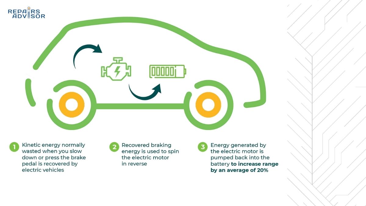
The HVIL loop must confirm all HV connectors are properly seated before the BMS allows contactors to close. The isolation monitoring device runs continuously while contactors are closed, watching for HV-to-chassis leakage that could make the vehicle body electrically live. The pyro-fuse provides crash-activated emergency isolation independent of contactor state — critically important if contactors are welded closed at the moment of impact. The battery thermal management system feeds temperature data to the BMS, which can open contactors if the pack exceeds safe thermal limits. At the other end of the circuit, the traction motor and its inverter depend on the entire contactor system functioning correctly to receive power safely and efficiently. During regenerative braking, recovered energy flows back through the same HV bus the contactors manage — contactor health affects overall EV performance, not just startup reliability.
What Owners and Technicians Should Know
Symptoms That Warrant Professional Evaluation
A vehicle that consistently fails to enter READY mode despite a charged battery — particularly if it occasionally recovers after repeated attempts — may be experiencing intermittent precharge or contactor coil faults. Intermittent “not ready” behaviour on cold mornings can reflect contactors whose coil resistance has shifted with temperature. DC fast charging failures that occur at the very start of a session, before any power transfer begins, often indicate a charging contactor or precharge fault during the DC charging handshake — the pattern behind Tesla’s BMS_u011. Dashboard warnings referencing the high-voltage system or battery, even when the vehicle seems otherwise drivable, should be diagnosed promptly rather than monitored. These often reflect active BMS detection events rather than informational alerts.
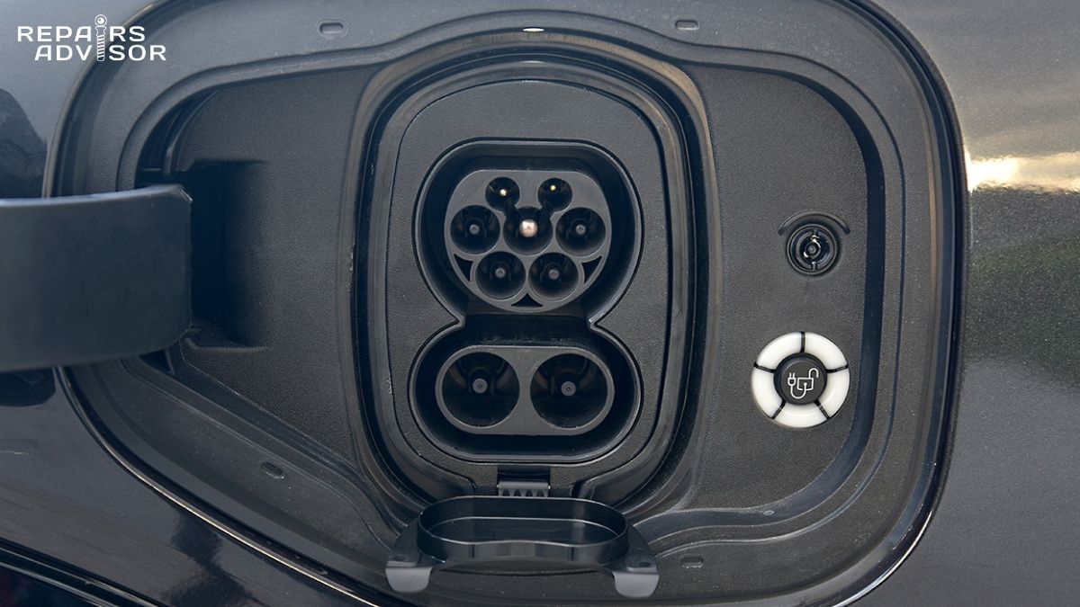
The EV charging port and its associated inlet are the interface where most owners interact with the edge of the HV charging system. While the port itself is safe to handle under normal conditions, charging fault codes appearing alongside HV system warnings should be diagnosed together — they often share a root cause in the contactor or precharge circuit upstream.
Why Professional Service Is Mandatory
HV contactors sit inside or directly adjacent to the traction battery pack. Even after the vehicle is powered down and the manual service disconnect removed, the traction battery retains its full charge. The DC-link capacitors in the inverter can additionally hold lethal voltage for several minutes after isolation. Physical access to the contactors on most platforms requires removing or partially disassembling the battery pack — a significant undertaking involving structural fasteners, HV cable disconnections, and coolant system work on liquid-cooled packs. Functional testing requires OEM scan tools capable of commanding individual contactor actuation and monitoring V1/V2/V3 voltages in real time during startup. This work belongs to certified high-voltage technicians trained to the ASE xEV standard or equivalent OEM certification.
Getting the Right Service Documentation
OEM service manuals for HV contactor work include coil resistance specifications, auxiliary feedback pin locations and resistance values, precharge circuit wiring diagrams, voltage monitoring point specs, and the precise DTC diagnostic trees that translate fault codes into test procedures. Generic aftermarket repair information often lacks the HV-specific detail required for safe and accurate diagnosis. Manufacturer-specific documentation is available for Tesla repair manuals, Toyota repair manuals, and Nissan repair manuals. You can also browse all car repair manuals by make and model to find the documentation for a specific platform.
Understanding HV Contactors — the Foundation of EV Safety
High voltage contactors are deceptively simple in concept but occupy a critical position in EV safety and reliability. Their operation depends on the precharge sequence preventing the very inrush currents that would destroy them. Their integrity depends on the BMS correctly reading auxiliary feedback. Their safety depends on the HVIL, IMD, and pyro-fuse working alongside them as a coordinated system. When they fail, the failure often cascades: a welded contact means a battery that can’t be isolated, and the root cause is usually the missed precharge that produced the weld in the first place. Understanding this interdependence helps owners take BMS warnings seriously and approach HV faults as system-level problems rather than isolated component failures. All contactor service remains SAFETY-4 — certified technicians, OEM procedures, verified isolation, and appropriate PPE, without exception.
HV Contactors: Frequently Asked Questions
High voltage contactors are one of the most misunderstood components in modern electric and hybrid vehicles — quiet, invisible, and almost never mentioned until something goes wrong. These heavy-duty electromechanical switches control whether the traction battery is connected to the rest of the drive system, and their health directly affects whether your vehicle starts, charges, and drives safely. Below are answers to the questions owners and technicians ask most often about HV contactors, their failure modes, and what happens when they go wrong.
⚠️ HIGH VOLTAGE HAZARD — SAFETY-4: HV contactors are part of systems operating at 48V–800V DC. Any inspection, testing, or replacement work must be performed by a certified high-voltage technician following OEM lockout/tagout procedures with appropriate PPE. This FAQ is for educational purposes only.
Quick Answer
HV contactors are high-power electromagnetic switches that connect and isolate the traction battery from the drive system in electric and hybrid vehicles. They close in a specific sequence at startup (controlled by the BMS) and open automatically when the vehicle powers down, detects a fault, or experiences a collision. The most common failure modes are welded contacts (from inrush current) and stuck-open contacts (from coil circuit faults) — both causing a vehicle that won’t enter READY mode. All contactor service is SAFETY-4 and requires certified high-voltage technicians. For a full technical explanation, see the complete HV contactors guide linked at the end of this page.
What does an HV contactor actually do in an electric vehicle?
An HV contactor is the gatekeeper between the traction battery and everything the battery powers — the motor inverter, the charger, the DC-DC converter, and any high-voltage accessories. When the contactor is open, the high-voltage circuit is completely broken; the battery sits safely isolated regardless of what happens elsewhere in the drivetrain. When the contactor closes under BMS command, it connects those circuits and allows power to flow.
Think of it as a very heavy-duty relay. A relay uses a small control current to switch a much larger load current — the same principle applies here, except the “larger load” is several hundred volts and hundreds of amps. The BMS drives the contactor’s coil using the vehicle’s 12V system, so a standard 12V signal controls a circuit that can deliver hundreds of kilowatts to the motor. The contactor’s gas-filled ceramic arc chamber ensures the arc that forms when contacts separate under load is quickly extinguished rather than eroding the contact surfaces.
Beyond startup and shutdown, contactors also serve as the safety disconnect that isolates the battery immediately in fault conditions — insulation failures, HVIL breaks, overtemperature events, or crash signals. They’re central to the hybrid and EV battery system’s ability to be made electrically safe under any operating condition.
How many HV contactors does an electric vehicle have?
Most battery electric vehicles have a minimum of three contactors in the main traction circuit: a main positive contactor (K+), a main negative contactor (K–), and a precharge contactor wired in parallel with K+ through a current-limiting resistor. This three-contactor arrangement is the core of every EV’s high-voltage power-up sequence.
Beyond that baseline, the total count depends on the vehicle’s charging capabilities and HV accessory architecture. A vehicle with DC fast charging capability typically adds a positive and negative charging contactor specifically for the DC charge path — so that charging current doesn’t flow through the main drive contactors. Auxiliary contactors may control high-voltage accessories like PTC cabin heaters and electric air conditioning compressors. A well-equipped modern EV or plug-in hybrid may contain five to eight contactors in total across all its HV circuits. On Tesla Model S/X platforms, four large contactors plus separate charging contactors are documented in owner accounts.
What’s the clicking sound I hear when I start my EV or hybrid?
The soft “clunk-clack” heard from the floor or battery area when starting an EV is the sound of the HV contactors closing during the precharge sequence. It’s entirely normal. Tesla even documents this in their official owner guides, explaining that the thumping sound from the floor when starting after the vehicle has been parked “signifies that the high voltage contactors are closing the circuit between your vehicle and the battery.”
The sequence produces two distinct sounds in many vehicles: the initial click of the precharge contactor and negative main contactor engaging, followed by the heavier clunk of the positive main contactor closing once precharge is complete. Hybrid vehicles like the Ford Maverick and Hyundai Ioniq also produce relay clicking sounds during mode transitions as the system switches between electric and combustion power. This is normal HV relay activity.
What isn’t normal is rapid, repetitive clicking — contactors cycling open and closed every few minutes when parked or plugged in. This can indicate a software issue causing the vehicle to repeatedly wake and sleep (cycling the contactors each time), or a fault that’s preventing stable HV system engagement. Rapid cycling dramatically accelerates contact wear, since contactors are rated for a finite number of switching cycles, typically in the tens of thousands. If you’re hearing unusual or frequent clicking, a professional diagnostic is worthwhile.
Why won’t my EV enter READY mode — could it be the contactor?
A “no READY” condition — where the vehicle powers on but the drivetrain won’t engage — is one of the most common presentations of an HV contactor fault, though the contactor itself may not be the root cause. The BMS enforces a series of checks before it will permit the contactors to close and allow propulsion; if any check fails, the vehicle stays in a powered-but-non-driving state.
Common reasons the BMS refuses to close the contactors — producing a no-READY symptom — include: a weak 12V auxiliary battery that can’t supply enough coil activation current; an open HVIL loop indicating an unseated HV connector; an insulation fault detected by the isolation monitoring device; a precharge circuit fault; or an actual mechanical or electrical failure of the contactor itself. Because so many different faults produce identical symptoms, professional diagnosis with OEM-level scan tools — monitoring live V1/V2/V3 bus voltages during a startup attempt — is required to identify the actual cause.
If the vehicle occasionally enters READY mode after repeated attempts, or recovers after sitting for a few minutes, intermittent precharge failure or a coil circuit fault with marginal connections is the more likely culprit than a fully welded or dead contactor.
What causes HV contactors to weld closed?
Welded contacts are the most common catastrophic contactor failure mode, and the root cause is almost always uncontrolled inrush current — specifically, the enormous surge that occurs when a large, discharged capacitor suddenly connects directly to a high-voltage battery without the current being limited first.
When the main positive contactor closes against a significant voltage differential, the contacts bounce briefly as they first engage — a natural mechanical phenomenon in any relay or contactor. During that bounce, each time the contacts briefly separate, an arc forms across the gap. If the current driving that arc is high enough (potentially 1,500–3,000A or more without precharge), the arc melts the contact surface material. When the contacts finally stop bouncing and stay closed, the molten surfaces cool and fuse together — welded shut.
This is why the precharge circuit is so critical to contactor longevity. A properly functioning precharge circuit raises the inverter capacitor voltage to near-battery voltage before K+ closes, reducing the voltage differential (and therefore the inrush current) to negligible levels at the moment of closure. When the precharge circuit fails — open precharge resistor, stuck-closed precharge contactor, or failed precharge relay — the main contactors absorb all of that inrush energy and weld. High ambient temperatures accelerate wear; frequent DC fast charging adds extra switching cycles on the charging contactors specifically; and high-performance driving with repeated large current surges shortens contact life faster than the manufacturer’s rated cycle count assumes. Any contactor that has welded closed should be treated as a SAFETY-4 situation requiring immediate professional attention — the battery can no longer be cleanly isolated through that switch.
What’s the difference between a welded contactor and a stuck-open contactor?
These are opposite failure modes with different safety implications and different diagnostic signatures.
A welded (stuck-closed) contactor is one that the BMS commands to open but that physically cannot — the contact surfaces are fused together. The auxiliary feedback signal (a small secondary contact that reports actual physical position) shows closed when the BMS expects open. This is a hazardous condition: the vehicle cannot fully isolate its traction battery through that contactor. Symptoms may include the vehicle failing to fully power down, BMS warnings about contactor state mismatch, or the system refusing to allow a new startup sequence. On Ford Focus Electric vehicles, this condition often presents as P0AA1 or P0AA0 — though these codes are frequently triggered by a blown HV fuse preventing closure rather than actual welding.
A stuck-open contactor is one that the BMS commands to close but that fails to do so — the contacts remain open when they should be conducting. The vehicle won’t enter READY mode; the precharge voltage stays at 0V if the stuck contactor is in the precharge path, or the main drive circuit stays dead if K+ itself is stuck. Causes range from a blown low-voltage fuse in the coil circuit, to open wiring, to a failed coil winding, to a mechanical failure within the contactor housing. This is less immediately hazardous than welding (the battery is still isolated), but the vehicle is undrivable.
How long do HV contactors last?
HV contactors are rated for a finite number of electrical switching cycles under specified load conditions — typically in the range of tens of thousands of cycles for main contactors, depending on manufacturer specifications and the currents being switched. Under ideal operating conditions with a properly functioning precharge circuit (meaning minimal arc at each closure), contactors can realistically last the life of the vehicle. The precharge circuit is specifically designed to make the main contactor’s switching duty as gentle as possible.
In practice, the factors that shorten contactor life include: precharge circuit degradation over time (raising inrush at each startup), high-performance driving with repeated large current demands, frequent DC fast charging (more switching cycles on the charging contactors specifically), and extreme temperature conditions. Real-world data shows a wide range — main contactors can fail anywhere from 50,000 miles to well over 100,000 miles depending on usage patterns. Some Tesla Model 3 owners have reported contactor-related repair costs around $700 at approximately 50,000 miles of heavy Supercharging use. One important note regardless of mileage: if a contactor has ever interrupted a full fault-level short-circuit current, it must be replaced — the contact surface will have been damaged by the interruption arc even if the contactor still appears functional.
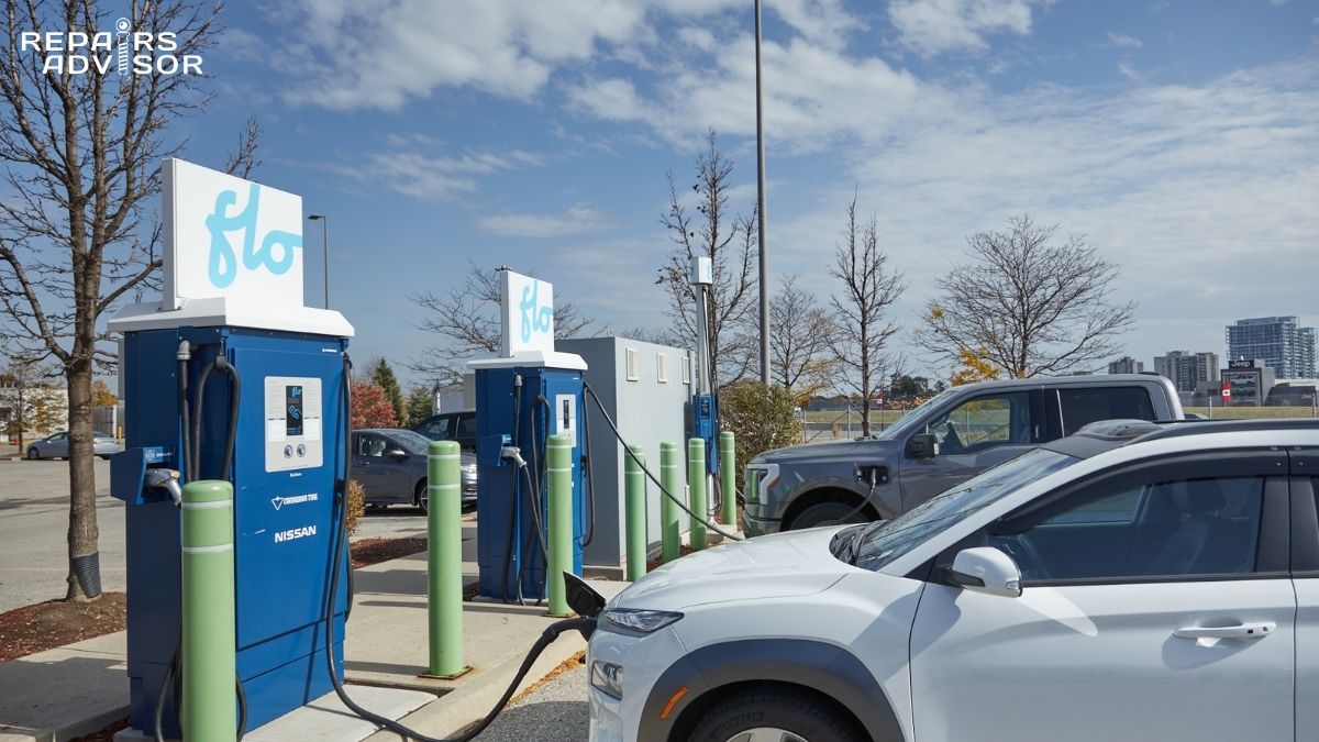
Does DC fast charging wear out the contactors faster?
It can, depending on the vehicle’s architecture. Vehicles that route DC fast charging current through dedicated charging contactors — separate from the main drive contactors — accumulate switching cycles on those charging-specific contactors with each session. A vehicle that relies on DC fast charging for most of its charging accumulates far more switching cycles on those contactors than a vehicle that primarily charges overnight at Level 2. If the charging contactor’s precharge circuit isn’t properly protecting against inrush at session start, each cycle may also produce more arc damage than it should.
The DC fast charging control system involves a handshake and precharge sequence at the start of each session — this is exactly where Tesla’s BMS_u011 fault code can appear if the charging contactor or precharge circuit isn’t completing the voltage ramp correctly. Whether DC fast charging meaningfully shortens overall contactor life depends heavily on whether the precharge circuit is doing its job. A well-maintained system with a fully functional precharge path should accumulate switching cycles at DC fast chargers without significantly accelerating contactor wear beyond normal patterns.
Can I diagnose or replace an HV contactor myself?
No. HV contactor diagnosis and replacement is SAFETY-4 work — it is not appropriate for DIY service regardless of the individual’s general mechanical skill level.
The reasons are both practical and safety-critical. Diagnosis requires OEM-level scan tools capable of commanding individual contactor actuation, monitoring live V1/V2/V3 bus voltages in real time, and reading manufacturer-specific DTCs with their full diagnostic trees. Standard OBD-II scan tools do not provide this capability. Physically accessing the contactors on most platforms requires removing or partially disassembling the traction battery pack — a significant undertaking involving structural fasteners, orange HV cable disconnections, and coolant system work on liquid-cooled packs.
Critically, even with the vehicle powered down and the manual service disconnect removed, the traction battery retains its full stored charge. The DC-link capacitors in the inverter can hold lethal voltage for several minutes after isolation. Approaching these systems without verified HV isolation, Class 0 insulated gloves rated for the system voltage, and a CAT III 1000V-rated meter creates conditions for fatal electrical shock or arc flash injury. This work belongs to certified high-voltage technicians trained to the ASE xEV standard or equivalent OEM certification, following the full OEM lockout/tagout procedure for the specific vehicle platform.
What does a contactor fault code actually mean?
Contactor fault codes are the BMS reporting a discrepancy between what it commanded and what the auxiliary feedback or voltage monitoring confirmed. The code itself identifies which contactor or circuit is involved and what type of mismatch was detected — but it doesn’t always identify the root cause, which is why professional diagnosis is essential before any parts are ordered.
Ford P0AA1 / P0AA0 — These indicate a high-voltage contactor circuit fault (welded or stuck). Despite the name, these codes on Ford Focus Electric vehicles are frequently caused by a blown HV fuse on the contactor board rather than a physically welded contact. The fuse blows, the contactor can’t close, and the BMS interprets this as a stuck contact. Replacing the contactor without checking the fuse and investigating the root cause of the blown fuse typically leads to repeat failure.
Tesla BMS_u011 — This fault appears during DC fast charging when the precharge handshake fails to complete correctly. The system attempts to ramp the charging circuit voltage but doesn’t see the expected rise. Most likely causes in order are: precharge contactor fault, failed or degraded precharge resistor, and arc-pitted main contacts with higher than expected resistance. Mechanical contact wear after high mileage and heavy Supercharging use is a documented real-world cause.
P1D799A — HV battery contactor open due to release fault. Often encountered in vehicles that have experienced a collision or airbag deployment triggering a crash isolation signal. The contactors opened correctly as a safety response, but a stored fault prevents re-engagement until the system is professionally inspected and cleared.
Generic codes describing “precharge timeout,” “contactor feedback mismatch,” or “welded contact detected” appear across platforms and map directly to the failure modes described above. The code is the starting point for diagnosis, not the diagnosis itself.
How does the precharge circuit protect the contactors?
The precharge circuit is the primary mechanism that keeps HV contactors from welding themselves shut on every startup. Without it, the first time a main contactor closes against a discharged inverter capacitor bank, the resulting inrush current — potentially several thousand amps — would arc across the contact surfaces during the natural contact bounce phase and fuse them closed.
The precharge contactor and its series resistor (typically 30–100Ω) are wired in parallel with the main positive contactor. During startup, the BMS closes the precharge contactor first, allowing current to flow through the resistor and slowly charge the inverter’s DC-link capacitors. The BMS monitors the capacitor voltage rising toward battery voltage — typically waiting until the differential falls below 50V, representing roughly 90–95% of pack voltage. Only then does K+ close. Because the voltage on both sides of K+ is now nearly equal, almost no current flows at the moment of closure — no arc, no welding, no damage.
The precharge circuit also acts as an early-warning system. If the voltage ramp stalls (stays at 0V, or rises to about 50% and stops), the BMS detects that something in the downstream circuit isn’t right — a soft short, an unexpected HV load drawing current, or an open in the precharge path itself — and aborts the sequence before the main contactors close into a potentially dangerous condition. Understanding how precharge protects the system is the key to understanding why precharge circuit faults — open resistors, failed relays, stuck-closed precharge contactors — so often precede or cause main contactor welding.
How do HV contactors relate to the HVIL, pyro-fuse, and other safety systems?
HV contactors don’t operate independently — they’re one layer in a coordinated safety architecture where multiple systems work together to prevent high-voltage exposure under any fault condition.
The High Voltage Interlock Loop (HVIL) is a prerequisite for contactor closure. Before the BMS will allow any main contactor to close, it verifies that the HVIL loop — a low-voltage monitoring circuit running through every HV connector in the vehicle — is intact. A single disconnected or improperly seated HV connector breaks the loop, and the BMS refuses to energise the contactors. This prevents the HV circuit from going live with an exposed connection point present.
The isolation monitoring device (IMD) runs continuously while contactors are closed, measuring insulation resistance between the HV circuit and the vehicle chassis. If insulation degrades — from damaged wiring, water intrusion, or component failure — the IMD triggers the BMS to open the contactors immediately, isolating the battery even if this happens mid-drive.
The pyro-fuse provides crash-activated emergency isolation that operates independently of contactor state. In a collision, crash sensors trigger the pyro-fuse to physically sever the HV circuit with a small explosive charge — critically important in scenarios where the contactors may be welded closed and unable to open through BMS command alone. This layer of the safety architecture is what ensures the HV circuit can be made safe even if the contactors have failed.
Together, these systems — contactors, HVIL, IMD, and pyro-fuse — form the complete isolation architecture for a modern EV’s high-voltage battery system. Understanding how they work together is essential context for anyone learning EV diagnostics or evaluating an HV fault.
Where can I find technical documentation for HV contactor service on my vehicle?
OEM service manuals contain the information required for HV contactor diagnosis and replacement: contactor coil resistance specifications, auxiliary feedback contact pin locations and resistance values, BDU wiring diagrams, precharge circuit schematics, V1/V2/V3 test point locations, and the complete DTC diagnostic trees that specify exactly what tests to perform at each fault code. Generic repair information rarely includes HV-specific contactor procedures at the depth required for safe and accurate work.
Manufacturer-specific repair manuals are available for Tesla vehicles, Toyota hybrids and EVs, and Nissan EV platforms including the Leaf. For the full technical background on how HV contactors work, including the precharge sequence, BMS control logic, failure modes, and diagnostic voltage curve methodology, see the complete HV contactors guide. You can also browse all car repair manuals by make and model to locate documentation for a specific platform.