Every modern electric and hybrid vehicle operates with a high-voltage system carrying anywhere from 400 to 800 volts — enough to cause serious injury or death on contact. What keeps occupants safe isn’t luck or physical distance alone. It’s a continuous electronic guardian called the isolation monitoring device (IMD), quietly measuring the barrier between that lethal voltage and the steel chassis you’re sitting in. Understanding how this system works matters whether you’re driving an EV, diagnosing a fault code, or studying the architecture of modern vehicle safety.
Quick Answer
An isolation monitoring device (IMD) is an active safety component in hybrid and electric vehicles that continuously measures the insulation resistance between the high-voltage system and the vehicle chassis. It works by injecting a low-level test signal onto the HV bus and calculating how much current leaks through to chassis ground — a result that directly represents insulation integrity. Most systems trigger a warning when resistance drops below approximately 500 Ω/V and may restrict or de-energize the HV bus at lower thresholds. Isolation fault diagnosis requires a certified high-voltage technician; this is not a DIY repair area.
Why Electrical Isolation Matters in High-Voltage Vehicles
Unlike household wiring, which is grounded to earth, EV and hybrid high-voltage systems use what engineers call an IT (isolated terra or unearthed) network architecture. The entire HV system — battery pack, cables, traction inverter, motor — floats electrically relative to the vehicle chassis. This design is deliberate, and it’s the foundation of EV occupant protection.
Here’s the key principle: a single electrical shock can only occur when current flows through your body from one potential to a lower one. In a properly isolated system, touching a single point in the HV circuit while standing on the chassis won’t complete a circuit — there’s no return path. A person would need to simultaneously contact both a failed positive rail and a failed negative rail, or bridge between the HV system and chassis twice, to receive a dangerous shock. This is called the two-fault tolerance model, and it’s why isolation integrity is treated as a fundamental safety requirement rather than a convenience feature.
The hybrid battery system that powers the vehicle depends on this isolation being maintained at all times — during driving, charging, and even when the vehicle is parked. When insulation anywhere in the HV circuit begins to degrade, the IMD is the first system to catch it.
What Is an Isolation Monitoring Device?
An IMD is a dedicated electronic module that permanently monitors insulation resistance (RF) between the high-voltage bus and the vehicle chassis ground (PE). Unlike the physical insulation on cables and connectors — which is passive and provides no feedback — the IMD actively interrogates the system and reports quantitative resistance values in real time.
The device connects to both the positive and negative high-voltage rails simultaneously, plus the chassis ground reference. This dual-rail connection is essential: it lets the IMD detect both symmetrical faults (where both rails degrade equally relative to chassis) and asymmetrical faults (where only one rail degrades), which require different detection strategies. Standards such as IEC 61557-8 and ISO 6469-3 mandate that IMDs detect both fault types — a requirement that drove significant development in measurement circuit design over the years.
Physically, the IMD is typically a compact module integrated within the battery management system housing or mounted adjacent to the HV junction box. It communicates with the broader vehicle safety architecture through the CAN bus, allowing the BMS and vehicle control unit to act on its data. For more on how that communication layer works, see how vehicle CAN bus networks operate.
How the IMD Measures Insulation Resistance
The Signal Injection Method
The core measurement principle is elegant: the IMD injects a controlled test signal — typically a low-frequency AC or pulsed DC signal at very low current — onto the HV bus. This test signal is completely invisible to the vehicle’s power electronics during normal operation. The IMD then measures how much of that signal current finds its way from the HV rails through the insulation to the chassis ground.
The relationship is direct: more leakage current means lower insulation resistance. The IMD calculates RF using Ohm’s law: RF = V_test ÷ I_leakage. A healthy system shows RF values well above 1 MΩ. As insulation degrades — whether from moisture, heat cycling, or physical damage — RF falls. Most OEM calibrations set a warning threshold at approximately 500 Ω/V (meaning at a 400V system, the warning fires when RF drops below 200 kΩ) and a shutdown or severe restriction threshold at lower values depending on the platform.
Handling Parasitic Capacitance
Modern HV systems introduce a complication: long cable runs, shielded wiring, and EMI suppression capacitors (Y-capacitors) all create parasitic capacitance between the HV system and chassis. This capacitance can interfere with the IMD’s test signal, particularly in 800V architectures where these effects are more pronounced. Modern automotive-grade IMDs — including designs that comply with current IEC 61557-8:2014 specifications — incorporate signal processing algorithms that compensate for parasitic capacitance, allowing accurate RF measurement even in complex system configurations.
The transition from 400V to 800V platforms has been one of the more demanding challenges for IMD manufacturers. Higher voltages mean smaller acceptable leakage currents for the same safety margin, and 800V systems typically have lower total capacitance, which changes the measurement dynamics. This is an area where the relevant international standards are still catching up to production vehicle requirements.
Continuous Monitoring — Including During Charging
A critical design requirement is that the IMD must operate continuously — not just at vehicle startup or during driving. Insulation faults are most likely to develop gradually over time, and some failure modes (such as moisture intrusion) may appear intermittently. Always-on monitoring catches these before they progress to a dangerous level.
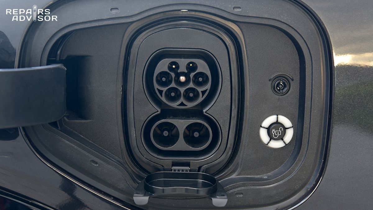
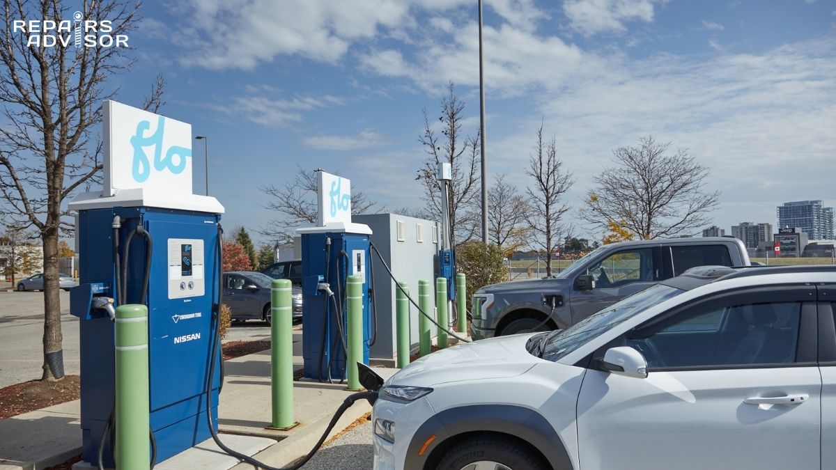
During DC fast charging, the insulation monitoring function takes on additional significance. The charging protocol itself includes an insulation check sequence before high-current power transfer begins — the IMD’s data is part of what authorizes the charger to proceed. For a deeper look at that handshake, see how DC fast charging control and power negotiation work.
IMD Integration With the BMS and HV Safety Architecture
BMS Communication and Response Logic
The IMD doesn’t make safety decisions in isolation — it reports to the battery management system, which holds the decision logic. Most implementations follow a two-threshold model: a warning level that activates a dashboard alert without restricting operation, and a critical level that triggers power limitation or full HV de-energization via the main contactors.
The specific thresholds and response actions vary by OEM and are calibrated to the platform’s voltage level and safety case. Some systems allow continued low-speed operation with an active warning to enable the driver to reach a safe location; others shut down HV operation immediately. The IMD itself typically provides dual fault-state outputs (warning and alarm) that the BMS reads independently of the CAN data stream, providing redundancy in the safety signaling chain.
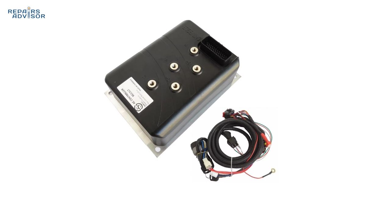
Understanding how the BMS interprets and acts on IMD data requires familiarity with the broader electric motor controller and power electronics architecture of the vehicle, since the IMD’s alarm state directly affects inverter operation.
Layered HV Safety: IMD, HVIL, and Pyro-Fuse
The IMD is one layer in a three-part HV safety stack, and it’s worth understanding what each layer does — and doesn’t do — to avoid diagnostic confusion.
The IMD detects insulation degradation: a slow, progressive failure mode where the resistance between HV conductors and chassis drops over time. It won’t fire on a healthy system that simply has a connector slightly unseated. That’s the job of the high voltage interlock loop (HVIL), which monitors the physical connection integrity of every HV connector in the system. When an HV connector is opened, the HVIL circuit breaks instantaneously and the vehicle disables HV operation — independent of what the IMD is measuring.
The third layer is the pyrotechnic fuse (pyro-fuse), which activates on crash sensor input to physically sever the HV circuit in milliseconds. This operates entirely independently of both the IMD and HVIL — it’s a one-shot mechanical intervention, not an electronic feedback system.
Together, these three systems address different failure modes: insulation degradation (IMD), connector separation (HVIL), and crash events (pyro-fuse). The HV contactors serve as the controllable disconnect that all three systems can command open when their respective conditions are met.
Common Causes of Isolation Faults
When an IMD triggers a fault, the vehicle has detected a real drop in insulation resistance — but finding the source requires systematic investigation. These are the most common root causes technicians encounter.
Moisture and Water Intrusion
Moisture is the most frequent cause of isolation faults in production vehicles. Water intrusion into HV connectors, battery pack enclosures, or cable routing can significantly reduce insulation resistance, even in small amounts. The fault may appear intermittently — present when the vehicle is cold or wet, absent after the system warms up and moisture evaporates. This intermittent pattern is a diagnostic clue pointing toward moisture rather than physical insulation damage.
Wiring and Insulation Degradation
High-voltage cables in EVs and hybrids are routed through areas subject to significant vibration, heat cycling, and mechanical stress. Over time, chafing against chassis components or heat damage near the battery pack or motor can thin or crack insulation. The HV wiring harness is designed with robust shielding and routing protection, but these can be compromised in vehicles with high mileage or after collision repairs where cables may have been disturbed.
Contamination and Internal Battery Faults
Conductive debris inside connectors, electrolyte leakage from a damaged battery cell, or corrosion on HV terminals can all create unintended conductive paths to the chassis. Internal battery pack faults are particularly challenging because they’re enclosed and may not be visible during inspection. The battery thermal management system plays an indirect role here — coolant leaks near the HV pack can contribute to insulation degradation if the coolant contacts conductive components.
Capacitance-Related False Readings
In high-voltage integrated architectures — particularly platforms using e-axle integration where motor, inverter, and gearbox are combined — the proximity of power electronics components can affect IMD readings. This isn’t always a true insulation fault; sometimes it reflects a measurement challenge the IMD’s compensation algorithm needs to handle. Distinguishing a genuine degradation fault from a parasitic capacitance artifact requires systematic sectioning during diagnosis.
Diagnosing Isolation Faults
Safety Warning: High-voltage EV and hybrid systems carry 400V–800V DC. Capacitors in the inverter and DC-DC converter can hold lethal charge even after the vehicle is switched off. All diagnostic and repair work involving HV components must be performed exclusively by certified high-voltage technicians using appropriate PPE (Class 0 insulated gloves minimum), HV-rated insulated tools, and strict OEM lockout/tagout procedures including verified HV de-energization with an approved meter before any contact. This section is provided for educational understanding of the diagnostic process; it is not a guide for unqualified personnel to attempt HV diagnosis.
Reading Fault Codes
The primary isolation-related DTC is P0AA6 — High Voltage System Isolation Fault. This code appears across most EV and hybrid platforms, though OEM-specific variants exist. In some BMS implementations (such as the Orion BMS), P0AA6 is an informational code that does not itself restrict operation — the BMS may still allow charge and discharge while the fault is active. In OEM production vehicles, the response is generally more aggressive. Always retrieve the full DTC list with freeze frame data before drawing conclusions; companion codes from the HVIL system, BMS, or motor controller often narrow the fault location significantly.
Systematic Fault Isolation
Because the IMD measures the entire HV circuit as a single network, it can detect a fault but cannot pinpoint its location. Technicians locate the fault by systematically sectioning the HV circuit — disconnecting subsystems one at a time and monitoring whether the IMD reading recovers. The typical sequence works through: external charger connections, the DC-DC converter, the traction inverter and traction motor assembly, and finally the battery pack itself. The subsystem whose disconnection restores normal RF indicates the fault zone.
Once the fault zone is identified, technicians perform a static insulation resistance test using an approved megohmmeter — only after full HV de-energization and lockout is verified. The OEM service procedure specifies the test voltage and minimum acceptable resistance value for each subsystem.
Post-Repair Validation
Any work involving movement of HV cables, connector servicing, or battery pack removal mandates a full isolation resistance test before HV system reactivation. The IMD must report RF above threshold with the complete system reassembled before the vehicle is cleared for operation. OEM-specific procedures define the exact initialization sequence and acceptance criteria — these differ significantly between platforms. Refer to the appropriate service documentation for Toyota, Tesla, or Nissan vehicles, as each manufacturer has platform-specific calibration thresholds and validation steps.
Regulatory Standards Governing Isolation Monitoring
Isolation monitoring in production vehicles isn’t optional — it’s mandated by multiple overlapping international standards. IEC 61557-8:2014 is the primary technical standard for IMD design, specifying minimum insulation resistance measurement accuracy, response time, and the requirement to detect both symmetrical and asymmetrical faults. This standard applies to systems up to 1,000V AC and 1,500V DC.
ISO 6469-3 governs EV-specific electrical safety requirements, including the mandatory provision of on-board isolation monitoring and the vehicle response requirements when insulation resistance falls below defined thresholds. The standard requires the vehicle to provide a warning to occupants at the warning threshold and to take appropriate protective action (power restriction or HV de-energization) at the critical threshold.
For 800V platforms now entering the market in volume, both standards present challenges: their test methodologies and threshold values were developed primarily around 400V architectures. Industry working groups are actively revising measurement requirements and acceptable leakage current levels for higher-voltage systems, but published updates have lagged behind production vehicle deployments.
What the IMD Cannot Do
Understanding IMD limitations helps avoid both misdiagnosis and overconfidence in the system’s protections. The IMD measures aggregate insulation resistance across the entire HV circuit — it detects that a fault exists somewhere in the network but cannot identify the location without the systematic sectioning process described above. It monitors insulation quality, not connector mechanical integrity; a connector that is physically open but still insulated will not trigger the IMD (that’s HVIL’s domain).
High-capacitance components such as long shielded cable runs and EMI suppression Y-capacitors can influence readings, and while modern IMDs compensate for these effects, technicians should be aware that readings near large capacitive loads may require additional verification. Finally, the IMD’s continuous monitoring provides excellent early-warning capability for gradual degradation, but it cannot prevent instantaneous faults from occurring — its value lies in detecting trends before they become emergencies, not stopping physical damage from happening.
What This Means for Vehicle Owners and Technicians
For EV and hybrid owners, the practical message is straightforward: an isolation fault warning on your dashboard is not an item to clear and ignore. The system has detected a measurable drop in the insulation barrier protecting you from the HV circuit. The severity may be minor — a moisture-related transient in cold weather, for example — or it may indicate genuine insulation damage. Either way, the appropriate response is to have the vehicle inspected by a certified high-voltage technician, not to attempt self-diagnosis or continue driving until the warning goes away on its own.
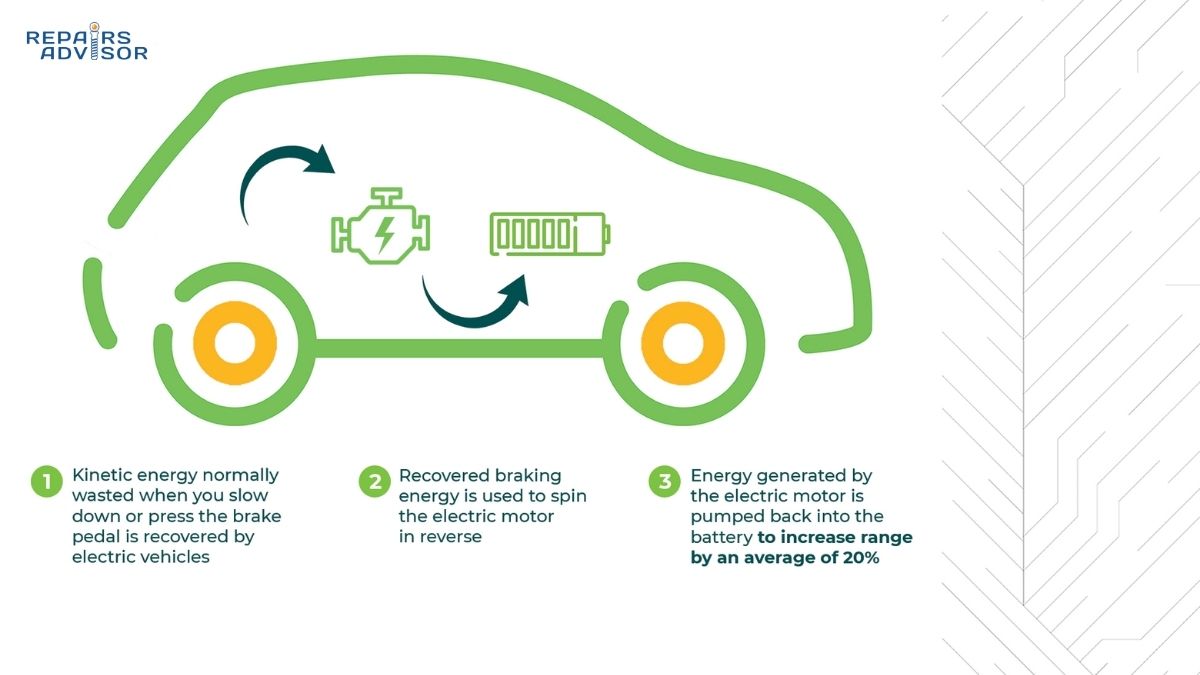
For intermediate-level enthusiasts building their understanding of EV architecture, the IMD sits at the intersection of regenerative braking systems, HV battery management, and vehicle safety electronics — learning how it works builds useful mental models for understanding why EVs behave differently from ICE vehicles during diagnostics. For professional technicians, the IMD data combined with structured sectioning and post-repair validation is the gold standard workflow for isolation-related complaints, and the relevant OEM service manuals contain the platform-specific calibration values and initialization sequences that general principles alone cannot provide.
Isolation Monitoring Device FAQ: Your Questions Answered
Isolation monitoring devices sit at the heart of electric and hybrid vehicle safety, yet most drivers have never heard of them until a warning light appears on the dashboard. Whether you’ve just seen an isolation fault code, want to understand how your EV protects you from its high-voltage system, or are preparing to work on HV vehicles professionally, the questions below cover the most common — and most important — things to know about IMD technology.
Quick Answer
An isolation monitoring device (IMD) is a safety component that continuously checks whether the high-voltage system in an EV or hybrid is properly isolated from the vehicle chassis. It detects insulation faults before they become a shock hazard. Common triggers include moisture intrusion, damaged HV cables, and battery pack contamination. Any isolation fault warning should be assessed by a certified high-voltage technician — this is not a system the driver can inspect or reset safely at home.
FAQs
What is an isolation monitoring device in an electric or hybrid vehicle?
An isolation monitoring device (IMD) is an active electronic safety module that permanently measures the insulation resistance between the vehicle’s high-voltage system and the chassis ground. In plain terms, it checks that the 400–800 volts flowing through the battery pack, cables, and motor stays within its intended circuit and doesn’t find a path to the car body where a person could contact it.
Unlike the physical insulation on HV cables — which is passive and silent — the IMD continuously reports a live resistance value to the battery management system. If that value drops below a safety threshold, it triggers warnings or protective actions. It’s one of several interlocking safety layers in the hybrid and EV battery system, operating alongside the HVIL and pyro-fuse to cover different failure scenarios.
How does an IMD actually measure insulation resistance?
The IMD injects a small, controlled test signal — typically a low-frequency AC or pulsed DC signal at very low current — onto the high-voltage bus. This signal is imperceptible to the vehicle’s power electronics during normal operation. The IMD then measures how much of that signal leaks from the HV rails through the insulation to the chassis ground (PE).
Using Ohm’s law (R = V ÷ I), the device calculates the effective insulation resistance in real time. High resistance means the insulation is intact. Falling resistance means insulation is degrading somewhere in the circuit. The IMD connects to both the positive and negative HV rails simultaneously, which allows it to detect both symmetrical faults (both rails degrading equally) and asymmetrical faults (only one rail affected) — a requirement of IEC 61557-8.
What resistance values are normal, and at what point does the IMD trigger a warning?
A healthy high-voltage system typically shows insulation resistance values well above 1 MΩ (megohm). As a general benchmark, most OEM calibrations follow a threshold expressed in Ω/V — meaning the minimum acceptable resistance scales with the system voltage.
At the warning threshold (approximately 500 Ω/V), the vehicle activates a dashboard alert but may allow continued operation. On a 400V system, this corresponds to roughly 200 kΩ. At the critical/shutdown threshold (lower, varies by OEM platform), the BMS may restrict power output or command the HV contactors to open, de-energizing the system entirely. Exact threshold values differ between manufacturers and are specified in OEM service documentation rather than published as universal standards.
What are the most common causes of isolation faults?
Moisture is the leading cause. Water intrusion into HV connectors, battery enclosures, or cable routing channels reduces insulation resistance — sometimes intermittently, appearing when the vehicle is cold or wet and clearing as it warms up. Physical cable damage is the second most common cause: HV wiring harnesses can chafe against chassis components over time, particularly in high-vibration areas near the motor or suspension.
Other causes include conductive contamination inside connectors (dirt, corrosion, metallic debris), electrolyte leakage from a damaged battery cell reaching the pack enclosure, and coolant leaks near HV components from the battery thermal management system. In integrated HV architectures, parasitic capacitance from long shielded cables or EMI suppression components can occasionally produce readings that resemble low-resistance faults, requiring careful interpretation during diagnosis.
What does fault code P0AA6 mean?
P0AA6 — “High Voltage System Isolation Fault” — is the primary DTC associated with isolation monitoring across most EV and hybrid platforms. It indicates the IMD has measured insulation resistance below the calibrated warning or alarm threshold. In some battery management systems (such as certain aftermarket BMS units), P0AA6 is informational only and does not restrict operation. In most OEM production vehicles, it triggers at minimum a driver warning and may invoke power limitation or HV shutdown depending on the severity level measured.
Retrieving P0AA6 is the starting point, not the end point. Always capture the full DTC list and freeze frame data at the same time — companion codes from the HVIL circuit, BMS, motor controller, or DC-DC converter often identify which subsystem is involved and can dramatically shorten diagnostic time.
Can I keep driving if my EV shows an isolation fault warning?
This depends on how severe the fault is and how your vehicle responds to it. Some OEM calibrations allow limited low-speed operation with an active warning to let the driver reach a safe location; others command an immediate HV shutdown. In any case, driving with an active isolation fault is not advisable beyond what’s needed to reach a safe place and stop.
The more important point: do not attempt to clear the code and continue as though nothing happened. An isolation fault means the electrical barrier between the HV system and the car body has measurably degraded. Even if the vehicle appears to drive normally, the protection margin against shock has been reduced. Have it inspected by a certified high-voltage technician promptly.
What’s the difference between the IMD and the HVIL system?
They protect against different failure modes, which is why both are needed. The IMD detects insulation degradation — a gradual, invisible process where the resistance between HV conductors and the chassis decreases over time due to moisture, heat, or physical damage. It works by active electrical measurement and catches problems that have no mechanical symptoms.
The high voltage interlock loop (HVIL) monitors whether HV connectors are physically latched and complete. The moment an HV connector is opened — during a service procedure, after a collision, or due to a latching failure — the HVIL circuit breaks instantaneously and disables HV operation. An HVIL fault can occur in a system with perfect insulation; an IMD fault can occur in a system where all connectors are properly seated. The two systems are complementary layers, not alternatives to each other.
Why do 800V EV architectures present new challenges for isolation monitoring?
Several factors combine to make IMD design harder as system voltage increases. Higher voltage increases the stress placed on insulation materials and raises the potential severity of any given fault, so the acceptable leakage current for a given safety margin is proportionally smaller. At the same time, 800V systems tend to have lower total system capacitance compared to 400V systems — which changes how the IMD test signal behaves and how parasitic capacitance from EMI suppression components affects measurements.
The existing primary standard, IEC 61557-8:2014, was developed predominantly around 400V architectures. Its threshold values and test methodologies don’t map cleanly to 800V systems, and industry working groups are still developing revised specifications. This means 800V platforms in production today are operating against OEM-derived safety cases rather than fully harmonised international standards — an area to watch as EV platforms from Tesla and others push higher-voltage designs into volume production.
How do technicians locate an isolation fault once it’s been detected?
The IMD measures aggregate insulation resistance across the entire HV circuit — it knows a fault exists but not where. Finding the location requires systematic sectioning: a certified HV technician disconnects HV subsystems one at a time while monitoring the IMD reading (or performing static megohmmeter tests after full de-energisation) to identify which subsystem’s removal restores normal resistance.
The typical sequence isolates external charging connections first, then the DC fast charging circuitry, then the traction inverter and traction motor, and finally the battery pack. The subsystem whose disconnection clears the fault is the fault zone. After any repair involving HV cable movement, a full post-repair isolation test is mandatory before HV reactivation — OEM procedures for platforms such as Toyota and Nissan specify the exact acceptance criteria and initialization sequence.
Is isolation monitoring required by law or industry standards?
Yes. Isolation monitoring is mandated by international standards applicable to all production EVs and hybrids. IEC 61557-8:2014 defines the technical requirements for IMD design and performance — minimum measurement accuracy, response time, and mandatory detection of both symmetrical and asymmetrical insulation faults. ISO 6469-3 covers EV-specific electrical safety, requiring that vehicles warn occupants when insulation resistance falls below specified thresholds and take protective action at critical levels.
Regional regulations in major markets — including FMVSS in the US and ECE standards in Europe — incorporate these or equivalent requirements. Every production EV and hybrid sold in regulated markets must include functioning isolation monitoring as a homologation requirement, not a manufacturer option.
What role does the IMD play during DC fast charging?
During a DC fast charging session, the IMD’s function becomes directly relevant to the charging protocol itself. Before high-current power transfer begins, the charging communication handshake — as defined in the CCS (Combined Charging System) standard — includes an insulation resistance check sequence. Charging will not proceed to full power delivery if the IMD reports a fault condition. This is one reason an active isolation fault will often prevent DC fast charging from initiating entirely, rather than simply triggering a dashboard warning. For a full breakdown of how that power negotiation works, see how DC fast charging control operates.
Can moisture cause an isolation fault that clears on its own?
Yes, and this is one of the more common diagnostic challenges in real-world EV service. Water intrusion into a connector or cable routing area can temporarily lower insulation resistance enough to trigger P0AA6, then evaporate as the vehicle warms up — leaving no trace during a subsequent inspection. The fault may return after rain, a car wash, or in cold morning conditions when condensation is present.
This intermittent pattern is a diagnostic clue rather than reassurance. It points strongly toward moisture as the root cause and toward a specific entry point — typically a compromised connector seal, a damaged cable grommet, or a battery enclosure seal that has deteriorated. The appropriate response is to inspect the HV circuit for moisture entry points while the fault history is still active in the BMS, not to wait for the fault to recur. Left unaddressed, moisture-related isolation issues tend to worsen over time as seals continue to degrade and repeated wetting accelerates corrosion of HV connector terminals.