The electric vehicle drivetrain has undergone one of the most significant packaging revolutions in automotive history. Where a conventional powertrain strings together an engine, transmission, driveshaft, differential, and axle across the length of the vehicle, the e-axle collapses much of that complexity into a single compact module sitting directly at the driven wheel. Understanding how e-axle integration works — how three distinct subsystems share a housing, a cooling circuit, and a control architecture — is essential knowledge for anyone working on or around modern electrified vehicles.
Quick Answer
An e-axle integrates three core components — an electric motor, a power electronics inverter, and a reduction gearbox — into one compact unit mounted directly at the vehicle’s driven axle. This eliminates the need for a central engine, long driveshafts, and a separate transmission, reducing weight by up to 40% compared to equivalent separate components. E-axles achieve system efficiencies above 90% and enable AWD configurations without a mechanical transfer case, simply by adding a second independent unit to the opposite axle.
What Is an e-Axle?
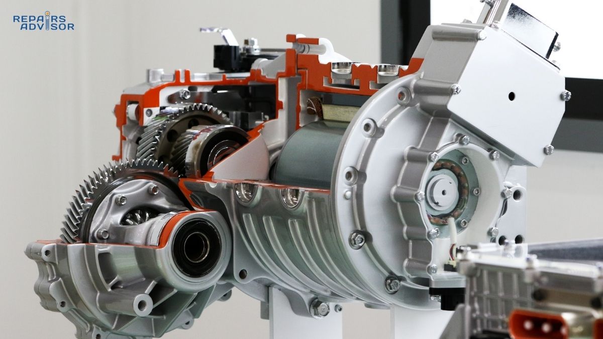
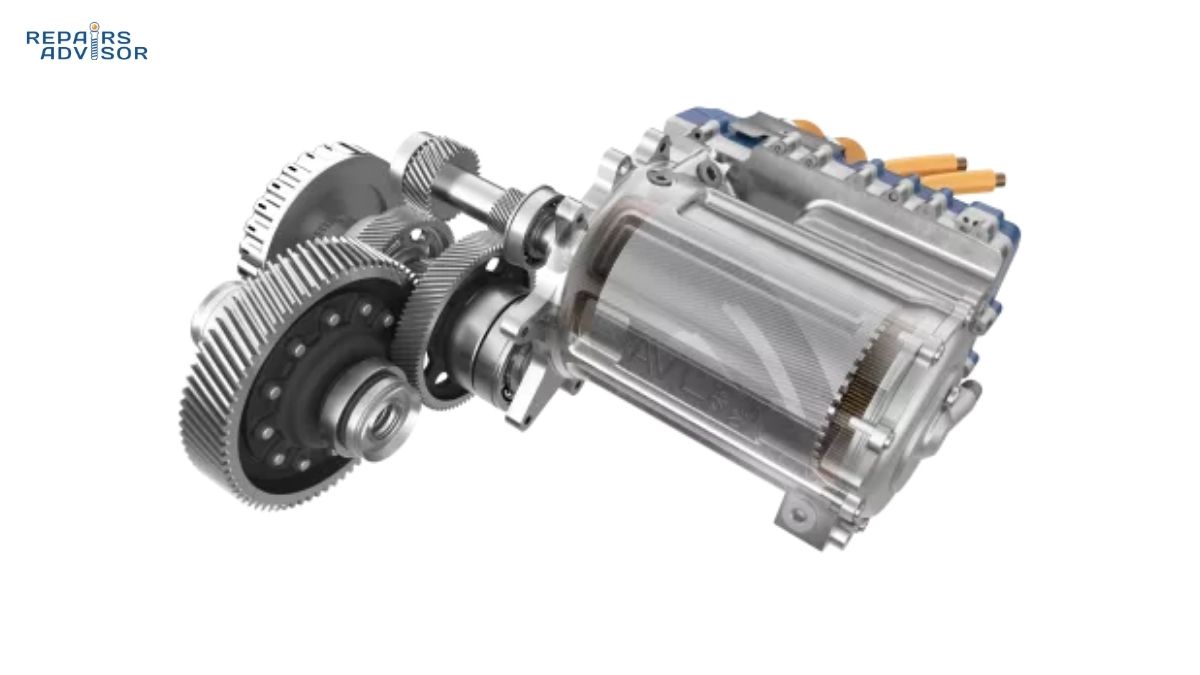
An e-axle — sometimes called an Electric Drive Unit (EDU) — is a powertrain module that integrates the electric motor, inverter, and reduction gearbox into a single shared aluminium housing. The assembly bolts to the vehicle’s suspension subframe, connects to half shafts at each end, and communicates with the vehicle control unit via a high-speed data bus.
The distinction between an e-axle and a generic EDU is worth a brief note. An EDU is the broader term for any integrated electric drive package. An e-axle specifically refers to an EDU that is axle-mounted, meaning the entire assembly sits at the driven axle rather than at a central chassis position. This shortens the power path from motor to wheels, reducing driveline losses and improving packaging efficiency.
How It Differs from a Conventional Drivetrain
In a traditional ICE vehicle, power flows from the engine through a clutch or torque converter, through a multi-speed transmission, down a propeller shaft in RWD or 4WD layouts, through a differential, and finally out through axle shafts to the wheels. That’s five or six major assemblies, each adding weight, mechanical losses, and potential failure points.
An e-axle removes the engine, the clutch, and in most cases the long propeller shaft entirely. The motor, inverter, and single-speed gearbox form one unit. The differential is integrated into the gearbox output. The drivetrain becomes fundamentally simpler and significantly lighter. To understand why these three subsystems are combined, it helps to look at what each one does — starting with the traction motor at the heart of the system.
Three Motor Placement Architectures
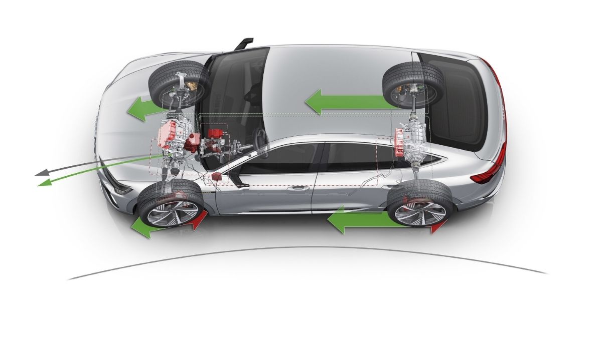
Before the e-axle became the dominant design, EVs used several drivetrain layouts. A central motor with a conventional driveshaft and differential was familiar but inherited ICE packaging compromises. A central motor with a separate in-axle gearbox was a step toward integration. The full e-axle — integrating everything directly at the axle housing — has largely won out for passenger car and commercial EV design. It frees up the central tunnel for additional battery capacity, lowers the vehicle’s centre of gravity, and eliminates the propeller shaft as a source of mechanical loss and packaging constraint.
The architecture’s flexibility extends further: pairing a front e-axle with a rear e-axle creates AWD without any mechanical link between the axles. No transfer case. No centre differential. Power split is managed electronically, which is why AWD electric vehicles can redistribute torque between front and rear axles in milliseconds — something a mechanical centre differential simply cannot match.
The Three Integrated Subsystems
The engineering challenge of e-axle integration isn’t just physically combining motor, inverter, and gearbox into one housing. It’s making them share thermal resources, lubrication paths, and structural loads simultaneously. Each subsystem has distinct requirements that must be resolved at the integration level.
The Electric Motor
The dominant motor type in modern e-axles is the Permanent Magnet Synchronous Motor (PMSM). PMSM designs offer the best combination of torque density, efficiency (typically 92–96% at optimal operating points), and controllability. The motor consists of a stator with three-phase windings on a laminated iron core, and a rotor carrying rare-earth permanent magnets — typically neodymium-iron-boron composites.
Operating speeds in e-axle applications typically reach 10,000–35,000 RPM. At those speeds, the motor produces rated torque, but rotational speed must be stepped down significantly before it reaches the wheels — normal wheel speed is 500–1,500 RPM. That speed reduction is the gearbox subsystem’s job.
One key evolution in e-axle motor design is the shift from water-jacket cooling to oil cooling. In integrated e-axles, motor oil can be shared with the gearbox lubricant, circulated directly through stator windings or rotor channels, and managed within a single thermal loop. This eliminates the separate water cooling jacket required in standalone motors, simplifies sealing at the motor-gearbox interface, and improves thermal performance under sustained high-load conditions.
The Inverter (Power Electronics)
The inverter converts DC power from the high-voltage battery pack into three-phase AC for the motor, and manages all aspects of motor control — speed, torque, direction, and regenerative energy recovery. It’s also the subsystem most sensitive to heat, and in the integrated e-axle package it faces the most severe packaging constraints of the three.
Modern e-axle inverters increasingly use Silicon Carbide (SiC) semiconductor switches rather than traditional Insulated Gate Bipolar Transistors (IGBTs). SiC operates at higher switching frequencies with lower switching losses and reduced heat generation — particularly valuable in an integrated package where available cooling surface area is limited. At equivalent power levels, SiC inverters can be meaningfully smaller while maintaining efficiency.
The inverter also manages the transition between motoring and generating modes, which is central to regenerative braking. When the driver lifts off the throttle or applies the brakes, the inverter switches the motor into generator mode, converting kinetic energy back into DC current for the battery. This energy recovery is coordinated with brake-by-wire and ABS systems at the vehicle level. The motor controller and inverter electronics are among the most technically demanding components in the entire assembly.
System voltage matters significantly. 800V architecture — now standard on performance EVs and some commercial platforms — reduces current levels by half compared to 400V systems at equivalent power. Lower current means smaller conductor cross-sections, less heat generation, faster DC charging, and better e-axle efficiency overall.
The Reduction Gearbox
Unlike ICE transmissions with 6–10 forward gears, the e-axle gearbox is almost universally a single-speed fixed reducer. Electric motors produce usable torque across a far wider RPM range than combustion engines, so multi-ratio shifting isn’t needed for performance. The gearbox’s job is to reduce motor speed to wheel speed — typically at a fixed ratio between 8:1 and 12:1 — while multiplying torque proportionally.
Two-speed variants are emerging for commercial vehicles and performance applications. Research has shown that a second gear can improve motorway-cycle motor efficiency by 5–7% without increasing urban energy consumption, as the motor operates in a higher-efficiency region at highway speeds. But the added complexity and cost still limits two-speed designs to specialised applications.
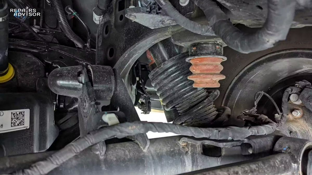
Within the e-axle, the differential is integrated alongside the reduction gearing. Its function is unchanged from ICE drivetrains — it allows driven wheels to rotate at different speeds when cornering — but in the e-axle it shares the same oil sump, housing, and bearing preloads as the rest of the gearbox. Output shafts connect to the wheel-end half shafts in the conventional manner, though the CV joints connecting them to the wheel hubs see higher peak torque loads due to the e-axle’s instant torque delivery.
Shared Housing Design
The single aluminium casting that houses motor, inverter, and gearbox is the physical foundation of the integration. Cast aluminium provides the structural rigidity needed to manage motor reaction torque during hard acceleration while keeping the assembly light enough to deliver the weight savings the e-axle concept promises.
The housing also routes coolant passages and oil galleries between subsystems. Shared oil circuits allow a single fluid to lubricate the gearbox and differential, cool the motor, and serve as the thermal coupling medium between components. This reduces external plumbing, sealing complexity, and the number of fluid service points. Compared to separate equivalent components, well-optimised integrated e-axle assemblies achieve up to 40% mass reduction — a meaningful contribution to vehicle range and handling dynamics.
Integration Engineering Challenges
Combining three thermally active, mechanically loaded subsystems into one compact envelope creates engineering problems that don’t arise when each component is designed independently. The three areas demanding the most integration attention are thermal management, mechanical packaging within the vehicle’s suspension architecture, and electronic coordination.
Thermal Management
High-power motors and gearboxes generate substantial heat under sustained load, and inverter semiconductors — especially at high switching frequencies — are thermally constrained even under moderate conditions. In a standalone installation, each component can be sized and cooled independently. In an integrated e-axle, all heat sources compete for the same cooling resources in the same compact envelope.
Two primary approaches are used in production e-axles. Passive cooling — using phase-change materials embedded in heat sinks — can reduce peak motor temperatures by 12–15°C without additional energy consumption, but is insufficient for sustained high-power operation. Active cooling using a water-glycol coolant circuit is standard on passenger and commercial e-axles; the loop connects to the vehicle’s central thermal management system, which also handles high-voltage battery cooling and heating.
The most thermally effective current approach is oil-water hybrid cooling: motor oil handles lubrication and primary cooling of the motor and gearbox, while a separate water-glycol circuit manages the inverter. This approach restricts motor-gearbox temperature variation to approximately ±3°C and improves heat transfer efficiency by around 25% compared to water-only designs. In practical terms, sudden power derating during sustained highway driving is almost always a thermal protection response — the e-axle controller reducing torque output to prevent overheating — not an underlying fault. Checking coolant level and flow rate is the correct first diagnostic step.
Packaging and Suspension Integration
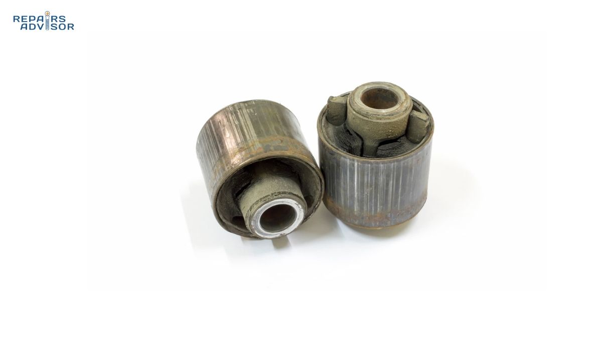
Mounting a dense e-axle assembly at the driven axle increases unsprung mass — the portion of vehicle mass that moves with the wheels over road irregularities rather than being isolated by the suspension. Higher unsprung mass degrades ride quality and wheel control. E-axle designers address this through compact high-pole-count motor topologies and optimised housing geometry, though the tradeoff is never fully eliminated.
On heavy commercial vehicles with air suspension, packaging challenges are compounded: airbag assemblies occupy much of the space behind the axle housing, competing with e-axle cooling and mounting needs. Commercial e-axle integrations for Class 7–8 trucks typically require purpose-designed suspension mounting interfaces and dedicated cooling routing that differs substantially from the original ICE chassis.
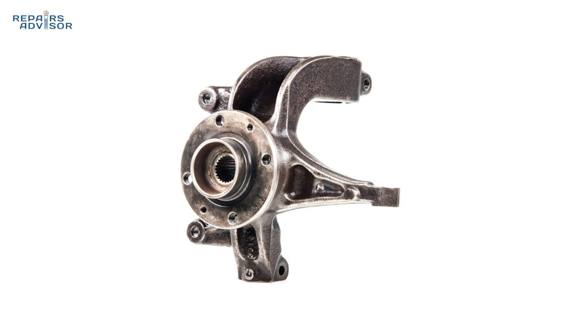
The axle housing itself takes on a more complex structural role with e-axle integration: it manages motor reaction torque, supports cooling and suspension interfaces, and carries high-voltage electrical connections. The wheel bearing assemblies at each end see higher dynamic loads than their ICE equivalents, because instant electric torque delivery creates sharper transients than combustion acceleration can produce.
Electronic Integration
The e-axle communicates continuously with the Vehicle Control Unit (VCU) via CAN bus or Automotive Ethernet, exchanging torque commands, speed data, thermal status, and fault information. In dual-axle AWD configurations, two independent e-axle control units work with the VCU and stability systems to execute torque vectoring in real time.
Effective torque vectoring requires the electronic stability control system to share yaw rate, lateral acceleration, and wheel speed data with the e-axle controllers at update rates fast enough to influence individual wheel torque within a single vehicle dynamics event — typically demanding control loop latencies below 10 milliseconds. This tight closed-loop integration is what distinguishes sophisticated electric AWD systems from simpler dual-motor configurations.
Regenerative braking coordination adds another layer. When the driver brakes, the brake controller must blend hydraulic caliper pressure with regenerative torque from the e-axle motor in a way that feels consistent and predictable. This blending is managed cooperatively between the e-axle controller, the brake-by-wire actuator, and the VCU. Miscoordination between these systems is one of the more common sources of inconsistent pedal feel on production EVs.
Torque Vectoring and Performance Advantages
One of the most significant performance benefits of the e-axle architecture is how naturally torque vectoring emerges from it. In a conventional AWD drivetrain, vectoring torque between axles requires an active transfer case with multi-plate clutches and a complex hydraulic control system — mechanically expensive and limited in response speed. In an e-axle AWD system, front-to-rear torque vectoring is essentially a software function: the VCU adjusts the torque command to each e-axle independently. There’s no additional hardware cost beyond what’s already required for dual-motor AWD.
Single vs. Dual Motor per Axle
Placing two separate motors on a single axle — with independent inverter control — enables left-right torque vectoring without mechanical differential action. The Tesla Cybertruck tri-motor platform and Rivian R1T quad-motor configuration both use this approach on at least one axle, allowing per-wheel torque modulation that redirects traction to the highest-grip wheel in real time.
There is a trade-off. With two motors each driving one wheel, the maximum torque available to one wheel is limited to what that single motor can produce. A single-motor-plus-clutch approach can theoretically redirect 100% of total axle torque to one wheel, since the clutch transfers the full output of one large motor entirely to one side. Which approach is preferable depends on the performance priorities of the specific application. Most passenger car e-axles use a single motor with integrated differential for cost and simplicity.
Efficiency and Response
System efficiency above 90% is achievable in well-optimised e-axle designs using SiC inverters and precision-cut gear profiles — compared to overall drivetrain efficiency of 30–40% from fuel energy to wheel power in a typical ICE vehicle. The shorter power path from motor to wheel, with no propeller shaft, no torque converter, and no multi-stage gear changes, reduces mechanical losses at every step.
Torque response is also qualitatively different. An e-axle can reach full rated torque in under 100 milliseconds from standstill — faster than any driver can detect. This instant delivery is what produces the characteristic linear acceleration of electric vehicles, and it’s also why traction control calibration and stability control integration are so important in high-performance e-axle applications.
Diagnostics and Service: What Technicians Need to Know
High-Voltage Safety: E-axle systems operate at 400–800V DC. Any physical access to e-axle components requires full high-voltage system de-energisation, insulation resistance verification (typically above 1 MΩ), and the use of appropriate Class 0 or Class 00 insulated PPE. This work is reserved for certified high-voltage technicians following OEM service procedures. The following is educational content for understanding system behaviour — not a DIY service guide.
For most technicians, the practical reality of e-axle service is that the assembly is a sealed module. OEM procedures typically define e-axle work at the replacement level: the unit is unbolted from its subframe mounts, half shafts are disconnected, high-voltage cables are disconnected following proper isolation procedures, and the assembly is exchanged. Subcomponent repair — individual inverter modules, motor bearings, or gearbox internals — is generally outside dealer and independent workshop scope, though specialist EV rebuilders do perform inverter-level repair in some cases.
The accessible service points on an installed e-axle are: coolant connections and cooling system maintenance, mounting hardware and subframe connections, half shaft and CV joint condition, high-voltage cable connections following de-energisation, and gearbox oil level where a separate service interval is specified. Understanding isolation monitoring device operation and the high-voltage interlock loop (HVIL) is fundamental before any physical contact with e-axle high-voltage connections.
Common Diagnostic Indicators
Unexpected power derating at sustained highway speeds is the most common e-axle symptom. This is almost always a thermal protection response — the e-axle controller reducing motor output to prevent overheating. Check coolant level and flow rate before suspecting an e-axle fault. Persistent derating at normal ambient temperatures warrants a scan tool session to retrieve thermal data from the e-axle control unit.
NVH complaints — particularly a gear whine that increases with vehicle speed rather than engine RPM — are characteristic of e-axle gear mesh frequency issues. The sound typically appears at a specific speed band and persists during coasting. Distinguishing e-axle gear noise from wheel bearing noise requires noting whether the sound changes under load or regenerative braking: gear mesh noise varies with torque loading; wheel bearing noise typically does not.
Loss of regenerative braking — where the vehicle coasts freely when lifting off the throttle instead of decelerating — may indicate an inverter fault, a high-voltage communication fault, or a protective software shutdown. Stored DTCs relating to the e-axle control module or HV contactor circuit will typically be present. Vibration on hard acceleration, particularly in cold conditions, may point to CV joint wear — the high peak torque output of the e-axle places significant stress on half shaft joints, accelerating wear where lubrication is compromised or boots have failed.
The Road Ahead for e-Axle Technology
The e-axle is not a transitional technology — it is the established architecture for electrified drivetrains in both passenger cars and commercial vehicles. Ongoing development focuses on three areas: higher voltage systems (800V and beyond) to reduce inverter current and thermal loads; two-speed gearbox refinement to extend motor efficiency at highway speeds; and tighter integration with battery pack and cabin HVAC thermal management to maximise whole-vehicle energy efficiency.
For workshops, the trend toward sealed e-axle module replacement creates new service requirements. Traditional drivetrain skills — bearing replacement, gearbox rebuilding, differential setup — apply less directly to a unit designed for exchange. But understanding how e-axle integration works, its thermal behaviour, its electronic interfaces, and its high-voltage safety requirements, positions technicians to diagnose and manage EV drivetrains confidently as the vehicle parc continues to shift.
For anyone seeking to work on or understand an e-axle-equipped vehicle, the manufacturer’s service documentation is the essential starting point. The car repair manuals available for modern EVs and hybrids include e-axle diagnostic procedures, fluid service intervals, and high-voltage safety protocols specific to each model. Given the safety-critical nature of high-voltage drivetrain work, professional consultation is strongly recommended for anything beyond inspection and fluid-level checks on e-axle-equipped vehicles.