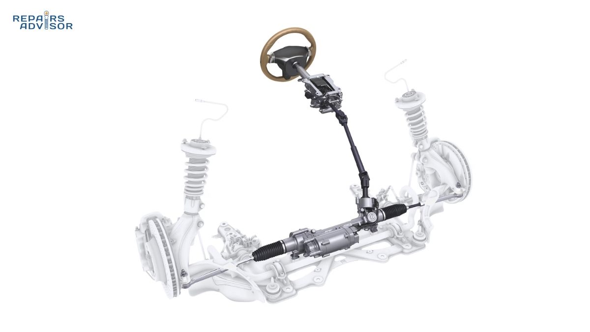
Modern vehicles have replaced traditional hydraulic power steering with sophisticated electronic power steering (EPS) control systems that represent one of the most advanced automotive technologies in use today. The EPS control system is the intelligent electronic brain that manages every aspect of electric steering assistance, from processing sensor inputs to controlling powerful electric motors with millisecond precision.
Unlike hydraulic systems that provide constant assistance regardless of driving conditions, EPS control systems adapt steering effort dynamically based on vehicle speed, driver input, and road conditions. At parking lot speeds, the system provides maximum assistance for effortless maneuvering. On the highway, it reduces assistance to deliver stable, confident steering feel. This intelligence comes from sophisticated control algorithms, multiple sensor inputs, and real-time processing capabilities that rival modern computers.
The importance of EPS control systems extends far beyond steering assistance. These systems form the foundation for advanced driver assistance systems (ADAS) including lane departure warning and adaptive cruise control. They enable features like automatic parking, lane centering, and even semi-autonomous driving capabilities. The EPS control system continuously monitors itself for faults, implements multiple layers of safety protection, and maintains manual steering capability even during complete electronic failure.
Understanding how these systems work is essential whether you’re an intermediate DIY enthusiast troubleshooting steering issues, a professional mechanic diagnosing complex electrical faults, or simply curious about the technology controlling your vehicle. This comprehensive guide explores the electronic architecture, sensor technologies, motor control strategies, safety systems, and diagnostic approaches that make modern steering both effortless and remarkably intelligent.
For Beginners: Think of the EPS control system as a smart assistant for your steering. When you turn the wheel, sensors detect how much effort you’re applying and how fast you’re driving. The control system’s computer (ECU) processes this information and tells an electric motor exactly how much help to provide. It’s like having an invisible helper that knows when you need more or less assistance, making parking easy while keeping highway driving stable and controlled.
Core EPS Control System Architecture
The EPS control system operates as an integrated electronic network combining sensors, processors, and actuators into a cohesive steering management system. At its core lies the Electronic Control Unit (ECU), a specialized automotive computer designed specifically for the demanding requirements of steering control.
Electronic Control Unit (ECU) Components
The EPS ECU represents the decision-making center of the entire system, housed in a robust enclosure designed to withstand automotive environmental extremes including temperature fluctuations, vibration, and electromagnetic interference. Modern EPS ECUs utilize powerful microcontrollers from families like NXP’s S32K series or STMicroelectronics’ STM32G0, typically featuring 32-bit ARM Cortex processors running at 80-120 MHz. These microcontrollers provide sufficient computational power for real-time control algorithms while maintaining automotive-grade reliability.
The ECU architecture includes multiple functional blocks working in coordination. Input processing circuits condition signals from various sensors, converting analog voltages and digital pulse trains into data the microcontroller can process. These circuits include operational amplifiers, analog-to-digital converters (ADCs) running at 10-12 bit resolution, and signal filtering to remove electrical noise. The microcontroller samples these inputs continuously, typically at rates of 1-2 kHz for critical sensors like the torque sensor, ensuring no steering input goes undetected.
Output drivers form another critical component, generating the pulse-width modulation (PWM) signals that control the electric motor. These drivers must switch high currents rapidly (10-20 kHz PWM frequency) while minimizing electromagnetic emissions that could interfere with other vehicle electronics. Modern EPS systems implement sophisticated gate driver ICs specifically designed for three-phase motor control, capable of handling 50-150 amps peak current depending on motor size.
Safety circuits permeate the ECU design. A watchdog timer continuously monitors the microcontroller, resetting the system if software execution stalls. Redundant power supplies ensure the ECU remains functional even with supply voltage fluctuations. Temperature monitoring protects against thermal damage, and built-in self-test routines verify critical functions during each ignition cycle. This multi-layered safety approach aligns with ISO 26262 functional safety standards, typically achieving ASIL-D classification for steering systems.
The ECU also integrates a CAN (Controller Area Network) transceiver, enabling communication with other vehicle systems over the standardized automotive network. More details on how ECUs process automotive data can be found in our guide on how ECUs work.
Controller Area Network (CAN) Integration
Modern EPS systems don’t operate in isolation—they form integral nodes on the vehicle’s CAN bus network, communicating with multiple electronic control units simultaneously. The CAN bus implementation follows ISO 11898 standards, typically operating at high-speed rates of 500 kilobits per second for time-critical steering data. This message-based serial network allows the EPS ECU to share information efficiently without requiring dedicated point-to-point wiring to every system.
The EPS control system both receives and transmits critical data over the CAN network. Incoming messages provide essential inputs for steering control algorithms. Wheel speed data from the ABS module enables speed-dependent steering characteristics. Engine status information allows the system to compensate for engine vibration and torque fluctuations. Vehicle stability data from the electronic stability control system enables enhanced safety interventions during skids or loss of control situations.
Outgoing CAN messages broadcast steering position and torque data to systems that require this information. ADAS systems consume steering angle data for lane keeping algorithms. The instrument cluster displays steering-related warnings when faults occur. The body control module may disable certain features if steering system faults are detected. This bidirectional data exchange creates a coordinated vehicle control system where steering integrates seamlessly with braking, traction control, and advanced safety features.
The CAN protocol’s arbitration mechanism ensures critical steering messages receive priority during network congestion. Message identifiers are carefully assigned so that urgent steering data preempts less time-critical information like climate control settings. The system monitors CAN communication integrity continuously, detecting lost messages, bit errors, and communication failures that could compromise steering control. If CAN communication is lost, the EPS system enters a fail-safe mode that relies solely on direct sensor inputs while maintaining basic steering assistance.
Professional Insight: Advanced EPS implementations utilize CAN FD (Flexible Data-rate) protocol extensions in newer vehicles, increasing data throughput to 5 Mbps for bandwidth-intensive ADAS features. The higher speed enables transmission of detailed sensor fusion data and supports future steer-by-wire architectures where mechanical backup systems may be eliminated.
Sensor Input Systems
EPS control systems rely on multiple sensors to understand driver intent, vehicle conditions, and steering system status. These sensors provide the raw data that control algorithms process to deliver appropriate steering assistance. The accuracy, reliability, and redundancy of these sensor systems directly determine steering quality and safety.
Torque Sensor Technology and Operation
The torque sensor stands as the most critical input for EPS control, measuring the rotational force the driver applies to the steering wheel. This sensor enables the system to distinguish between gentle corrections and aggressive steering inputs, scaling assistance appropriately. The measurement principle relies on a calibrated torsion bar—a specially designed shaft section that twists measurably under torque load while remaining well within elastic limits.
The torsion bar connects the steering wheel input shaft to the pinion output shaft, with the sensor positioned to detect the angular displacement between these shafts. When the driver turns the wheel, input torque causes the torsion bar to twist slightly, typically just 4-5 degrees at maximum rated torque. This small angular deflection is measured by various sensor technologies, each with distinct advantages.
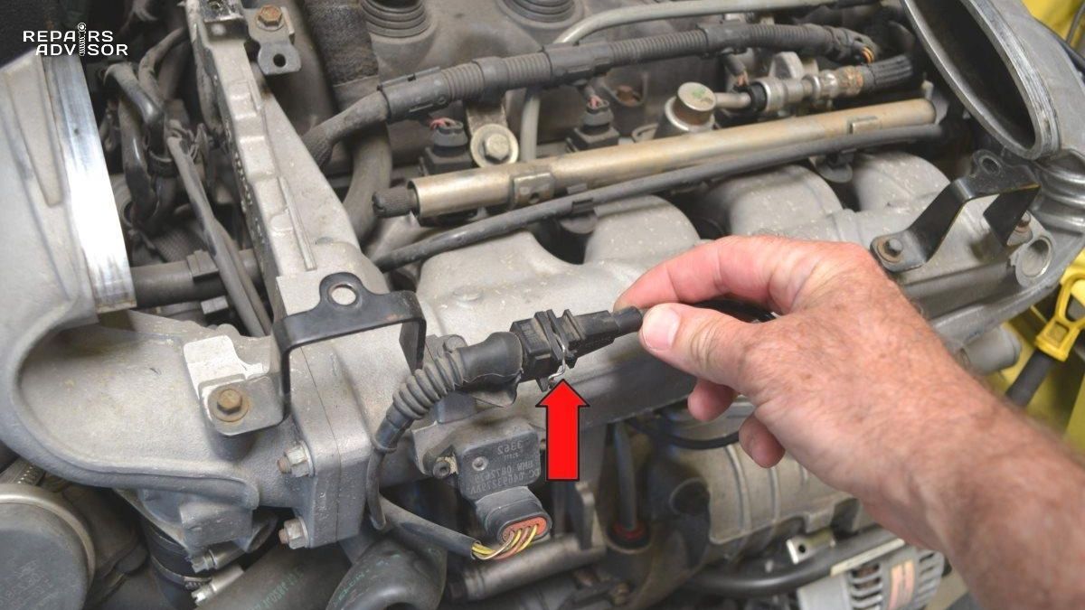
Hall effect torque sensors dominate mass-market applications due to their proven reliability and moderate cost. These sensors use magnetic field changes to detect torsion bar twist. A magnet ring attaches to the input shaft while a Hall sensor array mounts to the output shaft. As the torsion bar twists, the magnetic field orientation changes relative to the Hall sensors, producing proportional voltage changes. Modern implementations use dual inverse signal architecture—two separate sensor channels that move in opposite directions. When one signal voltage increases from 2.5V toward 4.75V during right turn, the complementary signal decreases toward 0.25V. This inverse relationship enables the ECU to detect sensor faults immediately; signals that move together indicate a malfunction.
Magnetoresistive sensors appear in premium vehicles from manufacturers like Volkswagen, Audi, BMW, and Volvo. These sensors measure resistance changes in thin-film elements exposed to magnetic fields from the torsion bar assembly. Magnetoresistive technology delivers higher sensitivity than Hall effect sensors, enabling detection of smaller torque changes with better signal-to-noise ratios. The more compact sensor design facilitates packaging in tight engine compartments, though higher manufacturing costs limit adoption to upscale models. Systems from Bosch and ZF frequently incorporate magnetoresistive sensing for superior steering precision.
Inductive torque sensors target budget-segment vehicles where cost constraints dominate design decisions. These sensors detect electromagnetic field changes as the torsion bar rotates relative to sensor coils. While offering lower resolution than magnetoresistive designs, inductive sensors provide exceptional robustness against vibration, temperature extremes, and electromagnetic interference from other vehicle systems. The simpler construction and proven reliability make them suitable for entry-level vehicles where steering precision requirements are less demanding.
Signal processing converts raw sensor voltages into torque values the ECU can use. The typical measurement range spans ±5 to ±8 Newton-meters (Nm), covering everything from gentle lane changes to maximum steering effort during parking. Resolution reaches 0.01 Nm in modern systems, enabling smooth control even with tiny steering inputs. The ECU samples torque sensor signals at 1-2 kHz, ensuring the system responds to driver inputs with minimal lag—typically under 50 milliseconds from input to motor response.
Steering Angle Sensor (SAS) Implementation
The steering angle sensor ranks as arguably the most vital component in modern EPS systems, explaining why redundant measurement channels are standard practice. This sensor determines absolute steering wheel position through multiple complete rotations, typically measuring ±540 degrees (three full turns lock-to-lock). The sensor must maintain position knowledge even when the vehicle is off, requiring non-volatile encoding methods that don’t depend on continuous power.
Optical encoder technology dominates steering angle sensing due to its high resolution and reliability. The sensor contains a code wheel—a transparent disc with precisely printed patterns of opaque and transparent segments arranged in multiple concentric tracks. An LED illuminates one side of the disc while photodiode arrays detect light passing through the transparent segments on the opposite side. Each track uses a different encoding pattern, with multiple tracks combined to create a unique position code for every possible steering angle.
The multi-track design enables absolute position determination through clever encoding schemes. A common implementation uses Gray code on inner tracks for fine position resolution (typically 0.1-0.5 degree accuracy) combined with coarser encoding on outer tracks for revolution counting. When the ignition powers on, the ECU reads all track patterns simultaneously, calculating both the steering angle within the current rotation and which rotation (1st, 2nd, or 3rd) the wheel occupies. This eliminates initialization procedures—the sensor always knows its position.
Beyond position measurement, the steering angle sensor calculates steering wheel velocity—the rate of rotation. The ECU differentiates successive position measurements to determine angular velocity in degrees per second. This velocity data enables advanced control features including predictive steering assistance and stability interventions. During rapid steering inputs (panic maneuvers), velocity information helps the system distinguish emergency situations from normal driving, triggering appropriate responses. More details about steering angle sensor operation are available in our comprehensive guide on how steering angle sensors work.
The sensor’s criticality extends beyond steering assistance. Electronic stability control and traction control systems depend on accurate steering angle data to determine driver intent. Lane departure warning, lane keeping assist, and automatic emergency steering all consume steering angle information. Incorrect sensor calibration can cause these systems to misinterpret driver actions, potentially triggering false interventions or failing to activate when needed.
Calibration requirements make steering angle sensors particularly demanding for service. The sensor must learn its center position after any steering component replacement, wheel alignment, or even a simple battery disconnect on some vehicles. Professional scan tools perform this calibration by commanding the steering to full lock in both directions while learning the center position. Attempting repairs without proper recalibration can result in steering system faults, disabled safety systems, and dangerous handling characteristics.
Safety Warning: ⚠️ Professional Calibration Required: Steering angle sensor calibration must be performed after any suspension, steering, or wheel alignment work. Incorrect calibration can cause dangerous ADAS malfunctions and stability control issues. Never assume the sensor will self-calibrate—improper calibration compromises vehicle safety systems that rely on accurate steering position data.
Vehicle Speed Input and Processing
Vehicle speed forms the third critical input for EPS control algorithms, enabling the speed-dependent steering characteristics that make modern EPS systems feel natural across all driving conditions. The EPS ECU doesn’t measure speed directly; instead, it receives vehicle speed data through the CAN bus network from other vehicle systems already equipped with speed sensing capability.
Primary speed data originates from wheel speed sensors integrated into the ABS system. These sensors, detailed in our article on how wheel speed sensors work, monitor individual wheel rotation rates. The ABS module calculates vehicle speed from wheel sensor data and broadcasts this information on the CAN network where the EPS ECU can access it. This approach eliminates redundant speed sensors while ensuring multiple systems use consistent speed values.
Some vehicles supplement wheel speed data with transmission output shaft speed sensors or GPS-based speed calculations in ADAS-equipped models. The transmission speed sensor provides particularly reliable data during low-speed maneuvering when wheel slippage might affect wheel speed sensor accuracy. GPS speed data offers validation for highway driving, though its lower update rate (typically 1-10 Hz) makes it unsuitable as the primary speed input for responsive steering control.
The EPS control algorithm applies speed-dependent modifications to steering assistance based on vehicle velocity. At very low speeds (0-10 mph), maximum motor assistance creates effortless parking maneuvers. As speed increases through city driving ranges (10-40 mph), assistance reduces progressively, providing more resistance and better road feedback. At highway speeds (50+ mph), minimal assistance ensures stable, predictable steering with enhanced straight-line tracking. This graduated response creates steering characteristics that feel intuitive and appropriately weighted regardless of driving conditions.
Advanced systems implement more sophisticated speed-dependent features. Damping control—the system’s resistance to rapid steering movements—increases with vehicle speed to reduce sensitivity to wind gusts and road imperfections. Return-to-center assistance strengthens at higher speeds, helping maintain straight tracking. Some premium systems vary not just assistance magnitude but also steering ratio characteristics, providing quicker response at low speeds for agile parking while delivering more progressive response at high speeds for stability.
For Beginners: The speed-dependent steering system works like an automatic adjustment that makes parking easy while keeping highway driving safe. When you’re going slowly in a parking lot, the electric motor provides lots of help so you can turn the wheel with one finger. When you’re driving fast on the highway, the system reduces assistance so the steering feels solid and stable. You never have to think about this—the computer adjusts automatically based on how fast you’re traveling.
Electric Motor Control Systems
The electric motor in an EPS system converts electrical energy into mechanical torque that assists the driver’s steering inputs. Modern EPS systems universally employ brushless DC (BLDC) motors for their superior efficiency, compact size, and maintenance-free operation. Understanding motor control requires examining both the motor’s physical construction and the sophisticated electronic drive strategies that make precise torque control possible.
Brushless DC (BLDC) Motor Fundamentals
BLDC motors dominate EPS applications because they offer the ideal combination of power density, efficiency, and controllability. A typical EPS motor measures just 10-15 cm in diameter yet delivers 400-1600 watts of mechanical power—enough to provide substantial steering assistance even in heavy vehicles. This compact packaging allows motor placement directly on the steering column, pinion gear, or rack and pinion assembly depending on system architecture.
The motor construction features a permanent magnet rotor—the rotating component with alternating north and south magnetic poles arranged circumferentially. Common configurations use 4, 6, or 8 magnetic pole pairs, with more poles generally enabling smoother operation. The rotor mounts on precision bearings allowing free rotation with minimal friction. Because the magnets are permanent, no electrical energy flows to the rotor, eliminating the brushes and commutator required by older brushed motor designs.
The stator—the stationary outer component—contains three electromagnetic coils wound around laminated steel cores. These coils, designated U, V, and W phases, are arranged 120 electrical degrees apart. When current flows through a coil, it creates a magnetic field that interacts with the permanent magnet rotor. By energizing the stator coils in sequence, the controller creates a rotating magnetic field that “drags” the rotor around. The elimination of mechanical brushes means zero brush wear, no arcing, reduced electromagnetic interference, and maintenance-free operation.
Power ratings vary based on vehicle weight and assistance requirements. Compact cars typically employ 400-800 watt motors providing modest assistance. Mid-size vehicles use 600-1000 watt motors for greater assistance capability. Large SUVs and trucks require 1000-1600 watt motors to deliver sufficient torque for effortless low-speed maneuvering. Some emerging systems utilize 48-volt electrical architectures instead of conventional 12-volt systems, enabling higher power output with reduced current draw and improved efficiency.
Motor Commutation and PWM Control Strategies
Controlling a BLDC motor requires precise timing of current flow through the three stator phases. Unlike brushed motors where mechanical commutators handle this automatically, BLDC motors rely on electronic commutation—the sequential switching of phase currents using power transistors. The EPS ECU generates these switching patterns based on rotor position, creating the rotating magnetic field that produces motor torque.
The power stage implementing this switching consists of six MOSFET transistors arranged in a three-phase bridge configuration. Each motor phase connects between a high-side transistor (linking to battery positive) and a low-side transistor (linking to ground). By selectively turning these transistors on and off, the controller directs current through the motor phases in carefully timed sequences. For detailed information about motor control electronics, see our article on how EPS motor + controller works.
The basic control strategy uses six-step trapezoidal commutation, where each electrical cycle divides into six distinct switching states. At any moment, current flows through two of the three phases while the third remains unpowered. For example, during one step, phase A might be driven positive, phase B driven negative, and phase C left floating. The next step rotates this pattern 60 electrical degrees, typically switching phase C positive, phase A negative, and phase B floating. This sequence continues through all six states, completing one electrical cycle. The number of electrical cycles per mechanical revolution depends on the rotor’s magnetic pole pairs—a motor with four pole pairs requires four electrical cycles per mechanical rotation.
Pulse-width modulation (PWM) provides precise speed and torque control within this commutation framework. Rather than applying constant voltage to the active phases, the controller rapidly switches the power on and off at frequencies between 10-20 kHz—well above human hearing range. The duty cycle (ratio of on-time to total cycle time) determines the effective voltage applied to the motor. A 25% duty cycle delivers quarter voltage, producing light assistance. A 75% duty cycle delivers three-quarter voltage for stronger assistance. The motor’s electrical inductance smooths these rapid pulses into relatively constant current, with the average current proportional to the duty cycle.
Advanced systems implement sinusoidal commutation using field-oriented control (FOC) or space vector modulation (SVM) techniques. These methods continuously vary the current in all three phases following sinusoidal patterns rather than the stepped trapezoidal approach. The result is exceptionally smooth motor operation with minimal torque ripple—the variation in output torque during rotation. Premium vehicles from luxury manufacturers frequently employ sinusoidal control, though the technique requires more computational power and sophisticated current sensing.
Position sensing enables proper commutation timing. Most EPS motors use Hall effect sensors—typically three sensors positioned 60 degrees apart—that detect rotor magnet positions. These sensors generate digital high/low signals based on magnetic polarity, with the combination of three sensor states indicating which commutation step should be active. Some advanced systems eliminate Hall sensors entirely, inferring rotor position from back-EMF (electromagnetic force) generated in the unpowered phase. This sensorless control reduces cost and complexity while maintaining performance for most applications.
Torque Assist Calculation and Control Algorithms
Converting sensor inputs into appropriate motor commands represents the EPS control system’s core intelligence. The assist calculation algorithm weighs multiple factors to determine how much motor torque should supplement the driver’s effort, creating steering feel that adapts seamlessly to driving conditions while maintaining safety and reliability.
The fundamental assist calculation starts with driver input torque from the torque sensor. The control algorithm applies this torque value to an assist curve—a mathematical relationship programmed into the ECU that maps input torque to motor assistance. At low input torques (gentle steering corrections), the system might provide 8:1 assistance, meaning the motor contributes eight times the driver’s effort. As input torque increases (harder steering), the assistance ratio typically decreases to prevent excessive total force. This nonlinear relationship prevents the steering from feeling overly sensitive during aggressive inputs while ensuring easy effort for normal driving.
Vehicle speed profoundly influences the assist curve. The controller actually maintains multiple assist curves optimized for different speed ranges, interpolating between them based on current velocity. The low-speed curve (parking speeds 0-10 mph) maximizes assistance for effortless maneuvering—typical assistance ratios reach 8:1 to 10:1. The city-speed curve (10-40 mph) reduces assistance to 5:1 to 7:1, providing more feedback while maintaining comfort. The highway-speed curve (above 50 mph) drops assistance to 2:1 to 3:1, ensuring substantial steering effort that promotes stable driving and prevents overreaction to small inputs.
Damping control overlays the basic assist calculation with velocity-dependent resistance. The system measures steering wheel rotation rate from the steering angle sensor’s velocity output. During rapid steering movements, the damping algorithm opposes this motion proportionally, effectively adding resistance. This damping serves multiple purposes: it filters out vibrations from rough roads, prevents steering oscillation following large inputs, and creates a more connected, controlled feel. The damping magnitude typically increases with vehicle speed, reducing sensitivity to wind gusts and lane grooves at highway velocities.
Return-to-center assistance helps the steering wheel naturally center after turns. The algorithm calculates angular error between current steering position and the centered position. When error exists—the wheel is turned away from center—the system applies additional motor torque toward center position. This assistance is proportional to steering angle and increases with vehicle speed. At highway speeds, strong return-assist helps maintain straight tracking. At parking speeds, return-assist is minimal to avoid fighting the driver during maneuvering.
Temperature compensation adjusts assistance when motor or ECU temperatures approach limits. The system continuously monitors internal temperatures, reducing power output if components approach thermal thresholds. This gradual derating prevents sudden assistance loss while protecting against damage. The driver might notice slightly heavier steering during extended low-speed maneuvering (parking lot navigation) on hot days, but the system typically recovers quickly once thermal conditions improve.
Battery voltage compensation maintains consistent steering feel despite electrical system voltage fluctuations. EPS motors are voltage-dependent—lower voltage produces less torque for given current. The control algorithm measures battery voltage and adjusts PWM duty cycles to compensate, delivering consistent assistance whether the battery is freshly charged (14.5V) or under heavy electrical load (11.5V). This compensation becomes particularly important during engine cranking when voltage sags temporarily.
Professional Insight: Development of EPS control algorithms requires extensive vehicle testing and tuning. Engineers adjust dozens of parameters across assist curves, damping tables, and compensation factors to achieve desired steering characteristics. Premium manufacturers often offer multiple steering modes (Comfort, Sport, etc.) by loading different parameter sets, allowing drivers to customize feel. Each mode represents hundreds of hours of development time optimizing the balance between effort, feedback, and assistance across all driving scenarios.
Advanced Control Features and ADAS Integration
Modern EPS control systems extend far beyond basic steering assistance, incorporating sophisticated features that enhance safety, handling, and driver convenience. These advanced capabilities transform EPS from a simple assist device into an intelligent actuation system capable of autonomous steering interventions under appropriate circumstances.
Active Return-to-Center and Stability Enhancement
Active return-to-center functionality represents one of the most transparent yet impactful advanced features. Beyond the basic centering assist described earlier, sophisticated implementations actively promote straight-line tracking and enhanced stability. The system continuously compares actual steering angle against the theoretically correct angle for straight-line travel, considering vehicle speed, road crown, and crosswind effects detected through the steering sensor inputs.
When deviations from ideal straight tracking are detected, the controller applies subtle corrective torque biasing the steering toward the centered position. This assistance grows stronger with vehicle speed—at highway velocities, the system actively resists unintended drift while allowing intentional steering inputs to override immediately. The feature proves particularly valuable on crowned roads where gravity tends to pull vehicles toward the shoulder. Drivers perceive this as exceptional straight-line stability rather than an active assist system, demonstrating how effective implementation makes technology transparent.
Damping Control and Drive Mode Integration
Damping characteristics profoundly influence steering personality, making them prime targets for customization in vehicles offering selectable drive modes. Sport mode typically reduces damping, allowing quicker steering response with more direct feedback transmission. The reduced damping makes the steering feel more alert and responsive to inputs, preferred by enthusiasts seeking maximum engagement. Comfort mode increases damping, filtering more road vibrations and creating more measured responses to inputs. The increased damping reduces driver fatigue on rough roads while preventing the steering from feeling nervous or overly sensitive.
Advanced implementations vary damping continuously based on driving situation rather than simple mode selection. During straight-line highway cruising, damping increases automatically to reduce sensitivity to small inputs and road irregularities. When cornering is detected through lateral acceleration sensors, damping reduces to allow more immediate response to directional changes. This dynamic adjustment optimizes steering character for the current driving task without requiring driver intervention.
Torque Overlay for ADAS Integration
Torque overlay capability—the system’s ability to apply steering torque independent of driver input—enables integration with advanced driver assistance systems. The EPS controller can generate motor torque that supplements or opposes driver steering inputs, creating the foundation for active safety interventions and semi-autonomous driving features.
Lane keeping assist exemplifies torque overlay application. When cameras detect unintended lane drift, the ADAS controller sends torque overlay commands to the EPS system via CAN bus. The EPS applies gentle corrective torque (typically 1-3 Nm) steering the vehicle back toward lane center. The driver feels this as light resistance to the drift, making correction intuitive. Important safety provisions ensure driver authority—any strong driver input (typically 4-5 Nm) immediately overrides the lane keeping assistance, preventing the system from fighting the driver.
Lane centering systems actively position the vehicle within lane markings rather than simply preventing departure. These more sophisticated systems continuously apply small torque overlays maintaining centered position. The steering wheel subtly moves under the system’s control, though drivers quickly adapt to this sensation. Maximum overlay torque remains limited—sufficient for normal lane tracking but easily overridden if the driver needs to avoid obstacles or change lanes. More information about lane-based ADAS features is available in our guide on how lane departure warning works.
Parking assist systems use torque overlay for automated steering during parking maneuvers. When activated, the system takes full steering control while the driver manages acceleration and braking. Ultrasonic sensors detect parking space dimensions, and the ADAS controller calculates optimal steering commands. The EPS executes these commands through torque overlay, turning the wheel precisely while allowing the driver to intervene by grasping the wheel. The feature transforms parallel parking from a challenging maneuver into an effortless procedure.
Adaptive cruise control with steering assistance combines longitudinal control (throttle and braking) with lateral control (steering). The system maintains both lane position and following distance behind leading vehicles. The integration requires particularly sophisticated coordination between adaptive cruise control algorithms and EPS torque overlay, ensuring smooth, natural-feeling operation that doesn’t alarm or annoy drivers.
Hands-on-wheel detection forms a critical safety feature in torque overlay systems. Most implementations use torque sensor data to detect driver touch—when the driver holds the wheel, small involuntary movements create torque variations the system recognizes. If no driver input is detected for a programmed duration (typically 10-30 seconds depending on system), warnings escalate from visual/audible alerts to gentle steering wheel vibration. If the driver still doesn’t respond, the system disengages overlay assistance, recognizing that automated steering requires active supervision.
Safety Consideration: Torque overlay systems are designed for driver assistance, not autonomous operation. Drivers must remain attentive and ready to assume full control at any moment. The systems cannot see or react to all road situations, and limitations in camera/sensor technology mean they may not detect obstacles, construction zones, or unusual road conditions. Marketing terminology like “autopilot” can create false impressions—these remain driver assistance systems requiring continuous supervision.
Safety Systems and Fail-Safe Operation
EPS control system safety architecture represents perhaps its most critical design aspect. Unlike traditional hydraulic systems where mechanical linkages provide inherent redundancy, EPS systems must ensure safe operation even during electronic failures. Modern implementations achieve this through multiple redundancy layers, continuous self-monitoring, and carefully designed fail-safe modes.
Redundancy Architecture and Fault Tolerance
Redundancy permeates EPS system design from individual sensors to entire subsystems. The torque sensor typically employs dual measurement channels providing independent torque readings. Each channel includes its own magnetic elements, sensor electronics, and signal path to the ECU. The control algorithm continuously compares these channels, detecting discrepancies that indicate sensor failure. If one channel fails, the system continues operating using the remaining channel, though usually with reduced assistance to reflect the degraded safety level.
Steering angle sensors similarly implement redundancy, often combining multiple sensing technologies or incorporating redundant encoder tracks. Some premium systems feature completely separate angle sensors at different locations in the steering system. This redundancy ensures angle measurement remains available even with component failures, critical given the sensor’s importance for stability control and ADAS features.
Power supply redundancy protects against electrical system faults. The EPS ECU typically monitors input voltage on multiple power pins, with separate fusing for different circuit sections. If the primary power supply experiences a fault, secondary circuits may maintain enough functionality to provide limited assistance. Battery voltage monitoring enables the system to detect undervoltage conditions before they cause operational problems, triggering appropriate warnings and control modifications.
Processing redundancy appears in high-end systems designed for fail-operational capability—systems that maintain steering assistance even during primary system failures. These implementations use dual-core microcontrollers where each core independently executes control algorithms and monitors the other. If one core fails, the redundant core continues operation. Some systems implement completely separate ECUs with independent power supplies and sensors, an architecture more common in vehicles designed for Level 3+ autonomy where steering actuation loss would be unacceptable.
Fault Detection, Diagnostics, and Warning Systems
The EPS control system implements comprehensive fault detection covering sensors, actuators, software, and communication paths. This monitoring operates continuously, executing diagnostic tests multiple times per second during normal operation. When faults are detected, the system must balance between maintaining functionality where safe and protecting against potentially dangerous failure modes.
Sensor monitoring checks signal validity continuously. For torque sensors, the system verifies voltages remain within valid ranges (typically 0.25-4.75V for 5V reference sensors) and that dual sensor channels maintain appropriate inverse relationships. Sudden signal jumps or frozen signals trigger immediate fault detection. Steering angle sensors undergo similar plausibility checks, with rate limiting preventing acceptance of physically impossible rotation speeds. Vehicle speed undergoes reasonability checks comparing wheel speeds with GPS data and verifying individual wheel speeds are consistent.
Motor monitoring tracks electrical parameters indicating motor and drive electronics health. Current sensing measures instantaneous phase currents, detecting overcurrent conditions that might damage power transistors or indicate mechanical binding. Phase resistance monitoring identifies winding faults. Inductance changes can indicate bearing problems or rotor displacement. Temperature sensing at multiple locations tracks both motor winding temperature and power transistor temperatures, providing advance warning before thermal limits are reached.
Communication monitoring verifies CAN bus integrity. The system checks for missing expected messages, detecting when critical data like vehicle speed isn’t being received. Message corruption detection uses CRC (cyclic redundancy check) codes embedded in CAN messages, ensuring received data hasn’t been altered by electrical noise. Transmit verification confirms the EPS ECU’s own messages are successfully reaching other vehicle systems.
Software monitoring employs the watchdog timer—an independent timer that must be reset periodically by the main program. If software execution stalls due to coding errors or memory corruption, the watchdog expires and forces a system reset. Additional checks verify memory integrity, program counter ranges, and stack pointer validity. These software safeguards prevent rare code execution errors from causing undefined system behavior.
When faults are detected, the EPS system categorizes them by severity and responds appropriately. Minor faults might trigger warning lights while maintaining full functionality. Moderate faults typically reduce assistance to a safe level while alerting the driver. Severe faults—those potentially compromising safety if assistance continues—trigger complete motor shutdown, leaving only manual steering capability.
The warning system communicates fault conditions through multiple channels. The EPS warning light (often a steering wheel icon) illuminates on the instrument cluster whenever a fault requires driver awareness. Driver information center messages provide more detail when available, indicating which system component has failed. Some vehicles activate audible warnings for critical faults. The warning remains active until the fault is repaired and trouble codes are cleared through proper diagnostic procedures.
Diagnostic Trouble Codes (DTCs) store in ECU memory for later retrieval by service technicians. These codes follow standardized formats defined by SAE J2012:
- C-series codes (C0000-C3999) indicate chassis system faults including steering
- U-series codes (U0000-U3999) indicate network communication faults
Common EPS-specific codes include:
- C0550: ECU performance fault
- C0476: Steering position sensor range/performance
- C0550: Power steering control module performance
- U2105: Lost communication with steering control module
- U0121: Lost communication with anti-lock brake system control module
The diagnostic system stores permanent codes for intermittent faults, helping technicians diagnose problems that don’t occur during shop testing. Freeze-frame data captures vehicle conditions when faults occur, providing valuable context about speed, temperature, voltage, and other parameters during the failure event.
Fail-Safe Modes and Manual Steering Retention
The EPS system’s fail-safe response to detected faults follows a graduated approach balancing safety with functionality. The specific response depends on fault severity and which component has failed, with three primary operational modes beyond normal operation.
Degraded Mode activates when redundant sensors detect faults in one channel while the other remains functional. The system continues providing steering assistance using the remaining valid sensor data, though typically with reduced maximum assistance to reflect the compromised safety margin. Warning lights illuminate informing the driver of the degraded condition, but normal driving can continue safely. This mode prevents minor sensor faults from completely disabling the system while clearly communicating that service is needed.
Manual Steering Mode represents complete motor shutdown in response to severe electrical faults, overtemperature conditions, or critical sensor failures. When activated, the motor remains mechanically coupled to the steering system but receives no electrical power. The driver must provide all steering force manually, experiencing significantly heavier effort—particularly noticeable during low-speed maneuvering. While requiring more physical effort, this mode ensures the steering remains fully controllable and predictable. Modern vehicles are designed so that reasonably fit adults can steer manually even in parking situations, though sustained manual steering may be tiring.
Fail-Operational Mode represents the most sophisticated implementation, found in premium vehicles and those designed for advanced autonomy. These systems maintain approximately 50% of normal steering assistance even after primary system failures through redundant actuation paths. Implementation typically requires dual motors, dual ECUs, or dual power supplies with sophisticated arbitration logic determining which system provides assistance. The fail-operational capability provides critical safety margins for vehicles with ADAS features where sudden loss of steering assist during automated driving could be dangerous.
The mechanical steering connection never depends on electronics—even complete electrical system failure leaves steering mechanically intact. The motor reduction gears use self-locking designs or clutch mechanisms that allow manual steering even if the motor becomes disabled. This fundamental mechanical backup ensures EPS systems achieve equivalent safety to traditional hydraulic systems despite their electronic complexity.
Safety Warning: ⚠️ Loss of Power Assist: If the EPS warning light activates, steering becomes significantly heavier but remains controllable. Safely pull over when possible and diagnose the fault. Do not ignore EPS warnings—while manual steering remains functional, sudden loss of assist during highway driving or while turning can be startling and potentially dangerous. Modern EPS systems maintain full manual steering capability even in complete system failure, but the dramatic change in steering effort requires driver alertness to manage safely.
Thermal Management and Overheating Protection
EPS motors and power electronics generate substantial heat during operation, requiring active thermal management to prevent damage and maintain performance. The system monitors temperatures at multiple locations, implementing graduated responses as temperatures increase toward critical thresholds.
Motor winding temperature represents the primary thermal concern. Copper wire resistance increases with temperature, causing the motor to draw more current for equivalent torque. This positive feedback can accelerate temperature rise if unchecked. Thermistors or resistance temperature detectors (RTDs) embedded in the motor windings provide direct temperature measurement. As temperatures approach limits (typically 125-150°C for automotive motors), the control algorithm reduces maximum current progressively, decreasing available assist while protecting the motor.
Power transistor temperature similarly requires monitoring. MOSFETs generate heat during switching and conduction, with junction temperatures limited to 150-175°C for automotive-grade devices. Temperature sensors mounted on the ECU circuit board near power transistors provide thermal feedback. The control algorithm may reduce PWM frequency or limit current to manage transistor temperatures, particularly during sustained high-load operation.
Overheating typically occurs during extended low-speed maneuvering—parking lot navigation, repeated parking attempts, or off-road driving requiring continuous high steering effort. Under these conditions, the motor operates near stall (very low rotation speed) while producing maximum torque, the most thermally stressful operating point. Drivers notice assistance gradually decreasing as the system implements thermal protection, making the steering progressively heavier. The warning system may display messages like “Steering assist reduced” or “Allow steering to cool.”
The thermal protection strategy prioritizes gradual performance reduction over sudden failure. Rather than instantly disabling assistance when temperature limits are reached, the system reduces assist capability proportionally. This graduated response gives drivers time to adapt to changing steering effort and find safe opportunities to reduce steering demands. The system recovers functionality automatically as temperatures decrease, typically requiring just a few minutes of reduced steering activity.
For Beginners: The EPS motor can overheat like any other mechanical component, especially during lots of parking maneuvers on hot days. When this happens, the computer gradually reduces how much help the motor provides to protect it from damage. You’ll notice the steering getting heavier. Stop turning the wheel for a few minutes to let it cool down, and normal assistance will return. This is a protective feature, not a dangerous failure—the steering never stops working, it just requires more effort temporarily.
EPS Control System Types and Mounting Configurations
EPS systems are categorized primarily by motor mounting location, with each configuration offering distinct advantages for different vehicle types and performance requirements. The mounting location influences system complexity, cost, performance characteristics, and packaging considerations.
Column-Assist EPS (C-EPS)
Column-assist systems mount the electric motor directly on the steering column, typically below the instrument panel. This configuration represents the most common implementation in compact and mid-size vehicles due to its relative simplicity and moderate cost. The motor connects to the steering shaft through a reduction gear (usually a worm gear), multiplying motor torque while reducing speed.
C-EPS offers several advantages that drive its widespread adoption. Installation complexity remains minimal since all components mount on the steering column assembly, reducing manufacturing and assembly costs. The system requires no modifications to the existing steering rack and can often be retrofitted to platforms originally designed for hydraulic steering. Power requirements remain moderate (typically 400-800 watts) since the motor’s mechanical advantage through the steering column multiplication reduces required output torque.
Limitations constrain C-EPS to lighter vehicles. The motor must overcome both steering load and the inertia of the steering column, intermediate shaft, and rack assembly. Maximum assist capability is limited by column structural strength—the column must resist the torsional loads without excessive flex or vibration. Road feedback quality can be slightly reduced compared to rack-mounted systems since the motor assistance is applied at the column rather than directly to the steering gear.
Pinion-Assist EPS (P-EPS)
Pinion-assist systems position the motor adjacent to the steering rack, driving the pinion gear through reduction gearing. This configuration suits mid-size vehicles and provides better mechanical advantage than column-assist while remaining more cost-effective than rack-assist designs. The motor typically mounts perpendicular to the pinion, using a gear set or belt drive to transfer torque.
P-EPS delivers improved performance versus C-EPS through more direct coupling to the steering mechanism. By assisting at the pinion, the motor avoids working against column compliance and inertia. Higher power ratings (600-1000 watts) become practical without exceeding column structural limits. Road feedback quality improves since the motor acts closer to the rack, preserving more tactile information from tire contact forces.
The mounting configuration requires careful packaging since the motor and reduction gear assembly must fit within available space near the steering rack. Crash safety considerations become more complex as the motor assembly sits in potential impact zones. Thermal management benefits from the underhood location where air circulation assists cooling, though this also exposes the system to more extreme temperature ranges than column mounting.
Rack-Assist EPS (R-EPS)
Rack-assist systems provide the most direct coupling by acting on the steering rack itself through a ball-screw or belt mechanism. The motor mounts parallel to the rack, with a ball-screw or ball-nut mechanism converting motor rotation into linear rack motion. This configuration appears in larger vehicles, SUVs, and trucks requiring maximum steering assistance capability.
R-EPS delivers several performance advantages justifying its higher complexity and cost. Power capabilities extend to 1000-1600 watts, enabling substantial assistance even in heavy vehicles with large tires. The direct mechanical connection provides exceptional road feedback quality since minimal compliant elements exist between tire forces and driver feel. Response characteristics achieve maximum precision with reduced mechanical lag between motor action and rack movement.
The mechanical complexity of R-EPS increases manufacturing challenges and costs. The ball-screw mechanism requires precise manufacturing tolerances and robust sealing against dirt and contamination. Packaging becomes more difficult since the motor assembly must integrate with the steering rack while avoiding interference with suspension components and maintaining adequate crash clearances. Service complexity increases as motor replacement typically requires steering rack removal.
Dual-Pinion EPS (DP-EPS)
Dual-pinion systems represent a more recent innovation where a second pinion gear driven by the electric motor meshes with the steering rack separate from the driver’s input pinion. This configuration preserves exceptional road feedback by keeping the driver’s mechanical path completely separate from the assistance path. The motor-driven pinion adds forces to the rack without being in series with the driver’s steering path.
DP-EPS delivers premium steering feel approaching traditional hydraulic systems. The separate mechanical paths mean driver inputs encounter no motor inertia or reduction gear compliance, preserving maximum tactile information. The system can provide very high assistance ratios at low speeds while maintaining linear, predictable response at high speeds. More details about rack and pinion fundamentals are available in our guide on how rack and pinion steering works.
The configuration’s complexity and cost limit adoption primarily to premium and performance vehicles. Two precision pinion assemblies with separate bearings and seals increase manufacturing complexity. The rack must be designed to accept dual pinion engagement while maintaining adequate structural strength. Electronic control complexity increases slightly as the system must coordinate two mechanical paths with different compliance and inertia characteristics.
Professional Note: Mounting configuration significantly influences service procedures. Column-assist systems typically allow motor replacement without rack removal, reducing service costs. Rack-assist systems often require complete rack assembly replacement for motor failures, dramatically increasing repair costs. When diagnosing EPS faults, always verify which configuration is present—service procedures and parts requirements vary substantially between configurations.
Common EPS Control System Issues and Diagnostic Approaches
EPS control systems, while generally reliable, can develop faults that affect steering performance or trigger warning lights. Understanding common failure modes and systematic diagnostic approaches enables effective troubleshooting whether you’re a professional technician or an advanced DIY enthusiast seeking to understand your vehicle’s steering system.
Common Symptoms and Failure Modes
Loss of Power Assist represents the most obvious symptom when EPS faults occur. The steering suddenly becomes significantly heavier, resembling manual steering in older vehicles. This typically results from the system detecting a critical fault and entering fail-safe mode where motor assistance is completely disabled. The EPS warning light illuminates, and the driver information center may display specific messages. While alarming, the vehicle remains safely controllable—manual steering capability is always retained.
Intermittent Assist manifests as fluctuating steering effort, often related to specific conditions. Temperature-related intermittent failures typically occur after extended low-speed maneuvering when components heat up, or in very cold weather when increased component resistance affects sensor signals. Electrical connection issues cause random loss of assistance, particularly on rough roads where vibration aggravates poor contacts. Vehicle speed-related intermittent problems might indicate wheel speed sensor or CAN communication faults.
Uneven Steering Assist creates asymmetric steering effort—easier turning in one direction than the other. This commonly results from steering angle sensor miscalibration where the system incorrectly perceives the center position. The control algorithm then applies asymmetric assist curves, providing different assistance for right versus left turns. Mechanical problems like binding in the steering linkage or rack can also cause uneven effort, though these create asymmetry even with the system disabled.
Steering Pull or Drift following EPS service often indicates incorrect steering angle sensor calibration. The system interprets the off-center angle as requiring return-to-center assist, creating a subtle but constant force pulling toward one side. Alignment issues can create similar symptoms, making post-alignment sensor recalibration essential. Proper steering geometry is fundamental to correct EPS operation.
Warning Light Activation without noticeable steering changes indicates the system detected a fault but hasn’t yet disabled assistance. The fault might be intermittent, affecting a non-critical sensor, or indicate early degradation the system is compensating for. Some vehicles display EPS warnings for faults in related systems like the electronic stability control that shares steering angle data, making comprehensive diagnostics necessary.
Systematic Diagnostic Procedures
Initial Inspection and DTC Retrieval should always begin diagnostic work. Connect a capable scan tool to the vehicle’s diagnostic port and navigate to the EPS control module. Many vehicles require specific scan tools that support EPS systems—generic code readers may not access EPS-specific DTCs. Retrieve all stored trouble codes, documenting both current and history codes. Note the freeze-frame data associated with each code—this captures vehicle conditions when the fault occurred.
Common DTC patterns provide diagnostic direction. C0476 (steering position sensor) suggests angle sensor issues requiring calibration or replacement. C0550 (ECU performance) might indicate voltage supply problems or internal ECU faults. U2105 (communication lost) points toward CAN bus electrical issues or network configuration problems. Multiple related codes often indicate a common root cause—extensive U-series codes combined with C-series codes might suggest power supply or ground problems affecting multiple systems.
Sensor Verification Testing examines input data quality using scan tool live data displays. Monitor torque sensor values while slowly turning the steering wheel with the engine running. Dual torque sensor systems should show inverse signals—one increasing while the other decreases proportionally. Signal correlation breaking down indicates sensor failure. Check for smooth signal transitions; stepped or erratic signals suggest electrical noise or failing electronics.
Steering angle sensor testing requires full lock-to-lock steering movement while monitoring angle readings. The sensor should smoothly track steering position from one extreme (typically -540°) through center (0°) to the opposite extreme (+540°). Jumps, frozen readings, or incorrect center position indicate sensor problems or calibration issues. Compare actual wheel position with displayed angle to verify accuracy.
Vehicle speed verification confirms communication integrity. Monitor vehicle speed displayed by the EPS module while driving, comparing it with speedometer readings and wheel speed sensor data in the ABS module. Discrepancies indicate CAN communication problems or incorrect wheel speed signals affecting the EPS system’s speed-dependent assist algorithms.
Electrical System Testing addresses power supply and ground circuit integrity. Measure battery voltage at the battery terminals—should be 12.5-13.0V with engine off, 13.5-14.5V with engine running. Check voltage at the EPS power supply pins, comparing input to output on fuses and connectors. Voltage drop exceeding 0.3V suggests resistance problems from corrosion or loose connections.
Ground circuit testing requires measuring resistance between EPS ground points and battery negative. Quality grounds show under 0.5 ohms resistance. Higher readings indicate corrosion, loose bolts, or damaged ground straps. Many EPS intermittent faults trace to poor grounds creating voltage reference instability that affects sensor readings.
CAN bus testing becomes necessary when communication DTCs are present. Measure CAN high and CAN low voltages at the EPS connector—should be approximately 2.5V each with ignition on but no CAN traffic. During communication, voltages should show inverse relationship with CAN high pulsing 2.5-3.5V while CAN low pulses 1.5-2.5V. Frozen voltages or incorrect levels indicate network faults, shorted wires, or failed transceivers.
Motor and Mechanical Testing evaluates the EPS motor’s electrical and mechanical condition. Motor resistance testing requires disconnecting the motor connector and measuring resistance between phase terminals. Typical readings range 0.5-2 ohms depending on motor size. All three phase-to-phase measurements should be nearly identical (within 0.1 ohms). Significantly different readings indicate shorted or open motor windings.
Insulation resistance testing measures motor winding resistance to ground, verifying electrical isolation. With all motor connections disconnected, measure resistance from each motor terminal to ground (motor housing). Readings should exceed 10 megohms. Lower readings suggest insulation breakdown potentially causing motor faults or ECU damage.
Mechanical binding testing involves manually rotating the steering wheel with the engine off, feeling for smooth consistent effort throughout the full range. Binding, rough spots, or variable effort indicate mechanical problems in the steering system rather than electronic faults. Address mechanical issues before electrical repairs—binding can overload the motor causing premature failure.
Professional Service Requirements and DIY Limitations
Mandatory Professional Service applies to safety-critical calibrations and complex repairs. Steering angle sensor calibration absolutely requires professional service using manufacturer scan tools that execute proper calibration procedures. The process typically involves initialization sequences, full lock-to-lock movements, and final verification that most aftermarket tools cannot perform. Incorrect calibration compromises ADAS features, stability control, and potentially creates dangerous steering characteristics.
EPS ECU replacement and programming similarly requires professional capability. New ECUs arrive blank, requiring programming with vehicle-specific software, VIN coding, and adaptation procedures. Steering system-specific adaptations match ECU control parameters to mechanical characteristics and motor specifications. Security programming prevents unauthorized ECU installation, requiring dealer-level tools for many vehicles.
Motor replacement complexity varies by mounting configuration. Column-assist systems sometimes allow motor replacement without rack removal, reducing labor costs while still requiring professional tools for assembly and torque specifications. Rack-assist and pinion-assist systems often integrate the motor with the rack assembly, requiring complete rack replacement and professional service including alignment and sensor calibration.
Advanced DIY Possibilities exist for electrical diagnostics and some repairs with proper tools and training. Retrieving and interpreting DTCs provides valuable diagnostic information. Testing sensor signals, verifying voltage supplies, and checking ground circuits falls within advanced DIY capability using multimeters and scan tools. Some torque sensor replacements are accessible to skilled DIYers, particularly on older systems with separately serviceable sensors.
Electrical connector repair—cleaning corrosion, repairing damaged pins, or replacing damaged connectors—represents practical DIY work that can resolve many intermittent faults. Software updates sometimes become available through independent scan tools, allowing updates without dealer visits. Always verify procedures thoroughly before attempting repairs—mistakes with steering systems compromise safety.
Safety Warning: ⚠️ Professional Calibration Essential: After ANY steering system repair, professional steering angle sensor calibration is mandatory. Never assume sensors will self-calibrate or that calibration is optional. Driving with incorrect calibration can cause ESC, traction control, and ADAS system malfunctions that compromise vehicle safety. What seems like successful DIY repair without calibration may leave dangerous hidden faults affecting crash avoidance systems. Professional service protects your safety and that of other road users.
Conclusion: The Intelligence Behind Modern Steering
EPS control systems represent a remarkable convergence of sensor technology, sophisticated algorithms, and precise motor control that transforms steering from a mechanical task into an intelligent, adaptive experience. These systems process sensor inputs thousands of times per second, calculating optimal assistance that makes parking effortless while maintaining highway stability. The integration with vehicle networks enables coordination with safety systems, advanced driver assistance features, and evolving autonomous capabilities.
Understanding EPS control systems reveals the sophisticated engineering behind modern vehicles. From the dual inverse torque sensors providing redundant measurement to the BLDC motor’s electronically commutated three-phase design, every component serves specific purposes within a carefully architected system. The microcontroller executing control algorithms implements years of development effort, tuning assistance curves and damping characteristics to deliver steering feel that drivers perceive as natural and confidence-inspiring.
Safety architecture demonstrates the automotive industry’s commitment to fail-safe design. Redundant sensors, continuous self-monitoring, graduated fail-safe modes, and retention of manual steering capability ensure safe operation even during electronic failures. The systematic fault detection and diagnostic capabilities enable efficient maintenance, while warning systems communicate system status clearly to drivers and technicians.
The future of EPS control technology promises even greater integration with autonomous driving systems, potentially eliminating mechanical steering connections entirely in favor of steer-by-wire architectures. Enhanced processing power will enable more sophisticated control algorithms, machine learning adaptation to driver preferences, and seamless coordination with advanced safety systems. Higher voltage electrical architectures will support increased assist capabilities in larger vehicles while improving efficiency.
For intermediate DIY enthusiasts, understanding EPS control systems provides context for troubleshooting steering issues and recognizing symptoms requiring professional service. Professional mechanics benefit from comprehensive knowledge of sensor technologies, control strategies, and diagnostic procedures that enable efficient fault isolation. All vehicle owners can appreciate the remarkable engineering that makes modern steering simultaneously effortless and precisely controllable.
Professional Service Recommendations:
Always seek professional service for:
- Steering angle sensor calibration after any steering, suspension, or alignment work
- EPS ECU replacement, programming, or software updates
- Motor replacement or internal repairs
- Advanced diagnostic procedures requiring manufacturer-specific scan tools
- Any situation where safety-critical systems may be affected
Advanced DIY work may be appropriate for:
- Basic diagnostic trouble code retrieval and interpretation
- Electrical connection inspection, cleaning, and repair
- Sensor signal verification using scan tools and multimeters
- Replacement of externally accessible sensors with proper calibration procedures
Your steering system represents your primary control interface with your vehicle. While EPS control systems are highly reliable, prioritizing professional service for safety-critical repairs ensures these sophisticated systems maintain the precision and safety they were designed to deliver. Understanding how your steering system works empowers you to recognize problems early, communicate effectively with service professionals, and appreciate the remarkable technology enabling modern vehicle control.