Electronic Stability Control (ESC) stands as one of the most significant safety innovations in automotive history. According to the National Highway Traffic Safety Administration (NHTSA), ESC prevents approximately 50% of fatal single-vehicle crashes and reduces rollover risk by 80% in SUVs. This technology works silently in the background, monitoring your vehicle’s stability thousands of times per second and intervening only when loss of control is detected. Understanding how ESC operates helps you appreciate this invisible safety net that protects you during emergency maneuvers, slippery road conditions, and unexpected obstacles.
When you swerve to avoid debris on the highway or navigate a sharp curve on a rain-slicked road, ESC continuously compares your intended steering direction with your vehicle’s actual path. If these don’t match—meaning your car isn’t going where you’re steering—ESC intervenes in milliseconds by automatically applying brakes to individual wheels and reducing engine power. This intervention happens faster than human reaction time, often preventing accidents before you even realize danger exists.
First introduced by Bosch and Mercedes-Benz in 1995, ESC became mandatory on all new vehicles sold in the United States beginning September 1, 2011. The European Union followed suit in 2014. Today, ESC is credited with saving an estimated 15,000 lives in Europe alone through 2020. This article explores the technical operation of ESC systems, their key components, real-world benefits, common problems, and maintenance requirements. Whether you’re a DIY enthusiast looking to understand your vehicle’s safety systems or a professional seeking deeper technical knowledge, you’ll learn how this critical technology keeps vehicles on their intended path.
Before diving into ESC specifics, it’s helpful to understand related braking technologies. How ABS Systems Work explains the anti-lock braking foundation upon which ESC is built, while How Traction Control Systems Work covers the acceleration-focused technology that works alongside ESC.
What is Electronic Stability Control?
Electronic Stability Control goes by many names depending on the manufacturer. Mercedes-Benz and Bosch call it ESP (Electronic Stability Program), Toyota uses VSC (Vehicle Stability Control), General Motors employs StabiliTrak, Ford markets it as AdvanceTrac, and Porsche labels it PSM (Porsche Stability Management). Despite different branding, all these systems perform the same fundamental function: they detect and prevent loss of traction or control by automatically intervening when your vehicle begins to skid or deviate from your intended path.
The primary purpose of ESC extends beyond what How ABS Systems Work and traction control can achieve individually. While ABS prevents wheel lockup during braking and traction control stops wheel spin during acceleration, ESC addresses a broader range of stability issues. The system works continuously during all driving conditions—accelerating, braking, coasting, and cornering—monitoring whether your vehicle responds correctly to steering inputs.
How ESC Differs from Related Systems
Understanding the distinctions between ESC and related technologies clarifies why this system represents such a significant safety advancement:
Anti-lock Braking System (ABS) operates only during braking events. When you apply the brakes hard enough to risk wheel lockup, ABS rapidly pulses brake pressure to maintain steering control. However, ABS doesn’t monitor steering angle or vehicle rotation—it simply prevents wheels from locking during deceleration. The How Disc Brakes Work article explains how brake calipers respond to ABS commands during emergency braking.
Traction Control System (TCS) activates only during acceleration when one or more wheels begin spinning faster than the others. TCS reduces engine power and applies brakes to slipping wheels to maintain traction. Like ABS, traction control doesn’t consider steering input or lateral vehicle movement—it focuses exclusively on wheel slip during power application.
Electronic Stability Control integrates both ABS and traction control capabilities while adding critical steering and yaw monitoring. ESC continuously compares your steering wheel angle against actual vehicle movement using sophisticated sensors. When discrepancies occur—such as steering right while the vehicle continues straight (understeer) or the vehicle rotating more than the steering input suggests (oversteer)—ESC intervenes by selectively braking individual wheels and reducing engine power to bring the vehicle back to the driver’s intended path.
Real-World Driving Scenarios
ESC proves most valuable during situations where vehicle dynamics challenge driver control:
Emergency lane changes test stability limits when you suddenly swerve to avoid an obstacle. The abrupt steering input combined with weight transfer can cause the rear end to swing out (oversteer) or the front wheels to lose grip and plow forward (understeer). ESC detects these conditions within 25-50 milliseconds and applies corrective braking before the situation becomes unrecoverable.
Sharp cornering on slippery roads reduces available tire traction, making vehicles susceptible to sliding. Water, ice, snow, or even wet leaves can trigger loss of control during routine turns. ESC monitors lateral acceleration and yaw rate to detect when the vehicle begins sliding, then intervenes to maintain the intended path through the curve.
Sudden obstacle avoidance requires quick steering inputs that can upset vehicle balance. Whether dodging a deer, debris, or another vehicle, these emergency maneuvers often lead to overcorrection—the natural human tendency to steer too much, then correct too much in the opposite direction. ESC dampens these oscillations and helps stabilize the vehicle throughout the entire avoidance sequence.
Overcorrection after hitting road debris represents a common accident scenario. When a tire strikes a pothole or debris, the impact disrupts vehicle trajectory. Drivers often overcorrect, causing the vehicle to swerve excessively. ESC recognizes the difference between intentional steering and loss of control, intervening only when necessary to prevent overcorrection crashes.
The system prevents both understeer (when front wheels lose grip and the vehicle “plows” forward instead of turning) and oversteer (when rear wheels lose grip and the vehicle rotates more than intended, potentially spinning). This dual capability makes ESC effective across diverse driving conditions and vehicle types.
Legal Requirements and Industry Adoption
The proven effectiveness of ESC led to regulatory mandates worldwide. In the United States, the National Highway Traffic Safety Administration required ESC on all passenger vehicles under 10,000 pounds beginning September 1, 2011. The European Union implemented similar requirements in 2014. Canada followed in 2011. These mandates reflect extensive research demonstrating that ESC prevents approximately one-third of all fatal crashes—a safety improvement comparable to seatbelts and airbags.
Industry adoption preceded legal requirements, with luxury manufacturers like Mercedes-Benz and BMW introducing ESC in the mid-1990s. By 2012, the technology had become standard across nearly all vehicle segments. Today, approximately 82% of new passenger cars worldwide feature ESC, with adoption rates approaching 100% in developed markets. The system’s value extends to all vehicle categories, from compact cars to heavy-duty trucks, with SUVs and pickups showing particularly dramatic crash reduction benefits due to their higher rollover risk. For comprehensive coverage of braking and safety systems, explore the Vehicle Safety category.
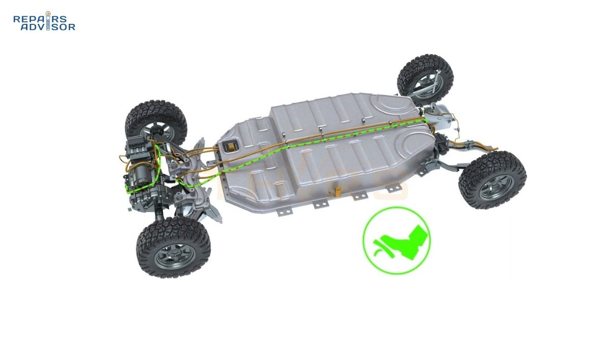
Key Components of ESC Systems
Electronic Stability Control relies on an integrated network of sensors, control modules, and actuators working together to monitor vehicle dynamics and execute corrective interventions. Understanding these components reveals how the system detects and prevents loss of control with such remarkable speed and precision.
Sensor Array
Wheel Speed Sensors (Four Sensors – One Per Wheel)
Each wheel features a dedicated speed sensor that monitors rotational velocity 100 or more times per second. These sensors use either magnetic reluctance or Hall effect technology to detect the passage of teeth on a tone ring (also called a reluctor ring) attached to the wheel hub or axle. When wheel speeds diverge—one wheel spinning faster or slower than the others—ESC recognizes potential traction loss or wheel lockup.
These wheel speed sensors serve double duty, providing data to both the ABS and ESC systems. The sensors must maintain extreme accuracy because ESC calculations depend on detecting subtle differences in wheel rotation. A faulty wheel speed sensor represents the most common ESC system failure, often triggering both ABS and ESC warning lights simultaneously. The How Wheel Speed Sensors Work article provides detailed information about sensor technology, tone ring configurations, and common failure modes.
Modern active wheel speed sensors incorporate amplification circuitry and can detect wheel rotation even at very low speeds, enabling ESC function from 0 MPH upward. Older passive sensors required minimum wheel speed (typically 3-5 MPH) before generating sufficient signal strength for reliable operation.
Steering Angle Sensor
Located in the steering column beneath the steering wheel, the steering angle sensor measures both the position of the steering wheel and the rate at which it’s being turned. This critical input tells ESC where the driver intends to steer the vehicle. Modern steering angle sensors use optical encoders or Hall effect technology with multiple measurement tracks to provide redundant, highly accurate position data.
The sensor reports steering wheel angle in degrees (typically ±720° or more to account for multiple steering wheel rotations) and also calculates steering velocity—how quickly the driver is turning the wheel. This velocity data helps ESC distinguish between gentle lane changes and emergency maneuvers requiring more aggressive intervention.
Steering angle sensors require calibration whenever the steering wheel is removed, after wheel alignment service, or following suspension repairs that might affect steering geometry. Miscalibration can cause ESC to activate inappropriately during straight-line driving or fail to intervene when needed. Professional service facilities use specialized tools to perform this calibration, ensuring the sensor accurately reports “zero degrees” when the wheels point straight ahead. The How Steering Angle Sensors Work article details the calibration process and common sensor issues.
Yaw Rate Sensor (Gyroscope)
The yaw rate sensor—essentially a sophisticated gyroscope—measures vehicle rotation around the vertical axis (the imaginary line running from roof to ground through the vehicle’s center). This sensor detects spin-out conditions before they become visible to the driver or even before significant lateral movement occurs.
Modern yaw sensors use MEMS (Micro-Electro-Mechanical Systems) technology, incorporating a tiny vibrating element whose motion changes when the vehicle rotates. These sensors can detect rotation rates as small as 0.1 degrees per second, providing the sensitivity needed to intervene before small slides become dangerous spins.
Manufacturers typically mount the yaw sensor near the vehicle’s center of gravity to minimize measurement errors caused by body roll or vertical motion. Many modern systems integrate the yaw sensor with the lateral acceleration sensor in a single module, reducing cost and improving packaging efficiency. Technical details about yaw sensor operation and the Coriolis effect that enables rotation measurement can be found in How Yaw Rate Sensors Work.
Lateral Acceleration Sensor (G-Sensor)
The lateral acceleration sensor measures side-to-side forces acting on the vehicle during cornering or sliding. Often called a “G-sensor” because it measures acceleration in terms of gravitational force units, this component detects when the vehicle begins moving sideways—the initial phase of a skid.
During normal cornering, lateral acceleration increases predictably based on vehicle speed and turn radius. When lateral acceleration spikes unexpectedly or exceeds what steering input suggests should occur, ESC recognizes potential loss of control. The sensor helps ESC distinguish between controlled cornering (even at high lateral G forces on a racetrack) and uncontrolled sliding that requires intervention.
As mentioned, most modern vehicles integrate the lateral acceleration sensor with the yaw rate sensor in a combined module. This integration improves correlation between measurements and reduces the number of separate components requiring calibration and service.
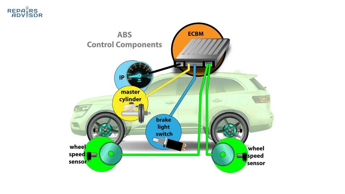
Control Unit Components
ESC Control Module (Electronic Control Unit)
The ESC control module serves as the system’s brain, receiving sensor inputs, performing complex calculations, and commanding corrective actions. This dedicated processor operates independently from the engine control unit (though they communicate via the vehicle’s CAN bus network) and makes stability decisions 25 or more times per second.
The control module compares driver inputs (steering angle, throttle position, brake application) against actual vehicle behavior (wheel speeds, yaw rate, lateral acceleration) to determine whether the vehicle is responding as intended. When discrepancies exceed programmed thresholds, the module calculates which intervention strategy will most effectively restore stability: braking specific wheels, reducing engine power, or both simultaneously.
Modern ESC modules incorporate sophisticated algorithms that account for vehicle load, road slope, tire characteristics, and even driving style. Some systems learn driver behavior over time, adjusting intervention thresholds to match individual preferences while maintaining safety margins. The processing power required for these calculations has increased dramatically since ESC introduction, with current modules performing operations that would have required supercomputers in the 1990s. General information about automotive control modules appears in How ECUs Work.
Hydraulic Control Unit (HCU)
The hydraulic control unit contains the mechanical components that execute ESC commands: a high-pressure pump, solenoid valves for each brake circuit, and accumulator chambers. This unit integrates with the ABS hydraulic system (they share many components) and can independently modulate brake pressure at each wheel without driver input.
When ESC determines that braking intervention is needed, the HCU energizes specific solenoid valves to route pressurized brake fluid to the targeted wheel(s). The system can apply brakes to one, two, three, or all four wheels independently, with pressure modulation occurring multiple times per second during active intervention.
The HCU pump generates hydraulic pressure even when the driver isn’t applying the brakes. During ESC intervention, you might feel brake pedal pulsation or hear the pump motor running—both normal indications that the system is working. The hydraulic control unit represents one of the most complex and expensive ESC components, with failures sometimes requiring complete module replacement. The How Master Cylinder & Booster Work article explains how ESC integrates with the vehicle’s primary braking system.
Actuators and Output Devices
Brake Pressure Modulators
Each wheel’s brake circuit includes a solenoid valve controlled by the ESC module. These valves can increase pressure (applying brakes), hold pressure (maintaining current brake force), or decrease pressure (releasing brakes) independent of driver pedal input. The rapid cycling of these valves during ESC intervention creates the distinctive brake pedal pulsation you might feel during ABS or ESC activation.
Engine Throttle Control
ESC can request engine power reduction through communication with the engine control module. Modern electronic throttle control systems (drive-by-wire) allow ESC to close the throttle valve partially or completely, reducing power delivery to the wheels. Some systems can also retard ignition timing, cut fuel to specific cylinders, or request transmission downshifts to help stabilize the vehicle.
The engine power reduction usually occurs simultaneously with selective braking, creating a coordinated stability intervention. Drivers typically notice a momentary reduction in acceleration during ESC activation, along with the flashing dashboard warning light.
CAN Bus Communication
ESC modules communicate with other vehicle systems via the Controller Area Network (CAN bus), a high-speed digital network that links dozens of control modules. This communication allows ESC to request engine power reduction, receive transmission gear information, coordinate with adaptive cruise control, and integrate with advanced driver assistance systems.
Dashboard Warning Light and Indicators
Every ESC-equipped vehicle includes a dashboard warning light that illuminates during system malfunction and flashes during active ESC intervention. The light typically shows a car with skid marks or a similar stability-related symbol. A separate “ESC OFF” indicator illuminates when the driver manually disables the system (on vehicles that allow deactivation).
How ESC Systems Operate
Electronic Stability Control operates through four distinct phases: continuous monitoring, discrepancy detection, corrective intervention, and graduated recovery. Understanding each phase reveals how the system maintains vehicle stability while remaining transparent during normal driving.
The Detection Phase
Step 1: Continuous Monitoring
ESC begins operating the moment you start your engine and continues functioning until shutdown. The system doesn’t wait for trouble—it actively monitors vehicle dynamics every fraction of a second, establishing baseline expectations for how the vehicle should respond to driver inputs.
During normal driving, the steering angle sensor reports your intended direction, wheel speed sensors confirm all wheels rotate at appropriate speeds for the turn radius, the yaw sensor indicates correct rotation around the vertical axis, and the lateral acceleration sensor shows g-forces consistent with the steering input and vehicle speed. When all these inputs align, ESC remains dormant, allowing you full control without intervention.
The continuous monitoring creates a real-time mathematical model of vehicle behavior. This model incorporates vehicle specifications (wheelbase, track width, center of gravity height), current operating conditions (speed, steering angle, brake application), and expected response (calculated yaw rate, anticipated wheel speeds). ESC compares actual sensor readings against this model hundreds of times per second.
Step 2: Discrepancy Detection
Loss of control begins with small discrepancies between intended and actual vehicle motion. ESC excels at detecting these subtle deviations before they become visible or even perceptible to the driver. The system measures differences in three key comparisons:
Steering Angle vs. Yaw Rate: If you turn the steering wheel 30 degrees right but the yaw sensor indicates the vehicle is only rotating 10 degrees per second (when it should be rotating 25 degrees per second), ESC recognizes understeer—the front wheels are losing grip and the vehicle is plowing forward instead of turning.
Steering Angle vs. Wheel Speeds: During a turn, the outside wheels must rotate faster than inside wheels due to traveling a longer path. ESC calculates expected wheel speed differences based on steering angle and vehicle speed. When wheel speed patterns don’t match these calculations (one wheel spinning much faster, indicating loss of traction), ESC identifies the problem.
Yaw Rate vs. Lateral Acceleration: These two measurements should correlate predictably during normal cornering. When lateral acceleration spikes without corresponding yaw rate increase, or vice versa, ESC detects unusual dynamics that might indicate sliding, wheel lift, or other stability threats.
The system’s response time proves critical. ESC detection typically occurs within 25-50 milliseconds of the initial stability loss—faster than human perception, which requires 100-200 milliseconds to recognize a problem and 200-300 milliseconds more to react.
The Intervention Phase
Step 3: Corrective Action Calculation
Once ESC detects a stability problem, the control module instantly determines the optimal intervention strategy. The system considers multiple factors: severity of the discrepancy, vehicle speed, road surface conditions (inferred from wheel slip patterns), and the specific type of instability detected (understeer vs. oversteer).
The module calculates exactly which wheel or wheels to brake, how much pressure to apply, how long to maintain braking, and whether engine power reduction is needed. These calculations occur in microseconds, with intervention commands transmitted to the hydraulic control unit and engine control module almost instantaneously.
Understeer Correction (Front Wheels Losing Grip)
Understeer occurs when the front wheels lose traction and the vehicle doesn’t turn as sharply as steering input suggests. This “plowing” sensation is common when entering a corner too fast or steering abruptly on slippery surfaces. The vehicle continues relatively straight despite turning the steering wheel.
ESC corrects understeer by applying the brake to the inner rear wheel—the rear wheel on the inside of the turn. This creates a rotational force (yaw moment) that helps pivot the vehicle into the turn. Imagine standing on your left foot while someone pushes your right shoulder backward—you’ll spin left. ESC uses the same principle, creating rotation by generating a braking force offset from the vehicle’s centerline.
Simultaneously, ESC reduces engine power to slow the vehicle, reducing the speed at which you’re attempting the turn. This dual approach—increasing rotation through selective braking while decreasing forward speed—brings the vehicle back to the intended path. Throughout intervention, the driver maintains steering input while ESC assists in achieving the desired direction.
The How Brake-by-Wire Systems Work article explains how modern electronic braking systems enable even faster, more precise ESC interventions compared to conventional hydraulic systems.
Oversteer Correction (Rear Wheels Losing Grip)
Oversteer represents the opposite problem: the rear wheels lose traction and the vehicle rotates more than steering input indicates. This condition can lead to spinouts, with the rear end swinging around dramatically. Oversteer is particularly dangerous because it can develop very quickly, overwhelming driver ability to correct.
ESC addresses oversteer by applying the brake to the outer front wheel—the front wheel on the outside of the turn. This braking force counteracts excessive rotation, stabilizing the rear end and preventing the vehicle from spinning. The action generates a yaw moment opposite to the uncontrolled rotation, effectively “catching” the developing spin.
As with understeer correction, ESC simultaneously reduces engine power. This is particularly important in oversteer situations because continuing to apply throttle while the rear wheels slide can accelerate the spin. Power reduction helps the rear tires regain traction more quickly.
The relationship between electronic power steering and ESC provides interesting integration opportunities. How Electronic Power Steering Works discusses how some advanced systems can even apply corrective steering torque to complement ESC braking intervention.
The Recovery Phase
Step 4: Graduated Release
ESC doesn’t simply switch off once stability improves—the system gradually reduces intervention as the vehicle returns to the driver’s intended path. This graduated approach prevents abrupt transitions that might themselves create instability.
As sensor readings converge toward expected values (steering angle matches yaw rate, lateral acceleration normalizes, wheel speeds equalize), ESC progressively releases brake pressure and allows engine power to return. The intervention might last only a fraction of a second for minor corrections or continue for several seconds during sustained sliding conditions.
Throughout the recovery phase, ESC remains vigilant, ready to intervene again if the vehicle begins losing control. Multiple intervention cycles commonly occur during a single stability event—for example, ESC might correct initial oversteer, then address slight understeer as the vehicle weight transfers forward, then make final minor corrections as dynamics settle.
The dashboard ESC warning light flashes during active intervention, providing visual feedback that the system is working. Once the vehicle stabilizes and ESC intervention ends, the light extinguishes, returning control entirely to the driver.
Real-World Examples
Emergency Lane Change Scenario
You’re traveling at 60 MPH on a dry highway when debris falls from a truck ahead. You instinctively swerve left into the adjacent lane to avoid collision. The sudden steering input combined with weight transfer toward the right side of the vehicle creates oversteer—the rear end begins swinging right.
ESC detects the excessive yaw rate within 30 milliseconds. The control module identifies oversteer and instantly applies the right front brake while reducing throttle. The corrective braking generates a counter-yaw moment that stabilizes the rear end. Total intervention duration: 0.8 seconds. You complete the lane change safely, possibly unaware ESC even activated beyond seeing the warning light flash briefly.
Without ESC, the oversteer would likely continue developing. You might overcorrect by steering hard right, causing the vehicle to swerve violently back toward the debris. This oscillation often leads to loss of control and departure from the roadway or collision with other vehicles.
Icy Corner Scenario
Approaching a familiar corner at your usual speed of 35 MPH, you don’t realize black ice has formed on the shaded inside of the turn. As you turn the steering wheel, the front wheels lose grip on the ice—classic understeer develops. The vehicle continues straight toward the outside of the curve rather than following the road.
ESC instantly detects the mismatch between steering angle and actual vehicle rotation. Within 40 milliseconds, the system applies the left rear brake (inside wheel) to rotate the vehicle into the turn while simultaneously reducing engine power from 150 HP to 80 HP. The selective braking creates the yaw moment needed to start turning despite front wheel loss of traction. The power reduction slows the vehicle from 35 MPH to 28 MPH in 1.5 seconds.
As your front wheels regain grip (either by transitioning off the ice or due to the reduced speed), ESC gradually releases intervention. Total active ESC time: 2.3 seconds. You navigate the corner successfully, though at reduced speed. The alternative scenario without ESC typically involves the vehicle departing the roadway into a ditch or striking the guardrail.
Benefits and Effectiveness
Electronic Stability Control delivers measurable, significant safety improvements across diverse driving conditions and vehicle types. Extensive real-world crash data and controlled testing demonstrate why ESC became legally mandated worldwide.
Crash Prevention Statistics
The National Highway Traffic Safety Administration conducted comprehensive analysis of crash data from millions of vehicles over multiple years. Their findings reveal that ESC prevents approximately 50% of fatal single-vehicle crashes—accidents where a vehicle leaves the roadway and strikes a fixed object, rolls over, or otherwise crashes without colliding with another vehicle.
For SUVs, pickups, and other vehicles with higher centers of gravity, ESC proves even more effective. The system reduces rollover risk by 80%, addressing one of the most dangerous crash types. Rollovers account for a disproportionate percentage of fatal accidents because vehicle occupants are subjected to extreme forces and risk ejection even when belted.
Overall, the Insurance Institute for Highway Safety estimates that ESC could prevent approximately one-third of all fatal crashes if every vehicle on the road featured the technology. This safety improvement rivals the impact of seatbelts and airbags, representing one of the most significant safety advances in automotive history.
In Europe, researchers calculated that ESC saved approximately 15,000 lives between its introduction in the mid-1990s and 2020. As older vehicles without ESC gradually age out of the fleet and newer ESC-equipped vehicles become universal, these numbers will continue improving.
Situational Benefits
Wet Road Performance
Rain-slicked roads reduce tire traction by 30-50% compared to dry conditions. This reduction makes vehicles more susceptible to hydroplaning (where tires lose contact with pavement and ride on a layer of water) and increases stopping distances significantly.
ESC maintains directional control during emergency braking on wet surfaces by working in conjunction with ABS. When wheels begin locking despite ABS intervention, ESC recognizes that available traction has decreased dramatically and adjusts intervention strategies accordingly. The system can detect partial hydroplaning (one or two wheels losing road contact) before complete control loss occurs.
During cornering on wet roads, ESC intervenes earlier and more gradually than on dry surfaces, recognizing the reduced grip available. This proactive approach helps drivers maintain stability without feeling the abrupt intervention that might occur during dry-surface corrections.
Understanding how brake components perform in wet conditions enhances appreciation for ESC operation. How Brake Pads & Rotors Work explains the friction dynamics between pads and rotors under various environmental conditions.
Snow and Ice Driving
Winter conditions present the most challenging environment for vehicle control. ESC proves particularly valuable on snow and ice, where available traction can drop to 20% or less of dry-pavement levels.
The system detects wheel slip instantly—much faster than drivers can perceive. On slippery surfaces, ESC might activate multiple times per minute during normal driving as tires encounter patches of varying grip levels. Each intervention helps maintain stability without requiring driver awareness or action.
However, ESC cannot overcome fundamental physics. The system works within the limits of available tire traction—it cannot create grip where none exists. Even with ESC, drivers must reduce speed appropriately for conditions, allow extra following distance, and avoid aggressive maneuvers. ESC significantly improves safety margins but doesn’t eliminate the need for cautious winter driving.
Winter tires dramatically enhance ESC effectiveness. The improved grip provided by winter tire compounds and tread patterns gives ESC more traction to work with, allowing more effective stability interventions. The combination of ESC and proper winter tires provides the best possible safety during cold-weather driving.
Emergency Maneuvers
Avoiding sudden obstacles—animals darting into the road, debris from other vehicles, or stopped traffic ahead—requires quick, often instinctive steering inputs. These emergency maneuvers frequently exceed the vehicle’s stability limits, particularly when combined with braking.
ESC excels during obstacle avoidance situations. The system helps drivers maintain control through the initial evasive steering, prevents overcorrection as they straighten the vehicle, and manages weight transfer throughout the entire sequence. Many drivers report that ESC allowed them to avoid crashes that would have been impossible to navigate without electronic assistance.
The system also helps during panic braking combined with steering—a scenario that often leads to loss of control without ESC. Drivers naturally try to both brake hard and steer around obstacles simultaneously. This combination challenges vehicle dynamics, but ESC manages brake force distribution and stability to maintain control during these complex maneuvers.
Limitations and Boundaries
What ESC Cannot Do
Despite its remarkable effectiveness, ESC operates within fundamental physical constraints:
ESC does not increase available tire traction. The system can only work with the grip provided by your tires on the current road surface. If you enter a corner at 60 MPH where maximum safe speed is 40 MPH, ESC might help slow the vehicle and maintain better control than without intervention, but cannot prevent the crash entirely.
ESC cannot overcome excessive speed for conditions. Physics determines how much force tires can generate before losing grip. No electronic system can change these physical limits. ESC provides a safety margin and helps during unexpected events, but driving within safe speeds for conditions remains essential.
The system proves less effective during hydroplaning. When wheels lose contact with the pavement entirely (complete hydroplaning), ESC has no braking force to apply for corrective action. The system works best when at least partial tire-to-road contact exists.
ESC is not a substitute for safe driving practices. The technology assists skilled, attentive drivers but cannot compensate for reckless behavior, distracted driving, or poor decision-making. ESC represents an additional safety layer, not a license to drive beyond your or your vehicle’s limits.
Driver Responsibilities
Maintaining safe vehicle speed for road and weather conditions remains your primary responsibility. ESC works best when drivers operate within reasonable limits and face unexpected challenges requiring stability assistance.
Allow adequate following distance—ESC can help maintain control during emergency braking but cannot reduce stopping distances beyond what physics allows. The system helps you steer during hard braking (unlike vehicles without ABS), but requires sufficient distance to avoid collision.
Keep tires properly inflated and maintained. ESC calculations depend on accurate wheel speed readings, which require properly functioning tires. Underinflated, worn, or mismatched tires compromise both available traction and ESC effectiveness.
Understand that ESC assists rather than replaces driver judgment. When the warning light flashes frequently during normal driving, you’re likely driving too aggressively for conditions. Slow down and adjust driving style to match available traction.
ESC Warning Light and System Status
The dashboard warning light provides critical information about ESC operation and system health. Understanding what different light patterns indicate helps you distinguish normal operation from malfunctions requiring attention.
Dashboard Indicator Meanings
Flashing ESC Light (Rapid Blinking)
When the ESC warning light flashes rapidly, the system is actively intervening to maintain vehicle stability. This represents normal operation—ESC has detected loss of traction or control and is applying corrective braking and throttle reduction.
You might notice the flashing light during:
- Accelerating on slippery surfaces (snow, ice, wet pavement)
- Cornering near traction limits
- Emergency lane changes or obstacle avoidance
- Driving on surfaces with varying grip levels (patchy ice, gravel)
The flashing light should extinguish within seconds as the vehicle stabilizes. Frequent flashing during normal driving conditions suggests you’re driving too aggressively for available traction—reduce speed and moderate steering inputs.
Steady ESC Light (Continuously Illuminated)
A steady, continuously illuminated ESC warning light indicates system malfunction. ESC has detected an internal fault and has disabled stability control functionality until repairs restore proper operation.
Common causes include:
- Wheel speed sensor failure or wiring damage
- Steering angle sensor miscalibration
- Yaw rate or lateral acceleration sensor malfunction
- ABS hydraulic control unit problems
- Low battery voltage affecting sensor operation
- Communication errors on the CAN bus network
When the steady light appears, ESC protection is unavailable. Your vehicle will still drive normally and the basic ABS should continue functioning (unless the problem affects ABS components), but you’ve lost the stability assistance ESC provides. Drive cautiously and schedule diagnostic service promptly.
Modern vehicles (2012 and newer in the US) must keep the malfunction light illuminated whenever ESC isn’t fully functional, ensuring drivers remain aware of the system’s status.
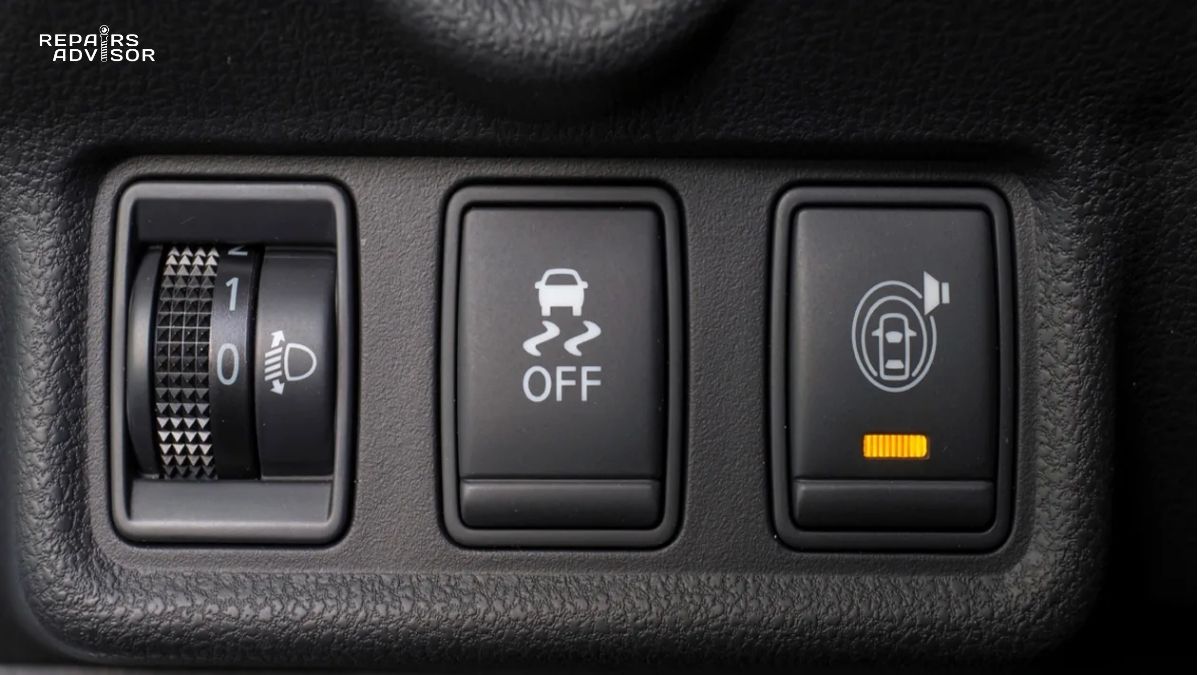
ESC OFF Light
Some vehicles allow drivers to manually disable ESC by pressing a dedicated button (usually labeled with a car and skid marks icon, with “OFF” text). When ESC is intentionally disabled, a separate “ESC OFF” warning light illuminates to remind you the system is inactive.
Most vehicles require holding the ESC OFF button for several seconds (preventing accidental deactivation) and will automatically re-enable ESC at the next ignition cycle. Some performance vehicles offer multiple modes—completely off, sport mode (relaxed intervention thresholds), or normal mode (full ESC functionality).
When ESC Can Be Turned Off
Legitimate Use Cases for ESC Deactivation
While ESC should remain active during normal road driving, specific situations benefit from temporary system deactivation:
Stuck in deep snow, sand, or mud: When wheels need sustained spinning to gain momentum and break free from deep mud or snow, ESC intervention (which prevents wheel spin) can actually prevent escape. Disabling ESC temporarily allows aggressive throttle application and wheel spin needed to rock the vehicle free or gain traction in deep conditions.
Using snow chains: Some vehicles’ owner manuals recommend ESC deactivation when using snow chains because the chains alter the expected wheel speed patterns. ESC might interpret the chain-modified rotation as wheel slip and intervene inappropriately.
Track day or competition driving: On closed courses where drivers intentionally explore vehicle limits, ESC intervention can interfere with performance driving techniques like controlled drifts or late braking. Professional driver training often includes ESC-off exercises to teach vehicle dynamics without electronic assistance.
Rock crawling in 4WD vehicles: Extreme off-road driving at very low speeds over obstacles sometimes requires allowing individual wheels to spin or lift completely. ESC might misinterpret these conditions as loss of control. Some 4WD vehicles include specialized “rock crawl” modes that partially modify ESC parameters rather than disabling the system entirely.
Dyno testing or maintenance procedures: Some diagnostic procedures and chassis dynamometer testing require ESC deactivation to prevent the system from intervening when wheel speeds don’t match vehicle speed.
Important Safety Reminder
Under normal road driving conditions—highways, city streets, rural roads, even spirited driving on public roads—ESC should remain active. The system doesn’t limit normal driving performance or enjoyment but provides critical protection during unexpected loss of traction or emergency maneuvers.
If you disable ESC for legitimate reasons (stuck in snow, for example), re-enable the system immediately afterward. Most vehicles automatically re-enable ESC at the next startup as a safety measure, but don’t rely on this—manually turn the system back on as soon as the special circumstance ends.
The How Parking Brake Systems Work article discusses another critical safety system that operates independently of ESC but shares some common diagnostic approaches.
Common Problems and Troubleshooting
Like all vehicle systems, ESC can develop faults that compromise its protective function. Understanding common problems, their symptoms, and diagnostic approaches helps you determine whether issues require immediate professional attention or represent simpler correctable conditions.
Frequent ESC Issues
Wheel Speed Sensor Failures (Most Common Problem)
Wheel speed sensors represent the most frequent ESC component failure, accounting for approximately 60-70% of ESC-related problems. These sensors operate in harsh environments—exposed to road debris, water, salt, temperature extremes—making them vulnerable to damage and corrosion.
Symptoms: ESC warning light illuminated constantly, often accompanied by ABS warning light. Some vehicles display traction control warning lights simultaneously. Diagnostic trouble codes indicate specific sensor circuit faults.
Causes:
- Physical sensor damage from road debris impact
- Corroded wiring connectors (particularly in salt-belt regions)
- Damaged tone ring (reluctor ring) teeth on wheel hub
- Excessive air gap between sensor and tone ring due to worn wheel bearings
- Internal sensor element failure
Diagnosis: Professional scan tools read specific fault codes indicating which sensor circuit has failed (left front, right rear, etc.). Technicians verify the diagnosis by checking sensor resistance, examining wiring for damage, inspecting tone ring condition, and monitoring live sensor data.
Solution: Replace the faulty sensor and repair any damaged wiring. Cost typically ranges from $100-$300 per sensor including parts and labor for straightforward replacements. Complications like seized sensors or corroded mounting brackets can increase costs.
For detailed information about a specific wheel speed sensor diagnostic code, see Code C0031 – Left Front Wheel Speed Sensor Circuit.
Steering Angle Sensor Miscalibration
The steering angle sensor requires calibration to establish the “zero point”—the steering wheel position corresponding to wheels pointing straight ahead. This calibration can be lost during battery disconnect, steering wheel removal, wheel alignment service, or following certain suspension repairs.
Symptoms: ESC warning light illuminated, ESC activating inappropriately during straight-line driving, steering wheel not centered when driving straight, ESC intervention during gentle turns where no stability assistance should be needed.
Causes:
- Steering wheel removed and reinstalled in different position
- Battery disconnection clearing stored calibration values
- Wheel alignment performed without subsequent sensor recalibration
- Front-end collision affecting suspension geometry
- Steering angle sensor internal fault (less common than miscalibration)
Diagnosis: Scan tools display current steering angle sensor reading. When wheels point straight ahead and steering wheel is centered, the sensor should read 0 degrees (±2-3 degrees tolerance). Significant offset indicates miscalibration.
Solution: Perform steering angle sensor calibration using manufacturer-specified procedure. This typically involves:
- Ensuring vehicle is on level ground with wheels straight
- Cycling steering wheel full left, full right, then center
- Using scan tool to command calibration procedure
- Verifying successful calibration
Professional calibration costs $100-$200 at dealerships or independent shops with appropriate equipment. Some vehicles allow DIY calibration using basic procedures (turn steering lock-to-lock specific number of times with ignition on), but professional calibration with scan tool verification provides better reliability.
Yaw Rate Sensor Failure
The yaw rate sensor (often integrated with lateral acceleration sensor) measures vehicle rotation and sideways acceleration. While more reliable than wheel speed sensors due to protected mounting locations, these sensors can fail.
Symptoms: ESC disabled, warning light continuously on, no ESC intervention even during obvious traction loss, diagnostic codes indicating yaw sensor circuit malfunction.
Causes:
- Internal sensor element failure
- Wiring damage or connector corrosion
- Mounting bracket failure causing sensor misalignment
- Water intrusion damaging sensor electronics
- Impact damage from collision affecting sensor mounting location
Diagnosis: Scan tool monitors yaw sensor output during vehicle movement. Technicians verify the sensor responds correctly to vehicle rotation and that output values remain within expected ranges. Zero movement reading during turns confirms sensor failure.
Solution: Replace the yaw rate/lateral acceleration sensor module. The sensor is typically located under the center console, beneath front seats, or near the vehicle center. Cost ranges from $200-$400 for parts plus $100-$200 labor, depending on sensor location accessibility.
For comprehensive sensor operation details, visit How Yaw Rate Sensors Work.
Low Battery Voltage
ESC systems prove particularly sensitive to electrical voltage. When battery voltage drops below specified levels (typically 11.5-12.0 volts), ESC may disable itself as a precaution, illuminating warning lights.
Symptoms: Multiple warning lights including ESC, ABS, traction control, and possibly others. Lights may appear intermittently, particularly during engine start when voltage drops briefly.
Causes:
- Weak or failing battery unable to maintain proper voltage
- Failing alternator not charging battery adequately
- Corroded battery terminals creating resistance
- Parasitic electrical drain depleting battery when vehicle parked
Diagnosis: Battery voltage test (should be 12.4+ volts engine off, 13.8-14.4 volts running), charging system test, visual inspection of battery terminals and cables.
Solution:
- Replace battery if testing shows capacity loss or inability to hold charge ($100-$200)
- Repair charging system if alternator output inadequate ($300-$600 for alternator replacement)
- Clean and tighten battery terminals if corrosion present (DIY task)
- Identify and repair parasitic drain if present
After correcting voltage issues, use scan tool to clear fault codes. ESC warning light should extinguish, restoring system function.
ABS Module Failures
Since ESC shares the ABS hydraulic control unit and much of the control electronics, ABS module failures affect ESC operation. These failures represent more serious problems requiring expensive repairs.
Symptoms: Both ESC and ABS warning lights illuminated, reduced or absent brake pedal pulsation during hard stops, potential changes in brake pedal feel, multiple fault codes stored.
Causes:
- Internal hydraulic valve failure
- Pump motor failure preventing pressure generation
- Control module electronic failure
- Moisture intrusion causing internal corrosion
- Physical damage from collision or corrosion
Diagnosis: Scan tool identifies specific ABS module faults. Technicians may perform hydraulic pressure tests, valve function tests, or electrical circuit verification to pinpoint failure mode.
Solution: ABS module replacement or professional rebuild. Costs range dramatically:
- Remanufactured module: $500-$1,000
- New OEM module: $1,000-$2,000
- Professional rebuild service: $300-$600 plus shipping/downtime
- Labor for replacement: $200-$400
The How ABS Systems Work article provides detailed information about ABS components and operation.
Troubleshooting Steps for DIY Enthusiasts
Before seeking professional diagnosis, DIY-capable vehicle owners can perform several basic checks:
1. Check Tire Pressure (All Four Tires)
Uneven or incorrect tire pressure causes wheel speed variations that can trigger ESC faults or inappropriate activation. Verify all tires match recommended pressure (found on driver door jamb placard). Adjust as needed.
2. Inspect Wheel Speed Sensor Wiring
Visually examine wiring near each wheel for obvious damage, cuts, or disconnected connectors. Wheel speed sensor wires are particularly vulnerable during brake service, suspension work, or wheel bearing replacement. Look for:
- Severed or kinked wires
- Corroded connectors
- Loose or disconnected plugs
- Wires rubbing against rotating components
3. Verify Battery Voltage
Use a multimeter to measure battery voltage:
- Engine off: Should read 12.4-12.6 volts (fully charged battery)
- Engine running: Should read 13.8-14.4 volts (charging system working)
Lower readings suggest battery or charging system problems that might affect ESC operation.
4. Scan for Fault Codes
ESC diagnostic codes require an ABS-capable scan tool—basic OBD-II code readers that only access engine codes cannot communicate with ABS/ESC modules. Quality ABS scanners cost $100-$300 for DIY versions or can be borrowed from auto parts stores (some loan tools for free).
Scan for codes in:
- ABS module
- ESC module (sometimes separate from ABS)
- Body control module (some steering angle sensor codes store here)
Record all codes before clearing them. Research specific codes to understand which components or circuits have faulted.
5. Check Brake Fluid Level
Low brake fluid affects ABS operation, which impacts ESC. Locate the brake fluid reservoir (usually near the brake master cylinder under the hood, driver’s side). Fluid level should be between MIN and MAX marks. Low fluid indicates brake pad wear (pads wearing down displaces fluid into calipers) or possible leak.
Safety note: Do not drive with brake warning light illuminated or extremely low brake fluid. This indicates potentially dangerous brake system problems requiring immediate professional attention.
When to Seek Professional Help
Certain ESC problems exceed DIY diagnostic capabilities and require professional service:
ESC Light Remains On After Basic Checks
If you’ve verified tire pressure, checked for obvious wiring damage, confirmed battery voltage is adequate, and scanned for codes, but the ESC light remains illuminated, professional diagnosis becomes necessary. Technicians have access to:
- Manufacturer-specific diagnostic software
- Component-level testing equipment
- Technical service bulletins describing known issues
- Specialized calibration tools
Multiple Warning Lights Illuminated Simultaneously
When ESC, ABS, traction control, and potentially other warning lights illuminate together, the problem likely involves shared systems (like the CAN bus network, main electrical system, or ABS hydraulic unit). These complex problems require systematic professional diagnosis.
Abnormal Brake Pedal Feel or Operation
Changes in brake pedal height, firmness, or travel can indicate ABS hydraulic control unit problems affecting ESC. Any brake system concerns should receive immediate professional evaluation given the safety-critical nature of braking.
Recent Collision or Suspension Work
Front-end collisions can damage wheel speed sensors, steering angle sensors, wiring, or sensor mounting points. Suspension repairs might disturb sensor wiring or require steering angle sensor recalibration. Professional inspection ensures proper system restoration after these events.
Unable to Clear Fault Codes
If you scan, record, and clear fault codes, but they immediately return, the underlying problem persists and requires repair. Repeatedly clearing codes without fixing the actual fault wastes time and leaves you without ESC protection.
For information about communication bus errors that can affect multiple systems, see Code U0001 – High Speed CAN Communication Bus.
Maintenance and Best Practices
Electronic Stability Control operates largely as a maintenance-free system, requiring no scheduled component replacement under normal circumstances. However, supporting systems and related components benefit from regular maintenance that ensures ESC can function optimally when needed.
ESC-Specific Maintenance Requirements
System Self-Checks (Automatic)
ESC performs comprehensive self-diagnostics every time you start your vehicle. The control module checks sensor circuits, verifies communication with other modules, and confirms hydraulic actuator function. This automatic monitoring requires no driver action.
During the brief period after ignition (typically 2-3 seconds), dashboard warning lights illuminate as part of the bulb check and system initialization. All lights should extinguish once the engine starts and self-checks complete successfully.
Sensor Cleaning During Brake Service
When brake service involves removing wheels, technicians should visually inspect wheel speed sensors and clean any accumulated debris or corrosion from sensor faces and tone rings. This simple preventive measure helps maintain reliable sensor operation.
Road grime, brake dust, and corrosion can accumulate on tone rings, potentially affecting wheel speed sensor signal quality. Cleaning these components during routine brake pad replacement prevents minor contamination from developing into sensor failures.
Wiring Inspection During Routine Service
Periodic visual inspection of ESC sensor wiring (particularly wheel speed sensor wiring near wheels) helps identify developing problems before complete failures occur. Technicians should check for:
- Chafed or damaged wire insulation
- Corroded connectors
- Wires routed too close to moving components
- Loose or unsecured wiring that might contact rotating parts
Early detection allows simple repairs (re-routing wires, cleaning connectors, replacing damaged sections) rather than waiting for complete circuit failure.
Related System Maintenance
ABS System and Brake Fluid
ESC shares the ABS hydraulic system, making brake fluid maintenance critical for both systems. Brake fluid absorbs moisture over time (it’s hygroscopic), which lowers the fluid’s boiling point and can cause corrosion in ABS/ESC hydraulic components.
Recommended maintenance: Flush and replace brake fluid every 2-3 years regardless of mileage. Some manufacturers specify longer intervals (or no interval at all), but 2-3 years provides good insurance against moisture-related problems.
The How Brake Fluid Works article explains fluid properties, moisture absorption, and why regular replacement matters.
Brake Components (Pads, Rotors, Calipers)
Well-maintained brake components ensure ESC has reliable hardware to execute stability interventions. Follow manufacturer-recommended service intervals:
- Brake pad inspection: Every oil change or at minimum annually
- Brake pad replacement: When friction material reaches minimum thickness (typically 3-4mm)
- Rotor replacement or resurfacing: As needed based on wear, warping, or minimum thickness specifications
- Caliper service: Clean, lubricate slide pins during pad replacement; rebuild or replace calipers showing leaks or seized pistons
For comprehensive brake component information, visit How Drum Brakes Work to understand rear drum brake systems common on many vehicles.
Tire Maintenance
Tires directly affect both ESC performance and the traction ESC needs to function effectively:
Rotation: Rotate tires every 5,000-7,500 miles following manufacturer-specified pattern. Even wear across all four tires ensures consistent wheel speed readings and balanced traction.
Inflation: Check tire pressure monthly. Maintain manufacturer-recommended pressure (found on door jamb placard). Underinflated tires reduce traction, increase rolling resistance, and can trigger false ESC interventions due to altered rolling diameter.
Replacement: Replace all four tires together when possible. Mismatched tire sizes, tread depths, or designs can cause wheel speed variations that affect ESC calculations. Minimum acceptable tread depth: 4/32″ (some recommend replacement at 6/32″ for optimal wet traction).
Seasonal changeover: In regions with winter weather, install winter tires on all four positions. “All-season” tires provide marginal winter performance—dedicated winter tires offer 25-50% more grip in snow and ice, dramatically improving ESC effectiveness.
Wheel Alignment
Annual alignment checks ensure proper suspension geometry and minimize tire wear. Alignment service affects ESC indirectly through:
- Steering angle sensor calibration requirements: After alignment, steering angle sensor recalibration is essential
- Tire wear patterns: Poor alignment causes uneven wear, necessitating premature replacement
- Vehicle handling: Proper alignment maximizes tire contact patch and traction
Battery Maintenance
Electrical system health directly impacts ESC operation:
- Annual testing: Have battery tested during routine service to check capacity and charging system output
- Replacement interval: Replace batteries proactively every 3-5 years before unexpected failure
- Terminal maintenance: Clean battery terminals annually to prevent corrosion-related voltage drops
Maximizing ESC Effectiveness
Using All Four Same-Type Tires
ESC calculations assume all four tires have identical diameter and rolling characteristics. Mixing tire brands, models, sizes, or tread depths creates wheel speed discrepancies that ESC must account for.
While ESC can compensate for minor differences, significant mismatches reduce system effectiveness. Best practice: Replace all four tires simultaneously with identical make, model, and size.
Avoiding Aftermarket Wheel/Tire Packages That Alter Rolling Diameter
Installing larger or smaller wheels/tires than OEM specifications changes wheel rotation speed relative to vehicle speed. If not recalibrated, ESC may misinterpret normal wheel speeds as slip conditions.
If you install non-standard wheel/tire combinations:
- Ensure overall diameter matches OEM specifications (within 3%)
- Have speedometer and ESC system recalibrated if diameter changes significantly
- Consult with knowledgeable tire shops or dealerships before installation
Maintaining Proper Load Distribution
Heavily loading one end of the vehicle (rear cargo area with front seats empty, for example) alters weight distribution and handling characteristics. While ESC compensates for loading to some degree, extreme weight imbalances can exceed the system’s design parameters.
Distribute cargo evenly when possible and avoid exceeding vehicle load ratings.
Professional Service Recommendations
Annual Brake System Inspection
Comprehensive brake inspection should include:
- Pad thickness measurement
- Rotor condition assessment
- Caliper operation verification
- Fluid level and condition check
- Wheel speed sensor visual inspection
- Brake line and hose condition
Diagnostic Scan If ESC Light Appears
Don’t ignore ESC warning lights. Have the system scanned as soon as practical after the light illuminates. Early diagnosis often reveals simple problems (low battery voltage, loose connector) before they develop into more expensive failures.
Wheel Speed Sensor Replacement When ABS Issues Occur
If you experience ABS activation during normal stops (when wheels aren’t actually locking) or ABS warning lights, have wheel speed sensors tested. Faulty sensors often show intermittent problems before failing completely.
Steering Angle Sensor Calibration After Collision Repair
Front-end collision repair can affect suspension geometry, steering components, or sensor alignment. Professional recalibration after repairs ensures ESC has accurate steering position data.
For manufacturer-specific service information and repair procedures, consult brand-specific repair manuals:
Conclusion
Electronic Stability Control represents one of the most significant safety innovations in automotive history, preventing approximately 50% of fatal single-vehicle crashes and reducing rollover risk by 80%. The system uses sophisticated sensors—wheel speed sensors, steering angle sensors, yaw rate sensors, and lateral acceleration sensors—to continuously monitor vehicle dynamics hundreds of times per second. When ESC detects discrepancies between your intended steering direction and actual vehicle motion, it intervenes automatically by applying brakes to individual wheels and reducing engine power, helping maintain control during emergency maneuvers and slippery conditions.
The technology works in conjunction with ABS and traction control systems, integrating brake modulation, throttle management, and advanced sensor monitoring to address both understeer and oversteer situations. From emergency lane changes to icy corners, ESC operates transparently during normal driving while providing critical assistance when you need it most. Understanding how the system works—from the detection phase through intervention and recovery—reveals the sophisticated engineering protecting you and your passengers during every drive.
When Professional Consultation is Essential
While ESC operates largely maintenance-free, certain situations require professional attention:
Any illuminated ESC warning light warrants diagnostic scanning to identify the specific fault. Don’t ignore these warnings—they indicate lost stability protection that significantly increases crash risk during emergency situations.
Abnormal brake system behavior including unusual pedal feel, changes in pedal height, or brake warning lights demands immediate professional evaluation. ESC shares critical components with your braking system, and any brake concerns affect both conventional and electronic braking functions.
After collision or suspension damage, professional inspection ensures sensor alignment, wiring integrity, and proper system calibration. Front-end impacts commonly damage wheel speed sensors, steering angle sensors, or sensor mounting points.
When diagnostic codes indicate sensor failures, replacement requires proper part selection and often calibration procedures. Wheel speed sensors, steering angle sensors, and yaw sensors must meet exact specifications for reliable ESC operation.
Before attempting ESC component repairs, recognize that the system includes safety-critical brake components. Hydraulic system work requires proper procedures, torque specifications, brake bleeding technique, and safety protocols beyond typical DIY capabilities.
Safety Disclaimer
Electronic Stability Control is a critical safety system that prevents thousands of crashes annually. While understanding ESC operation proves valuable, diagnosis and repair of ESC components requires:
Specialized diagnostic equipment: ABS-capable scan tools that can communicate with stability control modules, display live sensor data, and perform calibration procedures. Basic OBD-II code readers cannot access ESC systems.
Factory service procedures: Manufacturer-specific calibration steps, torque specifications, and testing protocols ensure proper system restoration after repairs.
Professional training: Hydraulic brake system work demands knowledge of proper bleeding procedures, fluid handling, component assembly sequences, and safety precautions.
Proper safety protocols: Brake system service involves supporting vehicles safely, preventing fluid contamination, protecting electrical connections, and verifying system operation before returning vehicles to service.
DIY-appropriate tasks include visual inspection of sensor wiring and connectors, tire maintenance (pressure, rotation, replacement), basic troubleshooting using scan tools to identify fault codes, and brake fluid level checks. Professional service is required for sensor replacement and calibration, hydraulic system repairs, control module replacement or programming, and any work involving brake hydraulic components.
Final Thoughts
Electronic Stability Control has transformed vehicle safety, making today’s cars dramatically safer than those from just two decades ago. The technology represents the culmination of decades of research into vehicle dynamics, sensor technology, and control systems. As you drive, ESC works silently in the background—monitoring, calculating, preparing to intervene if needed—serving as your invisible safety net during unexpected emergencies.
Maintaining related systems ensures ESC can function at peak effectiveness when you need it most. Well-maintained tires provide the traction ESC needs to work with. Properly functioning brakes give ESC reliable hardware for intervention. A healthy battery supplies the electrical power sensors require. Regular maintenance of these supporting systems maximizes the safety benefits ESC provides.
Drive safely, maintain your vehicle properly, and appreciate the sophisticated technology working constantly to keep you on your intended path. ESC doesn’t replace careful driving, appropriate speed for conditions, or defensive driving techniques—but it provides crucial assistance during those moments when physics, road conditions, or unexpected events challenge your vehicle’s stability limits.
For comprehensive information about braking and stability systems, explore the Vehicle Safety category and related articles including How Traction Control Systems Work and How Brake Boosters Work. Understanding these interconnected safety systems helps you appreciate the comprehensive protection modern vehicles provide.