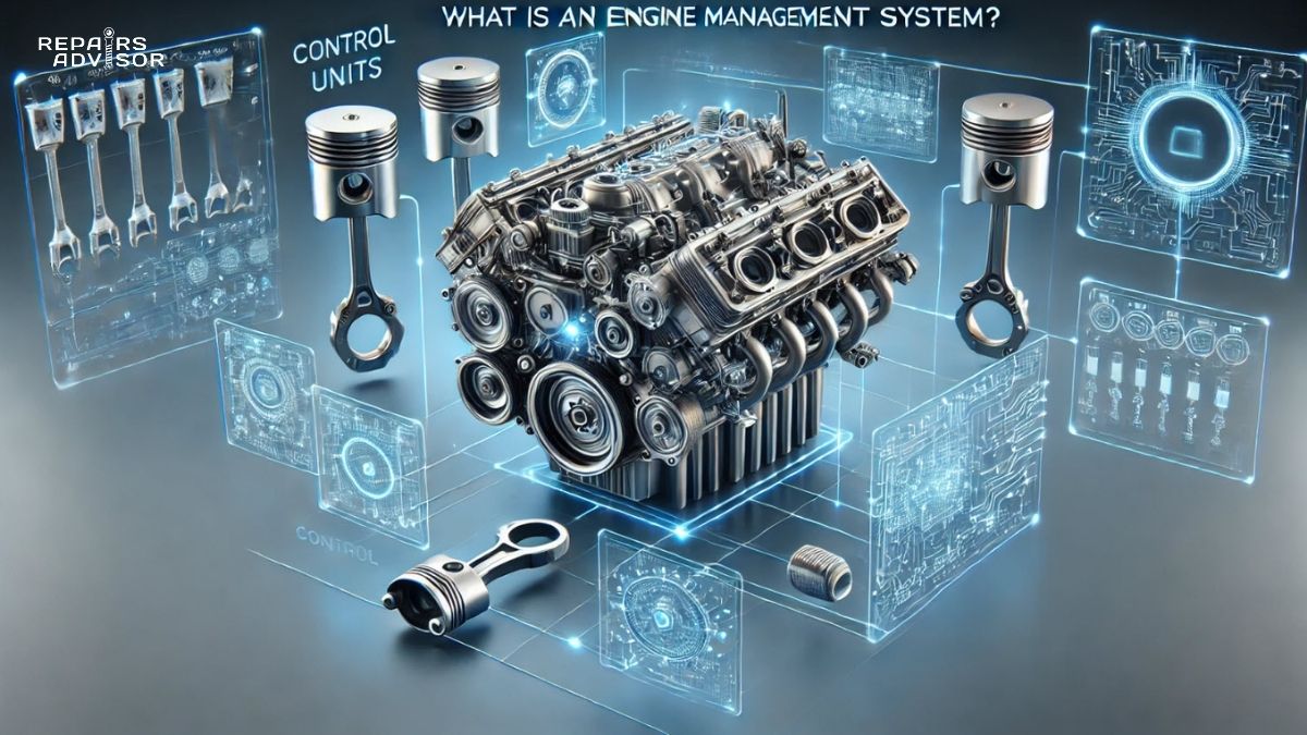
Why Variable Valve Timing Is Critical for Engine Performance
Variable valve timing (VVT) represents one of the most significant advances in modern engine technology, dynamically adjusting valve opening and closing timing to optimize engine performance across all operating conditions. This sophisticated system allows engines to achieve peak efficiency, reduced emissions, and enhanced power delivery by adapting valve timing to match current driving demands rather than using fixed timing compromises.
Modern VVT systems deliver measurable benefits across the entire engine operating range, with manufacturers reporting 5-10% fuel economy improvements and up to 15% emission reductions compared to fixed timing systems. At low RPM (1000-2500), the system advances intake timing by 15-25 degrees for maximum torque and improved fuel economy, while at high RPM (4000+) it maximizes airflow for peak power output by optimizing overlap timing. The technology reduces harmful emissions by up to 15% while improving fuel efficiency by 5-10% compared to fixed timing systems. When VVT systems malfunction, drivers typically experience rough idling, reduced power, poor fuel economy, and illuminated check engine lights – symptoms that significantly impact both performance and operating costs.
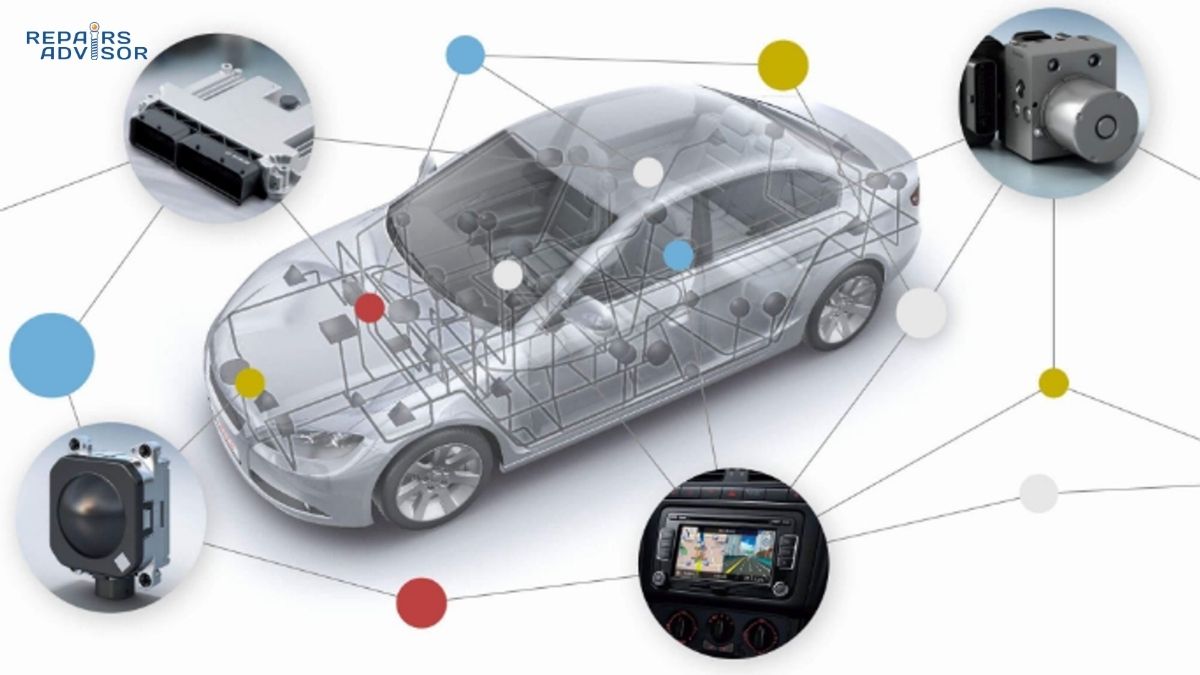
Quick Facts: VVT systems continuously adjust intake and/or exhaust valve timing using oil pressure or electromagnetic actuators controlled by the engine management system. Professional-level diagnostic equipment is typically required for proper VVT system troubleshooting, though basic maintenance like regular oil changes is critical for system longevity.
Safety Note: VVT system components operate under high oil pressure and precise tolerances. Always consult manufacturer specifications before attempting any VVT-related repairs, as improper timing adjustments can cause severe engine damage.
Variable Valve Timing Parts and Construction Explained
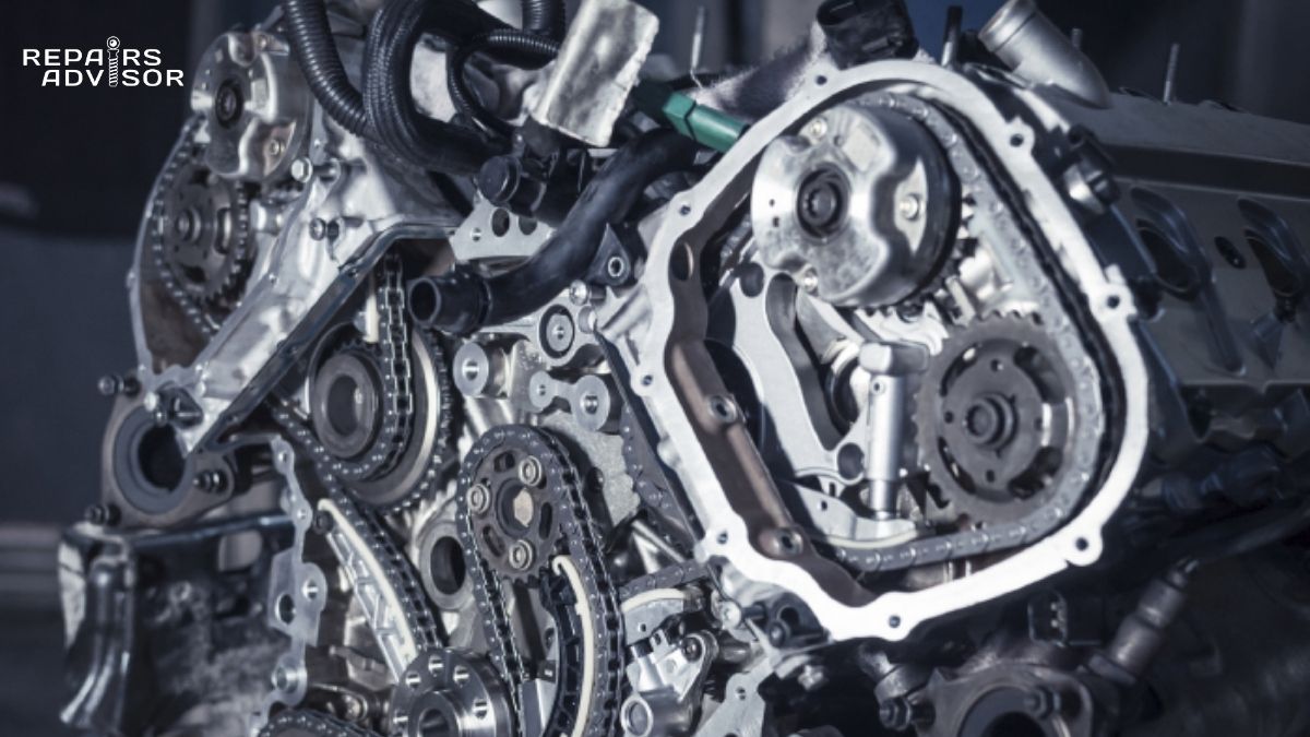
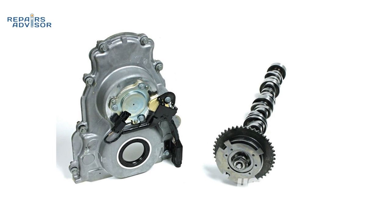
Variable valve timing systems consist of several precision-engineered components working together to provide dynamic valve timing control. The heart of most VVT systems is the cam phaser (also called a VVT actuator), a hydraulically-operated device mounted on the camshaft that can advance or retard valve timing by rotating the camshaft relative to its drive sprocket. These phasers typically use internal vanes and oil galleries to create rotational force, with construction materials including hardened steel housings and aluminum alloy internal components designed for millions of operation cycles.
The VVT solenoid (oil control valve) serves as the electronic interface between the engine control unit and the hydraulic cam phaser. This electromagnetically-controlled valve precisely regulates oil flow and pressure to the cam phaser, enabling smooth timing transitions. Modern solenoids incorporate variable duty cycle control for precise positioning rather than simple on/off operation. The solenoid body typically features corrosion-resistant materials and O-ring seals to maintain hydraulic integrity in the harsh engine environment.
Supporting components include the timing chain tensioner system, which maintains proper chain tension during VVT operation, and specialized sensors that provide feedback to the ECU. The camshaft position sensor and crankshaft position sensor work together to provide real-time timing information, enabling closed-loop control of the VVT system. Oil passages machined into the cylinder head and camshaft carry pressurized engine oil to the cam phasers, while check valves prevent timing drift when the engine is shut down.
Quality variations exist between OEM and aftermarket VVT components. OEM phasers typically offer superior long-term reliability and precise control, while performance aftermarket units may provide wider timing adjustment ranges for modified engines. Budget replacement parts often lack the precision tolerances required for optimal VVT operation and may cause timing-related engine problems.
How Variable Valve Timing Works: Step-by-Step Operation
Step 1: System Initialization and Baseline Timing
When the engine starts, the VVT system begins in a default “limp home” position, typically at a predetermined baseline timing setting that ensures reliable starting and idle operation. The ECU immediately begins monitoring engine parameters through various sensors, including throttle position, MAP sensor readings, engine temperature, and current camshaft position relative to the crankshaft. During this initialization phase, the system performs a self-diagnostic check to verify all VVT components are functioning properly before enabling dynamic timing control.
Step 2: Dynamic Timing Calculation and Adjustment
Based on real-time engine operating conditions, the ECU continuously calculates optimal valve timing using complex algorithms that consider factors like engine load, RPM, temperature, and emissions requirements. The system sends pulse-width modulated signals to the VVT solenoid, which precisely controls oil flow to the cam phaser. As pressurized oil enters specific chambers within the cam phaser, internal vanes rotate the camshaft forward (advance timing) or backward (retard timing) relative to its drive sprocket. This process occurs gradually over several engine cycles to ensure smooth operation and prevent timing shock.
Step 3: Continuous Monitoring and Feedback Control
The VVT system operates as a closed-loop control system, continuously comparing actual cam timing to the ECU’s target timing through cam and crank position sensor feedback. When timing adjustments are needed, the system makes small, incremental changes rather than large corrections. During high-demand situations like acceleration, the system may advance intake timing to increase cylinder filling, while under light load conditions it may retard timing to improve fuel economy and reduce emissions. The engine management system integrates VVT control with other engine systems like fuel injection timing and ignition timing for optimal overall performance.
Temperature compensation plays a crucial role in VVT operation, as oil viscosity changes affect system response time. Cold engine operation may limit VVT range until proper operating temperature is reached, while overheating conditions may cause the system to adopt conservative timing settings to protect engine components. The system also adapts to engine wear over time, making gradual adjustments to maintain optimal performance as internal clearances change.
Variable Valve Timing Location and Access Guide
Variable valve timing components are strategically located throughout the engine’s valve train system, with primary components typically found at the front of the engine near the timing chain or belt drive system. The cam phasers mount directly onto the front ends of the intake and/or exhaust camshafts, usually behind the timing chain cover and adjacent to the camshaft sprockets. Access to these components typically requires removal of the engine cover, air intake components, and often the timing chain cover – making cam phaser replacement a moderately complex procedure requiring intermediate mechanical skills.
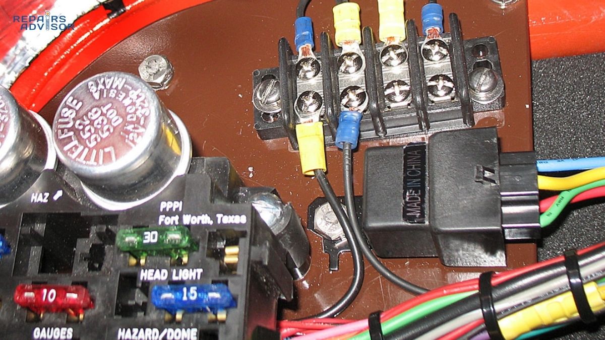
VVT solenoids are generally mounted on the cylinder head in easily accessible locations, often on the front or side of the engine where electrical connections and oil supply lines can be easily routed. These solenoids typically mount with one or two bolts and feature electrical connectors that can be accessed without major disassembly. However, proper diagnosis often requires specialized scan tools capable of commanding VVT solenoid operation and monitoring real-time timing data – equipment typically found in professional shops rather than home garages.
The oil supply system for VVT components includes passages machined into the cylinder head and camshafts themselves, making these internal pathways inaccessible without major engine disassembly. Oil filters and regular oil changes are critical for VVT system health, as contaminated oil can clog the small passages and precise clearances within cam phasers. Many VVT systems also incorporate oil flow control valves and check valves that may be integrated into the cylinder head casting.
For diagnostic purposes, VVT system monitoring typically requires OBD-II scan tools capable of displaying live data streams and performing actuator tests. Professional-grade diagnostic equipment can command specific timing positions and monitor system response, enabling technicians to verify proper operation without engine disassembly. Diagnostic trouble codes related to VVT systems often indicate specific component failures or performance issues that can guide repair decisions.
Safety Considerations: Working on VVT systems requires understanding of engine timing principles and proper tools for camshaft positioning. Incorrect timing installation can cause severe engine damage including valve-to-piston contact. Professional consultation is strongly recommended for cam phaser replacement or any timing-related repairs, especially on interference engines where timing errors can result in catastrophic internal damage.
Skill Level Assessment: Basic VVT maintenance like solenoid replacement is within the capabilities of intermediate DIY enthusiasts with proper tools and service information. However, cam phaser replacement, timing chain work, or internal engine timing adjustments require professional-level expertise, specialized tools, and comprehensive understanding of engine timing relationships. Always consult manufacturer service procedures and timing specifications before attempting any VVT system repairs.
This information is provided for educational reference only. Always consult manufacturer specifications and professional guidance for repair procedures. Safety-critical timing system work should be performed by qualified technicians with proper equipment and training.