Why Fuel Injector Hydraulics Is Critical for Engine Performance
Fuel injector hydraulics represent the heart of modern engine performance, controlling the precise metering and atomization of fuel that directly determines combustion efficiency, power output, and emissions compliance. The hydraulic circuits within fuel injectors operate under extreme pressures—up to 2,000 bar in direct injection systems—using precision engineering to deliver fuel quantities measured in milliseconds and microliters. This needle valve precision enables engines to achieve optimal air-fuel ratios across all operating conditions, from idle stability to full-power acceleration.
When fuel injector hydraulics function correctly, engines produce smooth power delivery, meet stringent emissions standards, and achieve maximum fuel economy. However, hydraulic circuit failures can cause rough idle, misfiring, reduced power, and increased emissions. The spray patterns generated by properly functioning hydraulic systems ensure complete fuel atomization, promoting efficient combustion and reducing carbon deposits.
Key Component Facts:
- Function: Precision fuel metering through hydraulic pressure control
- Operating Pressure: 35-2,000 bar depending on injection system type
- Response Time: 1-5 milliseconds for complete injection cycle
- Failure Impact: Engine performance degradation, emissions non-compliance
Safety Note: Fuel injector service involves high-pressure fuel systems. Always depressurize fuel systems properly and wear appropriate safety equipment when working with injection components.
Fuel Injector Hydraulics Parts and Construction Explained
Modern fuel injector hydraulics rely on precision-manufactured components working in perfect synchronization to control fuel delivery. The needle valve assembly forms the core metering element, featuring a tapered needle that seats against a precision-ground valve seat with tolerances measured in micrometers. This assembly must withstand thousands of operating cycles per minute while maintaining perfect sealing when closed.
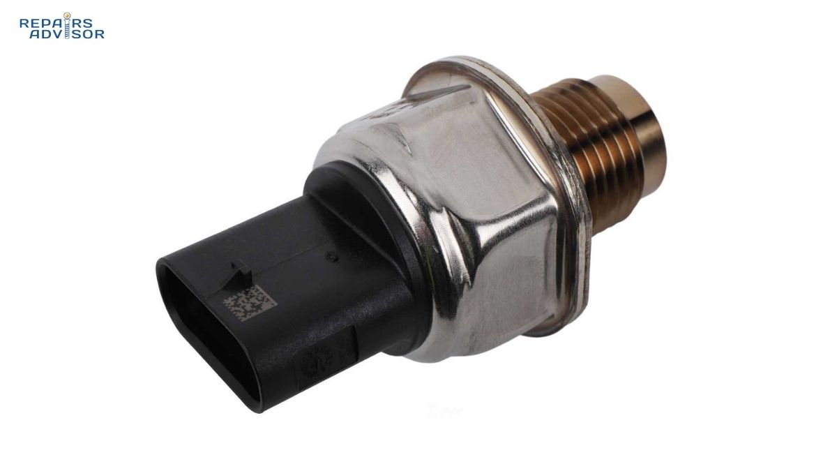
The control chamber represents the hydraulic brain of the injector, utilizing fuel pressure differentials to control needle valve movement. High-pressure fuel fills this chamber, creating the hydraulic force necessary to hold the needle valve closed against combustion chamber pressure. When the ECU signals injection, a solenoid actuator opens a small drain valve, reducing control chamber pressure and allowing fuel rail pressure to lift the needle valve.
Supporting the primary hydraulic circuit are precision-manufactured spring assemblies that provide return force for the needle valve, ensuring rapid closing when injection ends. The injector body houses multiple hydraulic passages, each machined to exacting specifications to maintain consistent flow characteristics. O-ring seals and metal gaskets prevent fuel leakage while withstanding thermal cycling from -40°C to 150°C.
Quality variations between OEM, performance, and aftermarket injectors primarily involve manufacturing tolerances and materials. OEM injectors feature the tightest tolerances for emissions compliance, while performance injectors may offer higher flow rates for modified applications. Budget alternatives often use less precise manufacturing, potentially affecting spray patterns and long-term reliability.
How Fuel Injector Hydraulics Works: Step-by-Step Operation
Step 1: Hydraulic Equilibrium Setup During the closed state, high-pressure fuel from the fuel rail fills both the control chamber above the needle valve and the pressure chamber below. The control chamber’s larger effective area creates net downward hydraulic force, keeping the needle valve seated against the valve seat. This hydraulic balance system ensures positive closure even against combustion chamber pressure spikes reaching 100+ bar.
Step 2: Injection Initiation and Pressure Release When the engine management system signals injection, the solenoid actuator energizes, opening the control valve and allowing fuel to drain from the control chamber back to the fuel tank through the return circuit. This pressure reduction disrupts the hydraulic equilibrium, causing the higher pressure in the main fuel chamber to overcome the reduced control chamber force and lift the needle valve.
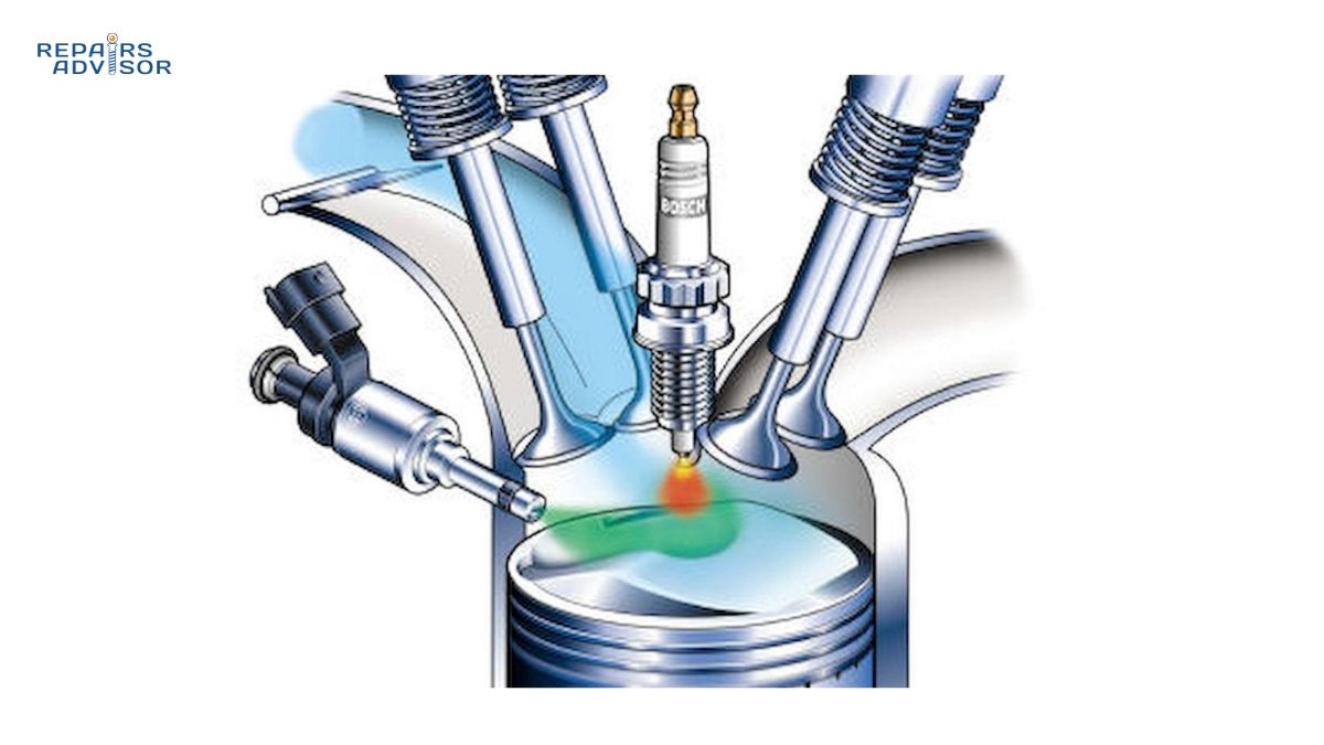
Step 3: Fuel Atomization and Spray Pattern Generation As the needle valve lifts, pressurized fuel flows through precision-ground spray holes or a single orifice, depending on injector design. The high-pressure differential across these orifices—typically 3-4 bar for port injection, up to 200 bar for direct injection systems—creates turbulent flow that atomizes fuel into microscopic droplets. The spray patterns are engineered to match specific engine requirements, from wide-angle conical patterns for port injection to narrow, targeted patterns for direct injection applications.
The hydraulic circuits continuously adapt to varying operating conditions through precise ECU control of injection timing and duration. Temperature compensation adjusts for fuel viscosity changes, while load-based mapping optimizes spray characteristics for different engine demands. This real-time hydraulic modulation enables modern engines to achieve both performance and efficiency targets while maintaining emissions compliance.
Fuel Injector Hydraulics Location and Access Guide
Intermediate DIY Level: Fuel injector access varies significantly between engine designs, requiring different skill levels and safety precautions. Port fuel injectors typically mount in the intake manifold and connect to the fuel rail system, making them relatively accessible for inspection and replacement. However, direct injection injectors mount directly in the cylinder head, often requiring intake manifold removal for access.
Professional Level: Direct injection systems operate under extremely high pressures that can cause serious injury. These systems require specialized tools for pressure relief and injector removal. The hydraulic connections involve high-pressure fuel lines that must be properly supported during service to prevent damage to precision fittings.
Access Preparation Requirements:
- Fuel system depressurization using manufacturer-specified procedures
- Engine bay cleaning to prevent contamination of hydraulic circuits
- Proper torque specifications for hydraulic fittings (typically 15-25 Nm)
- Fuel system pressure testing equipment for post-service verification
Component Locations by Vehicle Type:
- Port Injection: Fuel rail mounted on intake manifold, injectors accessible with basic tools
- Direct Injection: Injectors mounted in cylinder head, often under intake manifold or ignition coils
- Dual Injection: Both port and direct injectors present, requiring careful system identification
Safety-Critical Warnings: High-pressure fuel systems can inject fuel through skin, causing serious medical emergencies. Always use proper pressure relief procedures and never attempt to stop fuel leaks with hands or body parts. Fuel vapors are explosive—ensure adequate ventilation and eliminate ignition sources during service.
Professional Consultation Recommended: For diagnostic testing of hydraulic circuits, injector flow testing, and any work involving fuel system modifications. Modern injection systems integrate with multiple vehicle networks and require scan tool access for proper testing and calibration.
Related Technical Resources:
- How Fuel Injection Systems Work – Complete system overview
- How Direct Injection Systems Work – High-pressure applications
- How Engine Management Systems Work – ECU control integration
- How Fuel Pumps Work – System pressure generation
- Toyota Fuel System Manuals – Brand-specific procedures
- Ford Fuel System Manuals – EcoBoost direct injection systems
- Honda Fuel System Manuals – VTEC fuel delivery integration
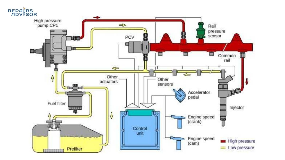
- How Diesel Fuel Systems Work – Common rail hydraulics
Information provided for educational reference only. Fuel injector service requires specialized knowledge and safety equipment. Always consult manufacturer specifications and consider professional assistance for diagnostic testing and hydraulic system service. No warranty implied for repair outcomes.