Modern vehicles come equipped with sophisticated electronic safety systems designed to keep you in control during challenging driving conditions. Among these critical systems, traction control stands out as one of the most important innovations in automotive safety technology. Since becoming mandatory on all new vehicles sold in the United States in 2012, traction control has prevented countless accidents by automatically managing wheel slip during acceleration.
Traction control, often abbreviated as TCS (Traction Control System), works silently in the background of your daily driving, activating only when it detects that one or more of your drive wheels is losing grip on the road surface. Whether you’re accelerating from a stoplight on rain-soaked pavement, navigating an icy parking lot, or simply giving your vehicle too much throttle on a loose gravel surface, your traction control system constantly monitors your wheels and intervenes when necessary to maintain your vehicle’s stability and forward momentum.
Understanding how traction control works empowers you to recognize when the system is functioning normally, identify potential problems, and make informed decisions about when the rare situation arises that requires temporarily disabling the system. This comprehensive guide explores the technology behind traction control, explaining how sensors, hydraulic brakes, and engine management systems work together to prevent wheel spin and keep your vehicle under control.
Throughout this article, we’ll examine the major components that make traction control possible, walk through the step-by-step process of how the system detects and corrects wheel slip, explore advanced features found in modern systems, and provide guidance on maintenance and troubleshooting. We’ll also clarify the important distinctions between traction control and related systems like ABS (Anti-lock Braking System) and electronic stability control, which work together as an integrated safety ecosystem in your vehicle.
What is Traction Control?
At its most fundamental level, traction control is a vehicle safety system designed to prevent your drive wheels from spinning faster than the road surface can accommodate. When a wheel loses traction—meaning the tire can no longer maintain adequate grip on the road—it begins to spin freely rather than propelling the vehicle forward. This wheel slip reduces your ability to accelerate effectively and, more critically, can lead to a loss of directional control that puts you at risk of an accident.
Traction control automatically detects this wheel slip condition and takes corrective action to restore traction. The system accomplishes this through two primary methods: applying braking force to the spinning wheel and reducing engine power delivery. By slowing down the wheel that’s losing traction, the system allows the tire to regain grip on the road surface. Simultaneously, in many cases, the system reduces the engine’s power output to prevent overwhelming the available traction. These interventions happen automatically and extremely quickly—often within milliseconds of detecting the problem—without requiring any input from the driver.
When and Why TCS Activates
Your traction control system springs into action in a variety of real-world driving scenarios. The most common activation occurs when accelerating on wet pavement. When roads are slick from rain, the coefficient of friction between your tires and the road surface drops dramatically. Without traction control, aggressive acceleration could cause your drive wheels to spin uselessly, converting engine power into wheel rotation rather than forward motion. The system detects this spinning and intervenes to maintain forward progress.
Winter driving presents another frequent scenario for traction control activation. Snow and ice create extremely low-traction surfaces where even gentle throttle application can cause wheel slip. Your traction control system becomes particularly valuable here, helping you maintain mobility and control on treacherous winter roads. Similarly, loose surfaces like gravel, sand, or mud challenge your tires’ ability to grip, and traction control helps manage power delivery to maximize whatever limited traction is available.
Even in dry conditions, traction control can activate if you accelerate too aggressively, particularly in high-powered vehicles or when making turns under acceleration. The lateral forces generated during cornering reduce the amount of grip available for acceleration, and traction control helps prevent loss of control in these dynamic situations.
Without traction control, wheel spin creates several dangerous situations. In front-wheel-drive vehicles, spinning front wheels mean you lose both propulsion and steering control simultaneously. In rear-wheel-drive vehicles, excessive rear wheel spin can cause the back end to step out unexpectedly, inducing oversteer that can result in a spin. All-wheel-drive vehicles aren’t immune either—uncontrolled wheel spin wastes energy, reduces forward momentum, and can still lead to instability depending on which wheels lose traction.
TCS vs. ABS vs. ESC: Understanding the Differences
Modern vehicles integrate multiple electronic safety systems that work together but serve distinct purposes. Understanding these differences helps you appreciate how your vehicle’s complete safety architecture functions.
Traction control specifically addresses wheel slip during acceleration. When you press the throttle and your drive wheels begin to spin faster than the vehicle’s actual speed would indicate, TCS intervenes. The system’s sole focus is maintaining traction when you’re trying to speed up or maintain speed under acceleration.
Anti-lock braking systems (ABS) tackle the opposite problem—wheel lockup during braking. When you brake hard and a wheel stops rotating completely while the vehicle is still moving, that locked wheel loses steering capability and can cause skidding. ABS rapidly pulses the brakes to prevent wheel lockup, allowing you to maintain steering control during emergency stops.
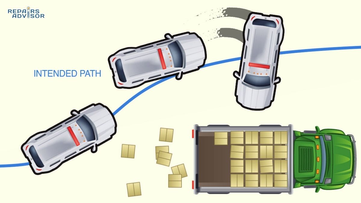
Electronic stability control (ESC) operates during cornering and maneuvering. This system monitors your vehicle’s actual path versus where you’re trying to steer. If it detects understeer (front end pushing wide) or oversteer (rear end stepping out), ESC applies individual wheel brakes and adjusts engine power to help bring your vehicle back to your intended path.
These three systems share many components—particularly wheel speed sensors and hydraulic brake system elements—and communicate constantly through your vehicle’s electronic network. This integrated approach provides comprehensive protection across all driving situations: accelerating, braking, and cornering. The systems work so seamlessly together that you might never notice when one activates, though you’ll likely see a warning light flash on your dashboard when intervention occurs.
Major Components of Traction Control Systems
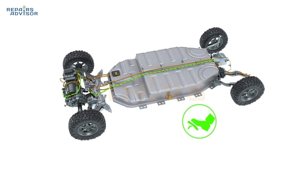
Understanding the hardware that makes traction control possible reveals the sophisticated engineering behind this life-saving technology. Modern traction control systems integrate multiple sensors, control units, and actuators working in concert to detect and correct wheel slip in real time.
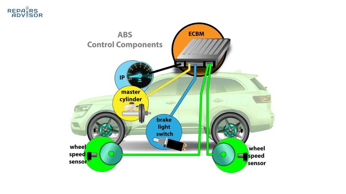
Wheel Speed Sensors
The foundation of any traction control system is the ability to accurately measure how fast each wheel is rotating. Wheel speed sensors, mounted at all four corners of your vehicle, continuously monitor the rotational speed of each wheel and transmit this information to the control system.
These sensors come in two primary technology types. Magnetic reluctance sensors, also called passive sensors, use a magnetic pickup coil positioned near a toothed wheel (tone ring or reluctor ring) that rotates with the wheel. As the teeth pass the sensor, they disturb the magnetic field, generating an alternating current signal whose frequency corresponds to wheel speed. Hall effect sensors, the active type, use semiconductor technology to detect the passing of magnetic fields and produce a cleaner digital signal that works better at low speeds, including when the vehicle is stationary.
The sensors mount in close proximity to the tone ring, which is either integrated into the wheel bearing assembly or attached to the axle shaft. This positioning exposes the sensors to harsh environmental conditions—road spray, salt, debris, extreme temperatures, and vibration—making them one of the more vulnerable components in the traction control system. The typical air gap between the sensor and tone ring measures just 0.020 to 0.050 inches, and contamination or damage to either component can disrupt signal quality.
When functioning properly, wheel speed sensors generate frequency-based signals that increase proportionally with wheel speed. The traction control ECU monitors these signals constantly, comparing the rotational speeds of all four wheels many times per second. Since these same sensors serve the ABS system and often provide input to electronic stability control, a single sensor failure can disable multiple safety systems simultaneously.
Electronic Control Unit (ECU)
The brain of your traction control system is a dedicated electronic control unit, often integrated with the ABS control module due to the shared functionality between these systems. This sophisticated computer receives input from multiple sensors throughout the vehicle and makes split-second decisions about when and how to intervene.
The ECU’s processing capabilities are impressive. It receives wheel speed data from all four sensors simultaneously, comparing individual wheel speeds to detect discrepancies that indicate wheel slip. Typically, if one drive wheel is spinning 20-30% faster than the non-drive wheels or the other drive wheel, the ECU recognizes this as a traction loss event requiring intervention. However, the decision-making process is far more nuanced than simply comparing raw wheel speeds.
The ECU also considers throttle position to understand driver intent, vehicle speed to establish baseline expectations, and steering angle to account for normal speed differences between inside and outside wheels during turns. Some advanced systems incorporate lateral acceleration sensors and yaw rate sensors (measuring vehicle rotation) to better understand dynamic driving situations.
Modern traction control ECUs employ sophisticated algorithms that evaluate not just whether wheel slip is occurring, but also its severity, duration, and rate of change. These algorithms determine the appropriate intervention strategy—whether to apply brakes, reduce engine power, or use a combination of both approaches. The system must balance multiple objectives: restore traction quickly, minimize driver perception of the intervention, maintain forward momentum when possible, and prevent overcorrection that could cause different problems.
The ECU communicates with other vehicle systems through the CAN (Controller Area Network) bus, exchanging data with the engine control module, transmission control unit, and other systems. This network integration allows traction control to coordinate its actions with other vehicle systems for optimal performance.
Hydraulic Brake System Integration
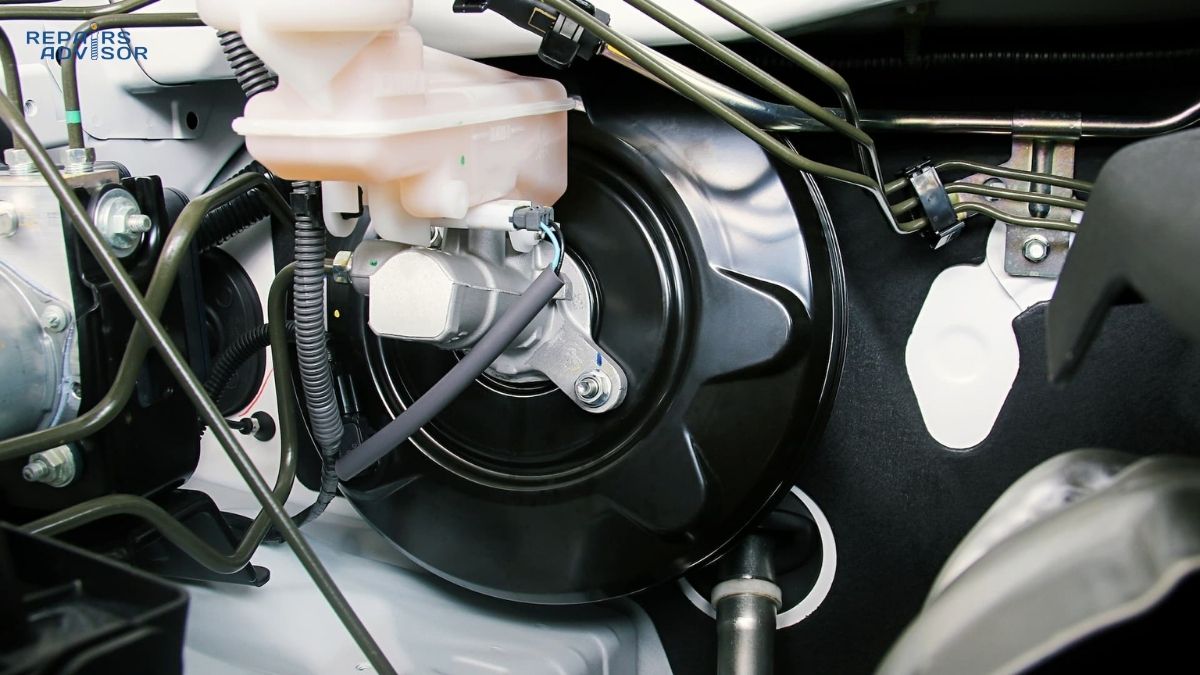
When your traction control system decides that brake intervention is necessary to slow a spinning wheel, it relies on hydraulic components shared with your ABS system. The ABS hydraulic modulator—a compact unit typically mounted in the engine compartment near the brake master cylinder—contains the valves, pump, and accumulator needed for both systems to function.
Inside the modulator, precision solenoid valves control hydraulic pressure to each wheel independently. When the ECU commands brake application to a spinning wheel, it energizes specific solenoid valves that route pressurized brake fluid to that wheel’s brake caliper. For traction control operation, the system must be capable of generating brake pressure independent of driver pedal input, since TCS activates during acceleration, not braking.
An electric hydraulic pump provides this pressure-generation capability. When traction control needs to apply brakes, the pump pulls fluid from the brake reservoir and pressurizes it to levels sufficient for effective wheel braking—typically 1,000-2,000 PSI or more. A high-pressure accumulator stores this pressurized fluid, ensuring immediate availability when the system needs to respond to wheel slip. This accumulator also helps provide the rapid pressure modulation needed for precise traction control.
The response time of modern hydraulic systems is remarkably fast. From the moment the ECU detects wheel slip to actual brake application can take as little as 50-100 milliseconds. This quick reaction prevents excessive wheel spin from developing and minimizes the disruption to your driving experience. You might feel a slight vibration or hear a brief buzzing sound when the system activates—this is the hydraulic pump and valves operating, and it’s completely normal.
Engine and Powertrain Control Interface
While brake intervention forms the primary method of traction control, reducing engine power provides an important supplemental or alternative approach to managing wheel slip. The traction control ECU communicates directly with your engine control module to command power reduction when needed.
In modern vehicles equipped with electronic throttle control (drive-by-wire), the system can directly close the throttle plate to restrict airflow into the engine, regardless of accelerator pedal position. This provides instantaneous power reduction with no mechanical delay. Simultaneously or alternatively, the system can reduce fuel injection by shortening the pulse width sent to the fuel injectors, decreasing the amount of fuel entering the combustion chambers.
Ignition timing retardation offers another power reduction method. By delaying the spark timing, the engine produces less torque even with the same amount of fuel and air. In turbocharged engines, the system may also command the wastegate to open, reducing boost pressure and consequently engine output. Some high-performance applications even employ cylinder deactivation during severe traction control events, temporarily shutting down one or more cylinders to dramatically reduce power.
The transmission control system may also participate in traction management. In vehicles with automatic transmissions, the system might command a shift to a higher gear to reduce the torque multiplication reaching the drive wheels, making it easier to maintain traction. Some advanced systems can even modulate torque converter lockup to help manage power delivery.
These engine and transmission interventions typically last only a fraction of a second to a few seconds, depending on how quickly traction is restored. Drivers usually perceive this as a momentary hesitation or slight stumble in acceleration—a small price to pay for maintaining vehicle control. The system is programmed to minimize these interventions’ intrusiveness while still providing effective traction management.
How Traction Control Works: Step-by-Step Operation
Understanding the complete operational cycle of traction control reveals the sophisticated coordination between sensors, computers, and mechanical systems that happens automatically every time you drive. Let’s walk through exactly what occurs from the moment you start your vehicle to when the system intervenes during a traction loss event.
Step 1: Continuous Monitoring (Normal Driving)
From the instant you start your vehicle, your traction control system begins operating in monitoring mode. The wheel speed sensors at each corner generate continuous signal streams as the wheels rotate. These sensors produce frequency-based signals—essentially, an alternating current that pulses faster as wheel speed increases. The tone ring mounted at each wheel has a specific number of teeth (commonly 48 or 100), and each tooth passing the sensor generates one pulse.
The ECU processes these signals in real time, calculating the actual rotational speed of each wheel. In modern systems, this processing occurs 50 to 100 times per second or even faster, providing essentially continuous wheel speed data. The ECU establishes a baseline comparison between all four wheels, accounting for normal variations that occur during turns when inside wheels naturally rotate slower than outside wheels.
During this monitoring phase, the system remains dormant from the driver’s perspective. No lights illuminate on the dashboard (beyond the brief self-check when you first start the vehicle), no interventions occur, and you’re completely unaware of the system’s vigilant operation. The ECU is simply watching and waiting, ready to act within milliseconds if it detects the characteristic signature of wheel slip.
Step 2: Wheel Slip Detection
Wheel slip detection is where the system’s sophisticated algorithms come into play. The ECU doesn’t simply look for one wheel spinning faster than the others—it must distinguish between normal driving situations and true traction loss events requiring intervention.
The primary detection criterion is a speed differential between drive wheels and non-drive wheels, or between the two drive wheels themselves. When one drive wheel begins spinning significantly faster than the others—typically 20-30% faster, though this threshold varies by system and driving conditions—the ECU flags this as potential wheel slip. However, the system must also consider how long this condition persists and how rapidly it develops. A brief speed spike during a normal shift might not trigger intervention, but sustained or rapidly increasing wheel speed differential will.
The ECU cross-references this wheel speed data with other inputs to confirm the wheel slip diagnosis. Throttle position tells the system how much power the driver is requesting. If throttle position is high and one wheel is spinning much faster than the others, this strongly suggests traction loss. Vehicle speed from the non-drive wheels provides a baseline for expected drive wheel speeds. Steering angle input accounts for normal speed differences during turns—the outside wheels travel farther and rotate faster than inside wheels in a turn, and the system must distinguish this from actual wheel slip.
Some advanced systems also consider factors like ambient temperature (which affects tire grip), windshield wiper usage (indicating wet conditions), and even historical data about surface conditions based on sensor inputs. This comprehensive analysis allows the system to minimize false activations while quickly responding to genuine traction loss events.
Step 3: Intervention Strategy Selection
Once the ECU confirms that wheel slip is occurring and intervention is warranted, it must select the appropriate response strategy. This decision-making process considers the severity of the slip, the driving situation, and the desired outcome.
For mild wheel slip—perhaps just a momentary chirp when accelerating from a stoplight—brake intervention alone might suffice. The system applies a small amount of braking pressure to the slipping wheel, just enough to slow it down and allow the tire to regain grip. This approach is nearly imperceptible to the driver and maintains smooth forward acceleration.
Moderate wheel slip situations might warrant engine power reduction instead of or in addition to brake intervention. If one wheel is spinning significantly but applying brakes might be too disruptive, the system can reduce engine torque output to bring wheel speeds back into alignment. This is particularly common during sustained acceleration on moderately slippery surfaces.
Severe wheel slip events—such as flooring the throttle on glare ice—demand aggressive intervention using both brake application and substantial engine power reduction. The system might apply full brake pressure to the spinning wheel while simultaneously cutting engine power by 50% or more. These dramatic interventions are necessary to quickly regain control and prevent the vehicle from becoming unstable.
The system prioritizes several objectives when selecting its strategy: restore traction as quickly as possible to maintain vehicle control, minimize driver awareness of the intervention to avoid startling or confusing the driver, maintain forward momentum whenever safe to do so rather than bringing the vehicle to a stop, and prevent overcorrection that could cause a different traction problem on the opposite wheel.
Step 4: Brake Application (Primary Method)
When the ECU decides brake intervention is necessary, it commands the ABS hydraulic modulator to pressurize the brake circuit leading to the slipping wheel’s brake caliper. The electric hydraulic pump activates, drawing brake fluid from the reservoir and pressurizing it. Solenoid valves open the appropriate pathways to route this pressurized fluid to the specific wheel that needs braking.
As hydraulic pressure builds in the caliper, the brake piston extends, pressing the brake pads against the brake rotor. This creates friction that slows the spinning wheel. The amount of brake pressure applied varies based on the severity of the wheel slip—light pressure for minor slip, heavy pressure for severe spinning.
The genius of brake-based traction control lies in how it interacts with your vehicle’s differential. In a conventional open differential (the most common type), torque naturally flows to the path of least resistance—the wheel that’s spinning freely. By applying brakes to that spinning wheel, the system increases resistance on that side. The differential responds by redirecting torque to the opposite wheel, which presumably has better traction. This effectively turns your open differential into a limited-slip differential through electronic control.
The brake application is rarely constant. The system typically pulses the brakes on and off rapidly, applying pressure for brief intervals and then releasing to reassess the situation. This prevents overheating the brake components and allows for more precise control of wheel speed. You might feel this pulsing as a vibration through the floor or hear a rapid buzzing or clicking sound from under the vehicle when traction control is actively working.
Step 5: Engine Power Reduction (Secondary/Supplemental)
Simultaneously with or as an alternative to brake intervention, the traction control system can command engine power reduction. This approach becomes particularly important when brake intervention alone isn’t sufficient or when sustained intervention might overheat the brake system.
In vehicles with electronic throttle control, the ECU can directly command the throttle to close partially or completely, overriding your accelerator pedal input. This immediately reduces the amount of air entering the engine, which correspondingly reduces power output. You’ll perceive this as a sudden loss of acceleration or a feeling that the engine isn’t responding to your throttle input.
Fuel delivery reduction provides another power management method. The engine control module, responding to commands from the traction control ECU, reduces the pulse width sent to the fuel injectors. Shorter injector pulses mean less fuel enters the combustion chambers, producing less power. This can be modulated very precisely, reducing power by exactly the amount needed to restore traction.
Ignition timing retardation delays when the spark plugs fire relative to piston position. By sparking later in the compression stroke, the engine produces less torque even with the same air-fuel mixture. This method is particularly effective because it can be implemented rapidly and doesn’t affect engine smoothness as dramatically as cutting fuel.
In turbocharged engines, the traction control system might command the wastegate valve to open, allowing exhaust gases to bypass the turbocharger. This reduces boost pressure, which in turn reduces engine power output. High-performance applications might even temporarily deactivate one or more cylinders by cutting fuel and spark to those cylinders, dramatically reducing power.
The duration of these power reduction interventions varies based on conditions. In many cases, power is reduced for just 100-500 milliseconds—brief enough that you barely notice, but long enough to restore traction. In more sustained slippery conditions, power might be reduced for several seconds while the system works to maintain the delicate balance between available traction and power delivery.
Step 6: Traction Restoration and System Reset
As the brake and/or engine power interventions take effect, wheel speeds begin to come back into alignment. The previously spinning wheel slows down as brakes are applied and engine power is reduced. Meanwhile, the opposite wheel (or wheels) that had traction can now receive more torque through the differential action, helping propel the vehicle forward.
The ECU continuously monitors the results of its interventions through the wheel speed sensors. As soon as it detects that the slipping wheel has returned to a speed consistent with the vehicle’s actual velocity, the system begins releasing brake pressure. The solenoid valves close the pressurized pathways and open return routes, allowing brake fluid to flow back to the reservoir. The brake caliper piston retracts slightly, releasing pressure on the pads and allowing the wheel to rotate freely again.
Similarly, engine power returns to match your accelerator pedal position. The electronic throttle reopens, fuel injection returns to normal pulse widths, and ignition timing advances back to optimal settings. In turbocharged engines, the wastegate closes to restore boost pressure. The transition back to normal power delivery is usually smooth and progressive rather than abrupt.
The system then returns to its monitoring mode, watching wheel speeds continuously for any signs that intervention might be needed again. In severe conditions—such as accelerating on glare ice—the system might cycle through this intervention process 5 to 10 times per second or even more frequently. Each cycle involves detecting slip, applying intervention, checking results, and adjusting the response. This rapid cycling is what creates the characteristic pulsing sensation and buzzing sound when traction control is working hard.
The traction control warning light on your dashboard flashes whenever the system is actively intervening. This provides visual feedback that the system is working to maintain traction. Once the slippery condition passes and normal traction returns, the warning light extinguishes, and the system continues its silent monitoring.
Advanced Traction Control Features
As automotive technology has evolved, so too have traction control systems. Modern vehicles—particularly performance-oriented and luxury models—often include sophisticated enhancements that go well beyond basic wheel slip prevention. These advanced features adapt traction control behavior to different driving situations and integrate with other vehicle systems for improved performance and capability.
Performance-Oriented Systems
High-performance vehicles face a unique challenge: providing maximum acceleration capability while still offering protection against loss of control. To address this, many performance cars offer multiple traction control modes that adjust the system’s intervention thresholds and strategies.
Sport mode settings typically allow more wheel slip before intervening. Instead of activating at 20% slip, the system might wait until 40% or more. This permits controlled tire slip that can actually improve acceleration in some situations—particularly during launches where some wheel spin helps maximize traction at the tire’s optimal slip angle. Performance drivers appreciate this flexibility because it allows them to extract maximum acceleration while still providing a safety net if conditions deteriorate or technique falters.
Launch control systems integrate traction management with engine RPM and clutch (or torque converter) control to achieve maximum acceleration from a standing start. When activated, these systems hold engine RPM at an optimal launch speed, then carefully modulate power delivery and wheel slip as you release the brake or engage the clutch. The result is consistently quick, controlled launches that maximize available traction without overwhelming it.
Some high-performance systems can simulate an electronic limited-slip differential function. By individually braking wheels that are losing traction and allowing more power to flow to wheels with grip, the system mimics the behavior of a mechanical limited-slip differential but with more precision and adaptability. This is particularly valuable in all-wheel-drive performance vehicles where torque can be distributed among all four wheels.
Track-focused vehicles might offer a complete traction control disable mode for use on closed courses. However, even in these systems, a threshold intervention often remains—if wheel slip becomes truly dangerous (such as spinning completely out of control), the system will intervene regardless of driver preference. This provides experienced drivers the freedom they want while still offering ultimate protection in extreme situations.
All-Wheel Drive (AWD) Integration
Traction control systems in all-wheel-drive vehicles have additional complexity and capability compared to two-wheel-drive systems. These systems can manage power distribution among all four wheels, providing exceptional traction and control in challenging conditions.
In vehicles with active AWD systems featuring electronically controlled coupling devices, traction control works closely with the transfer case or center differential. When the system detects wheel slip at the front or rear axle, it can command the AWD coupling to engage or disengage, sending more or less power to that axle as conditions demand. This dynamic power distribution happens continuously as you drive, often without your awareness.
The sophistication of four-wheel traction control becomes apparent in off-road situations. When one wheel encounters a slippery surface—such as hitting a patch of ice or lifting off the ground over uneven terrain—the system can brake that individual wheel while allowing power to continue flowing to the other three wheels that maintain traction. This effectively turns an open differential system into a virtual locker, providing capability that approaches mechanically locked differentials without their downsides.
Hill descent control systems, found in many AWD and 4WD vehicles, use traction control technology to maintain a slow, controlled descent on steep grades. The system automatically applies individual wheel brakes to prevent acceleration and maintain a steady, safe speed without driver intervention. This is particularly valuable when descending slippery slopes where loss of control could be dangerous.
Off-road driving modes reprogram traction control behavior for loose surfaces. In sand mode, for example, the system allows more wheel spin because some slip is necessary to maintain momentum and “float” on top of loose sand. Rock crawl modes minimize intervention to allow wheels to climb over obstacles without fighting the system. These specialized calibrations recognize that the optimal traction control strategy varies dramatically depending on surface conditions.
Predictive and Adaptive Systems
The latest generation of traction control systems incorporates predictive and adaptive capabilities that enhance performance beyond simple reactive intervention. These systems learn from driving patterns, predict conditions based on multiple inputs, and adjust their behavior accordingly.
Weather-aware calibration represents one form of predictive capability. By monitoring ambient temperature through exterior temperature sensors, the system recognizes when conditions are likely to be slippery. Below freezing, for example, the system might adopt more conservative intervention thresholds, activating sooner and more aggressively than it would in warm, dry conditions. Some systems even monitor windshield wiper usage as an indicator of wet conditions, adjusting traction control sensitivity accordingly.
Integration with adaptive cruise control and other advanced driver assistance systems allows for sophisticated predictive behavior. If the radar and camera systems detect that traffic ahead is slowing or that the vehicle ahead is equipped with active brake lights, your traction control system might pre-emptively reduce power delivery in preparation for the braking and potential traction loss that might follow.
Some premium vehicles incorporate surface recognition systems that use existing sensors—including wheel speed sensors, suspension position sensors, and even audio-frequency analysis of tire noise—to identify road surface types. The system can distinguish between dry asphalt, wet pavement, snow, ice, gravel, and other surfaces, then adjust traction control parameters to match the detected conditions. This happens continuously and automatically as you drive.
Driver style adaptation represents another advancement. The system learns how aggressively you typically drive by monitoring your throttle application patterns, cornering speeds, and other behaviors. Conservative drivers receive earlier, gentler interventions, while more spirited drivers might experience slightly higher slip thresholds and less intrusive interventions. The system essentially tailors its behavior to match your driving style while still maintaining safety margins.
These advanced features work largely invisibly, enhancing your driving experience and safety without requiring your attention or configuration. The traction control system has evolved from a simple wheel slip prevention mechanism into an intelligent system that actively anticipates and adapts to conditions, providing sophisticated protection with minimal intrusion.
The TCS Warning Light and Dashboard Indicators
Your vehicle communicates the status of its traction control system through dashboard warning lights and, in some cases, messages on the information display. Understanding what these indicators mean helps you distinguish between normal system operation and potential problems requiring attention.
Normal TCS Light Behavior
The traction control warning light typically appears as an icon showing a car with wavy or squiggly lines behind it, suggesting a vehicle sliding or losing traction. When you first start your vehicle, this light should illuminate briefly—usually for just two to three seconds—as part of the system’s self-check sequence. The system performs diagnostics, verifying that all sensors are responding and that the control module can communicate with other vehicle systems. If everything checks out, the light extinguishes, and you can drive with confidence that traction control is ready to protect you.
During driving, a flashing or blinking traction control light indicates that the system is actively working to manage wheel slip. This is completely normal and expected when you’re driving in slippery conditions or accelerating enthusiastically. The flashing light serves as feedback that the system detected wheel slip and is intervening to restore traction. You might simultaneously hear a buzzing or whirring sound from the ABS hydraulic pump operating, or feel a slight pulsing sensation through the floor or steering wheel.
When the traction control light flashes, it’s actually a good sign—it means the system is functioning exactly as designed, automatically protecting you from loss of traction. The light will stop flashing once traction is restored and normal driving conditions return. These activation events are particularly common during winter driving, when accelerating from stops on wet pavement, or when driving on loose gravel or sand.
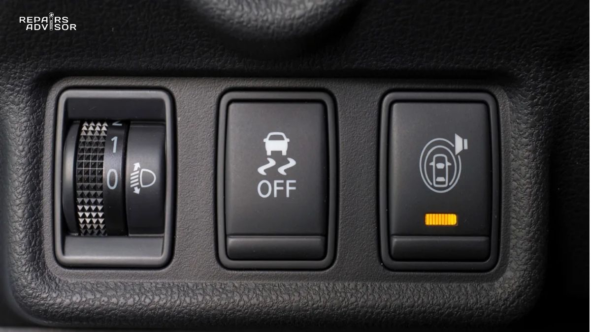
TCS Off Indicator
Many vehicles display a separate indicator when traction control has been manually disabled by the driver. This typically appears as “TCS OFF,” “TC OFF,” or the traction control symbol with the word “OFF” beneath or beside it. Some vehicles use an amber or yellow light, while others may illuminate the symbol in a different color than the standard warning light.
This indicator exists because most vehicles allow drivers to manually turn off traction control using a button or through the vehicle’s menu system. The TCS Off light simply confirms that your input was received and the system is indeed deactivated. This is an important distinction—the light isn’t indicating a problem; it’s confirming the system status you requested.
It’s crucial to remember to re-enable traction control after the situation that required disabling it has passed. The system doesn’t automatically turn itself back on in most vehicles (though some do restore TCS at key-off or when vehicle speed exceeds a certain threshold, typically around 35 mph). Driving with traction control off significantly increases your risk of losing control in slippery conditions, so this indicator serves as a reminder that an important safety system is currently inactive.
Continuous TCS Warning Light
When the traction control warning light remains steadily illuminated rather than flashing, this indicates a problem with the system. A continuous warning light means the traction control system has detected a fault and has disabled itself. Understanding the potential causes helps you determine appropriate next steps.
Wheel speed sensor failures represent the most common cause of traction control warnings. These sensors face harsh environmental conditions—exposure to road spray, salt, debris, extreme temperatures, and constant vibration. Sensor contamination from metal particles attracted to the magnetic sensor element can disrupt the signal. The tone ring (reluctor ring) that the sensor reads can become damaged from road debris or corrosion. Wiring harnesses and connectors, which route through the wheel well area, are susceptible to damage from rocks, water intrusion, and corrosion.
Problems with the ABS hydraulic system also trigger traction control warnings since the systems share components. Low brake fluid level affects both systems’ operation. The hydraulic pump or pressure accumulator can fail, preventing the system from generating the pressure needed for brake intervention. Solenoid valve malfunctions prevent proper control of brake pressure to individual wheels.
ECU and electrical issues represent another category of problems. The ABS/TCS control module itself can fail, though this is less common than sensor problems. Communication errors on the vehicle’s CAN bus network can prevent the traction control system from exchanging data with other systems. Poor ground connections in the electrical system can cause erratic sensor signals or control module malfunctions.
When the traction control warning light stays on, proper diagnosis requires specialized equipment. A professional-grade scan tool can read diagnostic trouble codes stored in the system’s memory, identifying which specific component has failed or is providing faulty data. Common diagnostic trouble codes include C0031 for wheel speed sensor circuit problems, and various other codes indicating specific failures.
While a illuminated TCS warning light means traction control is currently disabled, your vehicle remains safe to drive. You simply won’t have the assistance of traction control if you encounter slippery conditions. Your standard braking system continues to function normally, though ABS may also be disabled if the problem affects shared components. You should, however, schedule diagnostic service promptly to restore this important safety feature.
When to Turn OFF Traction Control
Traction control should remain active during virtually all normal driving situations. However, specific scenarios exist where temporarily disabling the system becomes necessary or beneficial. Understanding when and why to turn off traction control—and equally important, when to leave it on—helps you make safe, informed decisions.
Stuck Vehicle Situations (Primary Valid Reason)
The most common legitimate reason to disable traction control occurs when your vehicle becomes stuck in deep snow, mud, or sand. In these situations, the very wheel spin that traction control prevents is actually necessary to free your vehicle.
When stuck in deep snow, your vehicle needs momentum and tire-generated forces to break through the snow and reach more solid ground beneath. A certain amount of wheel spin allows the tires to pack down snow, create a temporary surface, and generate the forces needed to climb out of a rut. With traction control active, the system interprets this wheel spin as a problem and immediately intervenes by reducing power and applying brakes. This intervention prevents you from building the momentum needed to escape.
The “rocking” technique—a proven method for extracting stuck vehicles—requires alternately shifting between forward and reverse gears to build momentum through repetitive motion. Each forward movement compacts the snow or mud slightly, and each reverse movement does the same. With multiple cycles, you can often work the vehicle free. Traction control fights against this technique by preventing the wheel spin that generates the rocking motion.
Similarly, when stuck in mud or sand, you may need sustained wheel spin to “paddle” through the material and find solid ground. In sand particularly, some wheel spin helps the tires float on top of the loose surface rather than digging in. Traction control’s natural response to limit wheel spin works against this needed behavior.
The solution in these stuck situations is to temporarily disable traction control. With the system off, you can apply throttle more aggressively, use the rocking technique effectively, and generate the wheel spin and momentum needed to free your vehicle. Once you’ve successfully extracted your vehicle and returned to more stable driving conditions, immediately re-enable traction control. The system should never remain off longer than absolutely necessary.
Steep Snow-Covered Hill Climbing
Another specific situation where traction control might hinder rather than help involves climbing steep grades from a complete stop when the surface is snow-covered or very slippery. This scenario combines the worst elements: low traction, gravity working against you, and the need for sustained power delivery.
When attempting to climb a steep, slippery hill, momentum becomes critical. You need consistent power delivery to maintain forward progress. However, the slippery surface naturally causes some wheel slip, even under steady throttle. Traction control, detecting this slip, may intervene by reducing power or applying brakes. On a steep grade, this power reduction can rob you of the momentum needed to continue climbing, potentially leaving you stuck on the slope or even sliding backward.
Some vehicles address this with specific driving modes—winter mode, hill ascent mode, or similar features—that adjust traction control behavior for this exact scenario. These modes allow slightly more wheel slip before intervention and use gentler intervention strategies that maintain momentum. If your vehicle offers these modes, using them is far preferable to completely disabling traction control.
However, if no such mode exists and you find yourself unable to climb a steep, snow-covered hill with traction control active, briefly disabling the system might allow you to maintain the momentum needed to reach the top. This should be attempted with caution and only when no alternative route exists. Once you’ve successfully climbed the hill, immediately re-enable traction control.
Tire Chain Usage
Some vehicle manufacturers recommend or require disabling traction control when driving with tire chains installed. The chains create irregular contact with the road surface and can generate vibrations and speed variations that confuse the wheel speed sensors. The system might interpret the chains’ noise and vibration as wheel slip, leading to unnecessary interventions that disrupt smooth driving.
However, this guidance varies by manufacturer. Some newer vehicles have calibrations specifically designed to work correctly with tire chains installed. Always consult your vehicle’s owner’s manual for specific guidance regarding chain use and traction control. If the manual doesn’t require disabling TCS with chains, leaving it active provides continued protection even with chains mounted.
When to KEEP TCS On (99% of Driving)
It cannot be overstated: traction control should remain active during virtually all normal driving. The system exists as a critical safety feature, and deactivating it increases your accident risk significantly. Let’s be absolutely clear about situations where traction control should definitely remain on.
All winter driving on public roads requires traction control to remain active. Driving on snow-covered streets, icy intersections, or wet winter roads all benefit from TCS protection. The system helps you maintain control during acceleration and assists with stability in slippery conditions. Some drivers mistakenly believe traction control should be disabled for winter driving, but the opposite is true—winter conditions are precisely when you need this protection most.
Wet weather driving of any kind demands active traction control. Rain-slicked pavement, particularly during the first rain after a dry spell when oils float to the surface, creates treacherous low-traction conditions. Traction control prevents wheel spin during acceleration and helps maintain stability when accelerating out of turns or merging onto highways.
Normal driving in all conditions—dry pavement, highway cruising, city streets—should always occur with traction control enabled. Even in seemingly ideal conditions, unexpected slippery spots can appear (oil spills, antifreeze leaks, wet leaves, manhole covers, painted road markings when wet). Traction control responds instantly to these hidden hazards, often preventing loss of control before you’re even aware a problem existed.
Some vehicles offer a “snow mode” or “winter mode” that adjusts various vehicle parameters including traction control sensitivity, transmission shift points, and throttle response. Using snow mode is NOT the same as turning off traction control. Snow mode keeps TCS active but tunes it for winter conditions with gentler interventions and modified thresholds. This mode should be your first choice for winter driving, maintaining protection while optimizing performance for slippery conditions.
How to Disable TCS (Vehicle-Specific)
If you find yourself in one of the rare situations where disabling traction control becomes necessary, the process varies by vehicle manufacturer and model. Most vehicles provide a button or switch for manual TCS control, though the location and operation differ.
The most common TCS button location is on the center console near the gear shifter, often among other driving mode controls. Some vehicles place it on the lower dashboard to the left of the steering wheel, integrated with other system controls. In some newer vehicles, particularly those with digital displays, TCS control might be buried in a menu system accessed through the infotainment screen rather than having a dedicated physical button.
The button itself typically displays the traction control symbol—a car with wavy lines beneath it—sometimes with the word “OFF” or “TCS” labeled. The procedure for deactivating the system also varies. Many vehicles require a simple press of the button to toggle TCS on or off. Others require holding the button for 3-5 seconds to disable the system, a design choice intended to prevent accidental deactivation. Some vehicles require accessing a menu system and confirming your choice to disable this safety feature.
When successfully disabled, you’ll see the TCS Off indicator illuminate on your dashboard. In many vehicles, particularly those with electronic stability control (ESC) integrated with traction control, a single button press might disable only TCS while ESC remains active. Holding the button longer may disable both systems. Other vehicles have separate controls for TCS and ESC. Understanding your specific vehicle’s configuration is important.
Some vehicles incorporate automatic re-enabling features. Once vehicle speed exceeds approximately 35-40 mph, the system automatically reactivates regardless of the button state. This provides protection at higher speeds where traction control is more critical while allowing disabled operation at low speeds where stuck-vehicle situations occur. Other vehicles keep the system disabled until you manually re-enable it or until the next key cycle when you restart the vehicle.
Always consult your vehicle’s owner’s manual for specific instructions on disabling and re-enabling traction control. The manual will explain your vehicle’s particular controls, any automatic re-enabling features, and any manufacturer recommendations for when TCS deactivation might be appropriate.
Critical Safety Reminder: Driving with traction control disabled significantly increases your risk of losing control in slippery conditions. Your vehicle will behave very differently with TCS off—wheel spin that the system would normally prevent can occur freely, potentially causing loss of directional control. Disable the system only when absolutely necessary, drive with extreme caution while it’s off, and re-enable it at the first opportunity.
Common Traction Control Problems and Diagnosis
Like all vehicle systems, traction control can develop problems over time. Understanding common failure modes helps you recognize when your system needs attention and provides insight into what diagnostic and repair processes might be necessary.
Wheel Speed Sensor Failures
Wheel speed sensor problems represent by far the most frequent cause of traction control system faults. These sensors operate in extremely harsh conditions—constantly exposed to water, road salt, debris, temperature extremes, and mechanical vibration. Several specific failure modes occur regularly.
Sensor contamination causes many issues without actual component failure. The magnetic elements in wheel speed sensors naturally attract ferrous metal particles from brake dust, road debris, and general environmental contamination. As this metallic buildup accumulates on the sensor tip, it disrupts the magnetic field that the sensor relies upon to detect the passing tone ring teeth. This causes weak or erratic signals that the ECU interprets as a problem. Cleaning the sensor often restores proper function, though the contamination typically returns over time without addressing its source.
The tone ring or reluctor ring that the sensor reads can suffer damage. Made from ferrous metal, this toothed ring is vulnerable to corrosion, particularly in rust-belt regions where road salt accelerates deterioration. Physical damage from road debris impacts can chip or crack teeth. In some vehicles, the tone ring is integral to the wheel bearing assembly, meaning bearing wear can affect the sensor’s air gap and signal quality. If the tone ring is damaged, it typically requires replacement of the entire hub bearing assembly.
Wiring and connector failures affect wheel speed sensors frequently. The sensor wiring must route from each wheel location (a harsh environment) back to the ABS control module, typically passing through the wheel well and undercarriage. This wiring faces constant flexing as the suspension moves, exposure to water and salt, and potential abrasion against moving parts. Connectors, often located in the wheel well, experience corrosion from water intrusion. A corroded connector or broken wire strand creates electrical resistance that disrupts the sensor signal.
The sensors themselves can fail internally. Passive magnetic sensors contain copper windings that can break or develop short circuits. Active Hall effect sensors incorporate electronic components that can fail from age, vibration, or moisture ingress. Sensor replacement resolves these failures, though proper diagnosis is essential to avoid replacing a sensor when the actual problem lies in wiring or contamination.
Electrical System Issues
Beyond the wheel speed sensors specifically, the traction control system relies on a complex electrical architecture that can develop problems. The ABS/TCS control module itself, while generally reliable, can fail. Modern control modules are sophisticated computers containing processor chips, memory, and power supply circuits. Heat, vibration, and voltage spikes can damage internal components. Water intrusion into the module housing can cause corrosion and electrical shorts. When the control module fails, it typically requires replacement with a new or remanufactured unit, followed by programming and configuration to match your specific vehicle.
The vehicle’s CAN (Controller Area Network) bus communications system links all electronic control modules, allowing them to exchange data. The traction control system depends on receiving information from the engine control module, transmission control module, and other systems through this network. CAN bus problems—caused by damaged wiring, faulty terminating resistors, or misbehaving modules—can disrupt traction control operation even when the TCS system itself is perfectly functional. Diagnosing CAN bus issues requires specialized equipment and expertise.
Ground connections throughout the vehicle’s electrical system provide the return path for current. Poor grounds, caused by corrosion, loose connections, or broken ground straps, can cause all manner of mysterious electrical problems including erratic sensor behavior and control module malfunctions. The ABS/TCS system typically has multiple ground points, and problems with any of them can affect system operation.
Hydraulic System Problems
Since traction control relies on the ABS hydraulic system to apply brakes for wheel slip control, problems with hydraulic components affect TCS function. Low brake fluid level represents the simplest hydraulic issue. The reservoir supplies fluid for both normal braking and ABS/TCS operation. If the level drops too low—whether from brake wear, a leak, or simply neglected maintenance—the system may be unable to generate adequate pressure for traction control intervention. Checking and correcting fluid level is a straightforward first step when TCS problems occur.
The electric hydraulic pump that generates pressure for ABS and TCS operations can fail. The pump motor wears over time, particularly in vehicles that see frequent ABS/TCS activation. Brushes wear down, bearings develop excessive play, and windings can fail. A failed pump prevents the system from building the pressure needed for brake intervention. You might hear unusual noises—grinding, squealing, or labored motor sounds—if the pump is struggling.
The high-pressure accumulator, which stores pressurized brake fluid for instant ABS/TCS response, can lose its charge. This component contains a gas-charged chamber separated from the fluid by a diaphragm or piston. Over time, the gas can leak past seals, reducing the accumulator’s ability to maintain pressure. A failing accumulator might cause delayed system response or reduced braking force during TCS intervention.
Solenoid valves within the ABS modulator control fluid flow to individual wheels. These valves contain coils that can fail electrically and moving parts that can stick or wear. When solenoid valves malfunction, they prevent proper pressure control to specific wheels, often resulting in TCS problems affecting only one or two wheels rather than the entire system.
False Activations and Sensitivity Issues
Some traction control problems manifest not as complete system failure but as inappropriate or excessive intervention during normal driving. Understanding these issues helps distinguish between genuine system malfunction and situations created by improper vehicle maintenance.
Mismatched tire sizes cause frequent TCS false activation problems. When front and rear tires (or left and right tires) have different diameters—whether from mismatched replacements or simply uneven wear—they rotate at different speeds even when the vehicle is tracking straight. The system interprets this as wheel slip and intervenes unnecessarily. Maintaining matched tire sets and replacing tires before wear becomes extreme prevents this issue. On all-wheel-drive vehicles, tire diameter matching is particularly critical because mismatched tires can damage the drivetrain in addition to confusing the traction control system.
Incorrect tire pressure creates similar problems. Underinflated tires have smaller effective diameters than properly inflated ones. If one tire is significantly lower than others, it rotates faster to cover the same distance, which the system interprets as slip. Maintaining proper tire pressure—checking it monthly and adjusting to manufacturer specifications—prevents these false activations while also improving fuel economy, tire life, and overall vehicle performance.
Uneven tire wear patterns, even on properly matched tires, can create diameter differences significant enough to trigger the system. Aggressive or unusual wear on one tire means it effectively has a smaller diameter than the others. This is both a symptom of other problems (misalignment, worn suspension components, or improper tire pressure) and a cause of TCS issues. Regular tire rotation helps prevent uneven wear, and addressing the underlying cause of abnormal wear patterns is essential.
Some vehicles develop traction control sensitivity issues where the system intervenes too aggressively or with overly conservative thresholds. This might indicate that the system’s calibration has drifted or become corrupted. Some control modules require periodic re-learning or recalibration procedures, particularly after certain repairs or component replacements. Following wheel speed sensor replacement, tire replacement, or any significant suspension work, many vehicles require a specific relearn procedure to establish proper baseline values.
Professional Diagnosis Recommendation: While checking tire pressure, inspecting for obvious sensor damage, and verifying adequate brake fluid level are reasonable DIY diagnostic steps, comprehensive traction control system diagnosis requires specialized equipment. A professional-grade scan tool can read detailed diagnostic trouble codes, view live sensor data, and perform system function tests that pinpoint specific failures. The complexity of modern traction control systems, with their integration of mechanical, hydraulic, and electronic components, makes professional diagnosis the most reliable path to accurate repair. Attempting to replace components based on guesses rather than diagnostic data often leads to unnecessary parts replacement and continued problems.
Traction Control System Maintenance
Proper maintenance helps ensure your traction control system remains ready to protect you whenever needed. While TCS is largely a hands-off system requiring little direct attention, several maintenance practices support its long-term reliability and performance.
Regular Maintenance Tasks
Tire maintenance represents the single most important factor in traction control system health and performance. Maintaining proper tire inflation pressure affects not only TCS operation but overall vehicle safety and efficiency. Check all tire pressures monthly when tires are cold (before driving or at least three hours after driving). Adjust to the pressure specifications listed on your vehicle’s door jamb placard, not the maximum pressure molded into the tire sidewall. Properly inflated tires maintain correct diameter, preventing false TCS activations caused by speed differences between wheels.
Regular tire rotation according to your vehicle’s maintenance schedule—typically every 5,000-7,500 miles—promotes even wear across all tires. This prevents the diameter differences that confuse the traction control system. Follow the rotation pattern specified in your owner’s manual, as front-wheel-drive, rear-wheel-drive, and all-wheel-drive vehicles often require different patterns. Pay special attention to tire rotation on all-wheel-drive vehicles, where diameter differences can damage expensive drivetrain components in addition to causing TCS problems.
When replacing tires, maintaining size matching is critical. Replace tires in axle sets (both front or both rear) at minimum. On all-wheel-drive vehicles, many manufacturers recommend replacing all four tires simultaneously unless tread depth differences remain within 2/32nds or 3/32nds of an inch. Using the exact tire size specified by the manufacturer prevents issues with traction control and, in AWD vehicles, prevents damage to the transfer case or center differential from tires rotating at different speeds.
Brake system maintenance directly supports traction control function since the systems share hydraulic components. Follow your vehicle’s recommended brake fluid change interval, typically every 3 years or 36,000 miles. Brake fluid absorbs moisture over time, which lowers its boiling point and can corrode system components including the expensive ABS/TCS hydraulic modulator. Fresh fluid maintains proper system operation and helps prevent corrosion damage.
When performing brake service—whether replacing pads, rotors, or other components—take the opportunity to clean the wheel speed sensor area. Brake dust contains metallic particles that accumulate on sensor tips, and brake service provides ideal access for cleaning. Gently clean the sensor tip and the tone ring surface with a plastic brush or brake parts cleaner, avoiding harsh methods that might damage the sensor or tone ring.
Visual inspections during regular maintenance intervals help catch problems early. When rotating tires or performing brake service, examine wheel speed sensor wiring for damage, verify sensor mounting remains secure with no damage from road debris, inspect the tone ring for missing teeth or damage, and check connector condition for corrosion or loose connections. Early detection of minor problems prevents more expensive failures and maintains system reliability.
Professional Service Intervals
Certain traction control system services require professional involvement due to their complexity or the specialized equipment needed. Schedule professional traction control system inspection any time the TCS warning light illuminates continuously, after any collision involving the wheels or suspension, when experiencing unusual TCS behavior or frequent false activations, or following suspension component replacement that might affect sensor positioning.
During professional service, technicians perform comprehensive system checks that aren’t possible with basic tools. They connect professional-grade scan tools to read stored diagnostic trouble codes that identify specific component failures or system malfunctions. They review live sensor data to verify all wheel speed sensors provide clean, accurate signals. They command system function tests that verify hydraulic pump operation, solenoid valve function, and proper brake pressure modulation. They inspect sensor air gaps, wiring integrity, and connector condition throughout the system.
Following certain repairs, professional calibration or relearn procedures become necessary. After replacing wheel speed sensors, the system may require a specific relearn procedure to establish baseline signal characteristics. Following tire replacement on some vehicles, a tire size relearn ensures the system recognizes the new tires’ dimensions. Any repairs affecting wheel bearing assemblies require careful attention since some designs integrate the tone ring into the bearing. Steering angle sensor calibration might be needed after certain suspension repairs or alignments, since steering angle input affects traction control operation.
Off-Road Vehicle Considerations
Vehicles frequently operated off-road face additional maintenance challenges regarding traction control systems. The harsh environment of off-road driving accelerates wear and damage while introducing contamination that affects sensitive components.
Wheel speed sensors mounted at each wheel are particularly vulnerable to rock strikes during trail driving. The sensor mounting locations near the wheel hubs expose them to direct impacts. Some off-road enthusiasts install sensor guards or skid plates to provide physical protection. Aftermarket sensor relocation kits move sensors to more protected positions, though these require careful installation to avoid signal quality problems.
Mud and debris contamination becomes severe during off-road use. Heavy mud accumulation on sensors, tone rings, and wiring can cause system malfunctions. After off-road adventures, thoroughly clean wheel wells, paying special attention to sensor areas. Use a gentle water spray rather than high-pressure washing directly on sensors, as excessive pressure can force water past seals and damage sensors. Allow components to dry thoroughly before driving to prevent false fault codes.
Water crossings introduce particular risks. While wheel speed sensors and their connectors should be water-resistant, repeated or prolonged submersion can allow water intrusion. Driving through deep water also introduces fine silt and mud that works into electrical connectors, causing corrosion over time. After water crossings, inspect connectors for moisture and consider applying dielectric grease to protect against future water intrusion.
Some serious off-road enthusiasts maintain a pre-emptive approach, replacing wheel speed sensors at regular intervals rather than waiting for failure. Given the harsh operating environment and the inconvenience of sensor failure during a remote trail adventure, this preventive strategy can provide peace of mind. However, this approach makes sense only for vehicles seeing severe off-road use, as sensors in normal street vehicles typically provide many years of reliable service.
Maintenance Philosophy: The hands-off nature of traction control systems makes it easy to ignore until problems develop. However, the critical safety role these systems play justifies investing attention in the simple maintenance practices—proper tire care, clean sensors, fresh brake fluid—that keep TCS functioning optimally. The peace of mind provided by knowing this system will protect you in emergency situations makes maintenance efforts worthwhile.
Historical Development of Traction Control
Understanding how traction control evolved from an experimental luxury feature to mandatory safety equipment provides context for appreciating the sophisticated systems protecting modern drivers. The journey from crude mechanical systems to today’s intelligent electronic protection spans more than fifty years of automotive innovation.
The earliest attempts at traction control date back to 1971 when Buick introduced MaxTrac on select full-size models. This pioneering system used a rudimentary computer to detect rear wheel spin and reduce engine power to regain traction. While innovative for its time, MaxTrac suffered from limited effectiveness and slow response times. The technology simply wasn’t mature enough to provide truly useful protection, and the system remained a curiosity rather than a breakthrough.
Cadillac followed with their Traction Monitoring System (TMS) in 1979 on the redesigned Eldorado. This system represented incremental improvement but still struggled with the fundamental challenge: detecting wheel slip and responding quickly enough to make a meaningful difference. The processors and sensors of the era simply couldn’t match the speed and precision needed for effective traction management.
The breakthrough came in the mid-to-late 1980s as two developments converged. First, anti-lock braking systems (ABS) became more common, providing both the sensors needed to detect wheel slip and the hydraulic hardware to apply individual wheel brakes. Second, automotive processors became faster and more capable, able to process sensor data and command interventions in milliseconds rather than tenths of a second. Mercedes-Benz and BMW led the way in the late 1980s, introducing traction control systems that actually worked effectively and provided real safety benefits.
The 1990s saw rapid advancement as traction control systems became increasingly sophisticated and more widely available. Integration with ABS allowed systems to share wheel speed sensors and hydraulic components, reducing cost and complexity. This integration made traction control economically feasible for mainstream vehicles rather than just luxury models. By the late 1990s, traction control had moved from exotic luxury equipment to an option on many mid-priced vehicles.
The early 2000s brought enhanced capability as traction control merged with electronic stability control (ESC) into comprehensive vehicle dynamics management systems. Adding yaw rate sensors and lateral accelerometers allowed systems to manage not just acceleration traction but also cornering stability. This integration provided holistic protection across all driving situations, and studies demonstrated dramatic reductions in accident rates.
The mandatory adoption of electronic stability control in the United States, beginning with the 2012 model year, meant traction control also became universal. Since ESC incorporates TCS functionality, all new vehicles sold in America since 2012 include traction control as standard equipment. This regulatory requirement, based on overwhelming safety data, marked the transition of traction control from luxury feature to fundamental safety equipment on par with seat belts and airbags.
Looking forward, traction control continues evolving. Integration with advanced driver assistance systems (ADAS) allows for predictive intervention based on camera and radar inputs. Artificial intelligence and machine learning promise systems that adapt even more intelligently to driving style and conditions. Torque vectoring systems in high-performance and electric vehicles provide even more precise control of individual wheel power, taking traction management to new levels of sophistication.
Conclusion
Traction control has revolutionized automotive safety by automatically preventing wheel slip during acceleration and maintaining vehicle stability in slippery conditions. This sophisticated system, operating seamlessly in the background of your daily driving, combines advanced sensors, powerful computers, and precise hydraulic control to intervene within milliseconds when it detects loss of traction.
Understanding how your traction control system works empowers you to recognize normal operation versus potential problems. The flashing warning light during activation on a slippery surface is a sign the system is protecting you, not a cause for concern. A continuously illuminated warning light, however, signals a problem requiring professional diagnosis. The sophisticated integration between wheel speed sensors, the electronic control unit, and the hydraulic brake system creates a comprehensive safety net that operates faster and more precisely than any human driver could react.
For DIY enthusiasts and intermediate-level mechanics, the key insights from this comprehensive guide include maintaining proper tire specifications and inflation pressures to support optimal TCS function, recognizing that traction control should remain enabled during 99% of driving situations, understanding the rare circumstances where temporary TCS deactivation becomes necessary, and knowing when professional diagnosis is required rather than attempting guesswork repairs.
Professional mechanics benefit from understanding the complete system architecture and interaction between traction control, ABS, and electronic stability control components. The diagnostic approach requires systematic analysis of sensor data, proper interpretation of trouble codes, and careful attention to seemingly minor issues like tire diameter matching that can cause system problems. Comprehensive knowledge enables better customer education about system operation and appropriate use.
Beginners learning about vehicle systems should trust that traction control exists to keep them safe. The system operates automatically without requiring intervention or special driving techniques. Simple maintenance practices—proper tire care, attention to warning lights, and prompt professional service when problems arise—keep the system functioning optimally. The sophisticated technology working behind the scenes requires little from drivers beyond basic awareness and maintenance.
The evolution of traction control from experimental luxury feature to mandatory safety equipment reflects its proven effectiveness at preventing accidents. Studies consistently demonstrate that electronic safety systems including traction control reduce crash rates significantly, particularly in adverse weather conditions. The system’s integration with ABS and electronic stability control creates a comprehensive safety ecosystem protecting against loss of control during acceleration, braking, and cornering.
As vehicles continue advancing toward increased automation and electrification, traction control systems will become even more sophisticated. Integration with predictive systems, artificial intelligence, and individual wheel torque control promises enhanced protection with even less driver awareness of intervention. However, the fundamental mission remains unchanged: automatically maintaining traction between tire and road to keep you safe and in control.
Understanding your vehicle’s traction control system is more than academic knowledge—it’s practical information that helps you maintain this critical safety feature, recognize when problems develop, and make informed decisions about temporary system deactivation in rare circumstances. The peace of mind provided by a properly functioning traction control system, ready to intervene instantly when needed, represents one of the most valuable advancements in automotive safety technology.
For more information about vehicle safety systems and maintenance:
- Complete Brake System Guide
- How ABS Systems Work
- Electronic Stability Control Explained
- Vehicle Safety Systems Category
- Browse All Repair Manuals
Safety Disclaimers
⚠️ SAFETY CRITICAL SYSTEM: This article provides educational information about traction control systems, which are safety-critical components that directly affect vehicle control and accident prevention. Electronic safety system diagnosis and repair require specialized diagnostic equipment, manufacturer-specific procedures, and professional-level expertise. Modern traction control systems integrate complex electronic, hydraulic, and mechanical components whose proper function is essential for vehicle safety.
Improper diagnosis, repair, or modification of traction control systems can result in system malfunction that compromises vehicle stability and control, potentially leading to loss of control, accidents, serious injury, or death. Professional service by qualified technicians with appropriate training and equipment is strongly recommended for all traction control system diagnosis and repair.
The information provided in this article is intended to help vehicle owners understand how these systems function, recognize normal versus abnormal operation, and make informed decisions about maintenance and professional service. This information should not be interpreted as instructions for DIY repair of traction control systems.
Disclaimer: This information is provided for educational purposes only. Repairs Advisor offers repair manuals and technical information but does not provide direct repair services. Always consult manufacturer specifications and consider professional assistance for complex repairs, particularly those involving safety-critical systems. Repair outcomes vary based on vehicle condition, mechanic skill level, proper diagnosis, and adherence to manufacturer procedures. Repairs Advisor assumes no liability for repair outcomes, vehicle damage, or personal injury resulting from the use or misuse of this information.