Introduction
Your vehicle’s mass air flow (MAF) sensor plays a critical role in engine performance, yet many drivers don’t understand this component until something goes wrong. This small sensor, tucked between your air filter and throttle body, continuously measures the amount of air entering your engine—information that’s absolutely essential for your vehicle’s computer to calculate the precise fuel-to-air mixture needed for efficient combustion.
When your MAF sensor fails or becomes contaminated, the consequences extend beyond just a check engine light. You might notice your vehicle struggling with rough idling, experiencing sluggish acceleration, or burning through fuel at an alarming rate. In some cases, a faulty MAF sensor can cause your engine to stall unexpectedly or run so poorly that driving becomes unsafe.
Understanding how your MAF sensor works, recognizing the warning signs of failure, and knowing when to clean versus replace this component can save you hundreds of dollars in unnecessary repairs while keeping your vehicle running at peak efficiency. Modern engines rely on maintaining a stoichiometric air-fuel ratio of 14.7:1—meaning 14.7 pounds of air to every pound of gasoline—and your MAF sensor is the gatekeeper of this critical balance.
This comprehensive guide will walk you through everything you need to know about mass air flow sensors, from the technology that makes them work to practical steps for diagnosis, cleaning, and replacement. Whether you’re a complete beginner trying to understand why your check engine light is on or an experienced DIY mechanic looking to tackle sensor maintenance yourself, you’ll find the information you need to make informed decisions about your vehicle’s air intake system.
What is a Mass Air Flow Sensor?
Definition and Primary Function
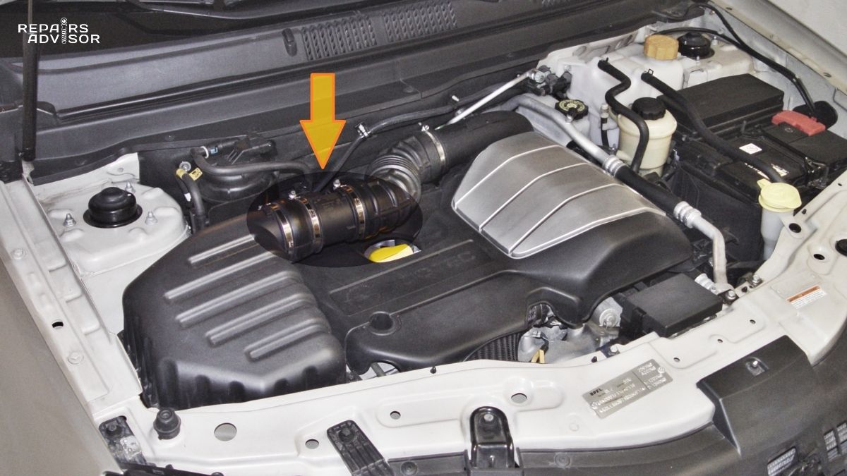
The mass air flow sensor—also known as a MAF sensor, air flow meter, or air mass sensor—is a precision electronic component strategically positioned between your air filter housing and throttle body. Unlike simpler volumetric flow sensors that merely measure air volume, the MAF sensor determines the actual mass of air flowing into your engine’s intake system.
This distinction matters significantly because air density changes constantly based on temperature, altitude, and whether your vehicle uses forced induction like a turbocharger. A cubic foot of cold air at sea level contains substantially more oxygen molecules than the same volume of hot air at high elevation. Your engine needs to know the actual mass of air—not just the volume—to calculate the correct amount of fuel for optimal combustion.
The sensor continuously monitors airflow and sends this data as an electrical signal to your vehicle’s Engine Control Unit (ECU). The ECU uses this information along with inputs from other sensors to determine exactly how much fuel to inject into each cylinder, ensuring your engine maintains the ideal 14.7:1 air-fuel ratio that maximizes power, efficiency, and minimizes emissions.
Modern fuel injection systems depend entirely on accurate MAF sensor readings. Without this crucial data, your ECU essentially operates blindly, unable to precisely meter fuel delivery. This is why even minor MAF sensor contamination can cause noticeable performance issues—the sensor’s measurements directly determine how your engine runs at every moment of operation.
Role in Engine Management
The MAF sensor serves as a cornerstone component within your vehicle’s comprehensive engine management system. While fuel delivery represents its primary function, the ripple effects of MAF sensor data extend throughout your vehicle’s operation in ways that might surprise you.
Fuel Injection Control: Every time you press the accelerator, the MAF sensor detects the increased airflow and instantly relays this information to the ECU. Within milliseconds, the ECU calculates the corresponding fuel requirement and adjusts injector pulse width accordingly. This real-time adjustment happens thousands of times per minute, continuously fine-tuning the air-fuel mixture as driving conditions change.
Ignition Timing Optimization: Beyond fuel delivery, the MAF sensor data helps the ECU determine optimal spark timing. Higher airflow rates indicate increased engine load, requiring adjusted ignition timing to prevent knock and maximize power output. The ignition system relies on this information to determine precisely when to fire each spark plug.
Transmission Control: In vehicles with automatic transmissions, the ECU uses MAF sensor readings to calculate engine load and determine appropriate shift points. When the sensor detects high airflow during acceleration, the transmission holds gears longer to maximize power delivery. Conversely, light airflow during cruising triggers earlier upshifts for improved fuel economy. A faulty MAF sensor can cause erratic shifting or transmission behavior that seems unrelated to an air intake component.
Emissions System Management: The MAF sensor works in tandem with oxygen sensors to maintain emissions within legal limits. The ECU compares expected exhaust composition (based on MAF readings and fuel delivery) against actual oxygen sensor data. Significant discrepancies trigger diagnostic codes and illuminate your check engine light, alerting you to potential issues before they cause catalytic converter damage.
Auxiliary System Control: Even systems that seem disconnected from air intake can be affected by MAF sensor data. Some vehicles adjust power steering assist levels based on engine load calculated from airflow. Others modify air conditioning compressor engagement to prevent power loss during acceleration. The fuel pump may increase pressure anticipating higher fuel demand based on increased airflow detection.
This interconnected relationship explains why MAF sensor problems can manifest in seemingly unrelated systems. What appears as a transmission issue or a general performance problem often traces back to inaccurate airflow measurement affecting the entire engine management strategy.
How Mass Air Flow Sensors Work
Operating Principles
Mass air flow sensors operate on thermal anemometer principles—a technology that sounds complex but relies on a beautifully simple concept: moving air cools heated objects. The sensor’s fundamental job is to measure how much electrical current is required to maintain a heated element at a constant temperature as air flows past it. The faster the air flows, the more current needed, and this current measurement directly correlates to air mass flow rate.
The sensor housing contains a small heated element positioned directly in the air stream. This element is precisely heated to a specific temperature above the incoming air temperature—typically 100-200°F warmer than ambient. As air flows through the intake system and past this element, it carries away heat through convection. The sensor’s internal electronics continuously measure the temperature difference and adjust electrical current to the heating element to maintain the target temperature.
Here’s where the physics becomes crucial: the amount of heat transferred from the element to the passing air depends not just on air velocity, but also on air density. Cold, dense air removes more heat than warm, thin air moving at the same speed. This is precisely why MAF sensors measure mass flow rather than volumetric flow—they inherently account for air density variations caused by temperature changes, altitude differences, and forced induction boost pressure.
The sensor samples only a small portion of the total air stream flowing through the intake tube. The housing design creates laminar (smooth, non-turbulent) airflow conditions across the sensing element, ensuring accurate and repeatable measurements. Most sensors include a fine mesh screen upstream of the sensing element to straighten and stabilize the airflow, reducing measurement errors caused by turbulence.
Modern MAF sensors also incorporate an intake air temperature sensor—either as a separate element within the same housing or integrated into the measurement system. This temperature data helps the ECU further refine fuel calculations and provides backup information if the primary MAF measurement becomes questionable.
Hot Wire vs. Hot Film Technology
While all modern MAF sensors use thermal measurement principles, they employ two distinct technologies that differ in construction, durability, and performance characteristics.
Hot Wire MAF Sensors
Hot wire sensors represent the original thermal MAF technology, first appearing in production vehicles during the mid-1980s. These sensors use an extremely thin platinum or nickel wire—typically just 70 micrometers in diameter, about the thickness of a human hair—suspended across the air stream.
The wire is incorporated into a Wheatstone bridge circuit that maintains constant wire temperature regardless of airflow. As air flows past and cools the wire, the circuit automatically increases current to restore the target temperature. This current increase is measured and converted to a voltage signal that the ECU interprets as air mass flow rate.
Hot wire sensors excel in response time due to their extremely low thermal mass. The thin wire heats and cools almost instantaneously, allowing the sensor to detect rapid changes in airflow with minimal lag. This quick response benefits engine performance during transient conditions like sudden acceleration or deceleration.
However, the delicate wire construction presents durability challenges. Dirt particles, oil droplets, or carbon deposits can coat the wire surface, insulating it and causing measurement errors. The wire must be robust enough to withstand constant vibration and thermal cycling yet thin enough for fast thermal response—a difficult engineering balance.
Many hot wire sensors address contamination through a clever burn-off feature. After engine shutdown, a relay applies high current to the wire for about one second, heating it to approximately 1000°C. This intense heat vaporizes oil films, carbon deposits, and other contaminants, maintaining sensor accuracy between cleanings. You might occasionally notice a faint smell or small wisp of smoke from your air intake immediately after shutting off your engine—this is the burn-off cycle in action.
Hot wire sensors typically output an analog voltage signal, usually ranging from 0.5 volts at idle to 4.5-5.0 volts at wide-open throttle. The ECU contains calibration tables that translate these voltage values into actual air mass flow rates specific to your engine configuration.
Hot Film MAF Sensors
Hot film technology evolved in the late 1980s and early 1990s as manufacturers sought more robust alternatives to fragile hot wire designs. Instead of a suspended wire, hot film sensors use a flat, thick-film resistor element—essentially a metallic grid or film deposited onto a ceramic substrate.
The film element operates on identical thermal principles as hot wire sensors but offers significant construction advantages. The flat geometry makes the sensing surface less susceptible to oil and debris accumulation—particles that would coat a round wire tend to deflect off the flat surface. The thicker construction also improves mechanical durability, better withstanding the harsh under-hood environment of vibration, temperature extremes, and occasional backfire events.
Most hot film sensors output a frequency signal rather than analog voltage. The frequency varies from approximately 30 Hz at idle to 150 Hz at wide-open throttle, though some modern variants use voltage output similar to hot wire sensors. Frequency-based signals offer advantages in electrical noise immunity—digital pulses are less susceptible to interference from ignition systems and other electrical components than analog voltage signals.
The trade-off for improved durability is slightly slower response time compared to hot wire sensors. The increased thermal mass of the film element takes microseconds longer to heat and cool, though this difference is imperceptible in normal driving and only matters in racing applications requiring absolute minimum sensor lag.
Some hot film designs incorporate dual temperature sensing elements—one on each side of a central heating element. This configuration allows the sensor to detect airflow direction, identifying reverse flow during intake valve overlap or backfire conditions. This additional data helps the ECU make more accurate fuel calculations during transient conditions.
Modern hot film sensors have largely replaced hot wire designs in new vehicle production due to their superior contamination resistance and longer service life. However, millions of vehicles with hot wire sensors remain on the road, and replacement sensors must match the original technology—the two types are not interchangeable even if connectors physically fit.
Understanding which type your vehicle uses helps determine maintenance intervals and cleaning frequency. Hot wire sensors generally require more frequent attention, while hot film sensors can often operate longer between cleanings under similar conditions.
Signal Processing and ECU Communication
The raw electrical signal from the MAF sensor’s heating element circuit requires processing before the ECU can use it for fuel calculations. This processing happens in sophisticated electronics integrated within the sensor housing itself.
For analog voltage-type sensors, the processing circuit converts the heating current measurement into a standardized voltage output, typically ranging from 0 to 5 volts. This voltage-to-airflow relationship follows a carefully calibrated curve that accounts for the specific characteristics of the sensing element and air intake tube diameter. The curve is non-linear—voltage increases more rapidly at higher airflow rates than at idle, reflecting the physics of thermal transfer.
Frequency-based sensors include oscillator circuits that convert the thermal measurement into a digital pulse train. The ECU measures either the frequency (pulses per second) or period (time between pulses) of this signal to determine air mass flow. Digital signals offer inherent advantages in noise immunity since the ECU only needs to detect pulse transitions, not precise voltage levels that could be corrupted by electrical interference.
The processed signal travels through a dedicated wire in the sensor’s connector to the ECU. This signal wire is typically shielded or uses twisted-pair construction to minimize electromagnetic interference from the ignition system, alternator, and other electrical components. A poor ground connection or damaged signal wire can cause erratic sensor readings that mimic actual sensor failure.
Inside the ECU, the MAF signal undergoes further processing through calibration tables that translate the voltage or frequency into actual air mass flow rates expressed in grams per second. These tables are specific to each engine configuration, accounting for factors like intake tube diameter, air filter restriction, and altitude compensation.
The ECU combines MAF data with inputs from other sensors—throttle position, engine speed from the crankshaft position sensor, coolant temperature, and oxygen sensor feedback—to calculate optimal fuel injection pulse width. This calculation happens thousands of times per minute, continuously adjusting the air-fuel ratio as conditions change.
Some vehicles employ redundancy or cross-checking strategies using both MAF and MAP (Manifold Absolute Pressure) sensors. The ECU compares airflow calculations from both sensors and flags discrepancies as potential faults. This redundancy helps identify sensor failures before they significantly impact engine performance.
Common MAF Sensor Problems and Symptoms
Primary Failure Causes
Contamination stands as the overwhelmingly most common cause of MAF sensor malfunction, accounting for the vast majority of sensor-related problems. Unlike catastrophic electronic failures, contamination develops gradually, causing progressive performance degradation that drivers often adapt to without realizing their vehicle is underperforming.
The contamination process begins innocently enough. Every time your engine draws air through the intake system, it’s pulling in microscopic dust particles, pollen, oil vapor from the crankcase ventilation system, and combustion byproducts that backflow during valve overlap. Your air filter blocks the majority of these contaminants, but no filter achieves 100% efficiency.
Over thousands of miles, these particles accumulate on the MAF sensor’s delicate sensing elements. Even a microscopic film of oil or dust alters the thermal characteristics of the hot wire or film element, insulating it from the passing air stream. The sensor requires more current to maintain its target temperature, causing it to report artificially high airflow rates. The ECU responds by injecting more fuel than necessary, creating a rich-running condition that wastes gas and can eventually damage your catalytic converter.
The contamination timeline varies dramatically based on operating conditions. Vehicles in dusty environments or those driven primarily on dirt roads may experience significant MAF contamination within 18,000-25,000 miles. Urban drivers in relatively clean conditions might not notice issues until 80,000-125,000 miles. Interestingly, smaller engines in compact cars often suffer earlier contamination because the restricted engine bay concentrates contaminants near the air intake system.
Over-oiled performance air filters represent a particularly insidious contamination source. These high-flow filters use oil to trap particles, and enthusiastic owners sometimes apply excessive oil during cleaning. The oil migrates through the filter media and accumulates on the MAF sensor, causing rapid performance degradation. If you use an oiled filter, apply oil sparingly and allow it to soak in completely before installation.
Physical damage causes less frequent but more dramatic MAF failures. The thin sensing wire in hot wire sensors can break from excessive vibration, impact from debris that bypasses the air filter, or thermal stress from repeated heating and cooling cycles. Hot film sensors are more robust but can still suffer housing cracks that allow unmetered air to bypass the sensing element, corrupting measurements.
Water damage presents special challenges. Driving through deep puddles can suck water into the air intake, potentially flooding the MAF sensor. While most sensors survive water exposure after drying, the moisture can leave mineral deposits on the sensing elements or cause corrosion in electrical connections. Some vehicles install the MAF sensor low in the air intake path where it’s particularly vulnerable to water ingestion.
Electronic failures affect the internal circuitry that processes the thermal measurements and generates the output signal. Transistors can short-circuit, resistors can drift out of specification, and solder joints can crack from thermal cycling and vibration. These failures typically occur suddenly rather than progressively, causing immediate and obvious performance problems.
The electrical connector represents another failure point. Corrosion, moisture intrusion, or simple wear can create intermittent connections that cause erratic sensor readings. Terminal corrosion is particularly common in humid climates or coastal areas where salt air accelerates the oxidation process.
Recognizable Symptoms
MAF sensor problems manifest through a constellation of symptoms that often overlap with other engine management issues. This symptom overlap makes proper diagnosis essential before replacing parts—what appears to be a bad MAF sensor might actually be a vacuum leak, faulty fuel injector, or failing oxygen sensor.
Rough idling and stalling frequently announce MAF sensor contamination or failure. At idle, your engine requires precise air-fuel mixture control because any imbalance becomes immediately apparent. A contaminated MAF sensor reporting incorrect airflow causes the ECU to deliver improper fuel quantities, resulting in unstable engine speed. The tachometer needle may fluctuate between 500-1200 RPM instead of holding steady at the normal idle speed. In severe cases, the engine may stall completely when you come to a stop or try to idle in gear.
The sensation differs from normal engine roughness—MAF-related idle problems often feel like the engine is hunting for the correct speed, surging slightly then dropping back repeatedly. You might also notice excessive vibration felt through the steering wheel or seat, particularly when the air conditioning is running and further loading the engine.
Poor acceleration and sluggish throttle response signal that your engine isn’t receiving the fuel it needs to match the air entering the cylinders. When you press the accelerator, there’s a noticeable 2-3 second delay before the engine responds, almost as if you’re driving through molasses. This hesitation is particularly pronounced when merging onto highways or climbing hills where you need immediate power.
The problem stems from the MAF sensor under-reporting airflow to the ECU. When you open the throttle, more air rushes into the engine, but if the MAF sensor doesn’t accurately measure this increase, the ECU continues delivering idle-level fuel quantities. The resulting lean mixture can’t produce adequate power until the oxygen sensors detect the lean condition and force the ECU into closed-loop correction—but this takes several seconds, creating the frustrating delay.
Engine misfires occur when the air-fuel mixture becomes so imbalanced that combustion fails completely in one or more cylinders. You’ll feel this as a rough, stumbling sensation, often accompanied by a noticeable loss of power. The check engine light may flash rather than remaining steady—a flashing light indicates active misfires that can damage your catalytic converter and requires immediate attention.
MAF-related misfires typically worsen under load or during acceleration when the engine demands maximum performance. At idle or steady cruising, the mixture might be close enough to correct for the engine to run reasonably smoothly, but the added stress of acceleration exposes the sensor’s inability to accurately measure the increased airflow.
Fuel economy deterioration provides one of the clearest indicators of MAF sensor problems. Many drivers report sudden 15-30% decreases in miles per gallon—enough to notice you’re visiting the gas station much more frequently than normal. This dramatic change happens because a contaminated MAF sensor typically over-reports airflow, causing the ECU to inject excess fuel. Your engine literally runs rich, wasting gasoline that doesn’t contribute to power production.
Sometimes the excessive fuel causes black smoke from the exhaust—particularly noticeable during acceleration or at startup. The unburned fuel also creates a distinctive rotten egg smell from the catalytic converter as it works overtime to burn the excess hydrocarbons. This overworking can permanently damage the converter, turning a $200 sensor problem into a $1,500 converter replacement.
Conversely, a MAF sensor that under-reports airflow creates a lean-running condition. While this might temporarily improve fuel economy numbers, it robs your engine of power and can cause damage from excessive combustion temperatures. Lean conditions are actually more dangerous than rich conditions because they can lead to detonation (engine knock) and pre-ignition.
Check engine light illumination almost always accompanies significant MAF sensor problems. The most common diagnostic trouble codes include:
- P0100: Mass Air Flow Circuit Malfunction (general sensor circuit problem)
- P0101: Mass Air Flow Circuit Range/Performance (sensor reading outside expected range)
- P0102: Mass Air Flow Circuit Low Input (sensor reporting impossibly low airflow)
- P0103: Mass Air Flow Circuit High Input (sensor reporting impossibly high airflow)
- P0104: Mass Air Flow Circuit Intermittent (sensor signal cutting in and out)
Additionally, MAF problems frequently trigger lean condition codes:
- P0171: System Too Lean (Bank 1)
- P0174: System Too Lean (Bank 2)
These lean codes occur when the oxygen sensors detect insufficient fuel delivery, often because a faulty MAF sensor is under-reporting airflow and the ECU isn’t commanding enough fuel injection. While multiple issues can cause lean codes, MAF sensor contamination ranks among the most common culprits.
If you experience any combination of these symptoms—particularly rough running paired with decreased fuel economy and a check engine light—the MAF sensor deserves investigation. You can learn more about checking your check engine light and understanding what those diagnostic codes mean through your vehicle’s onboard diagnostics.
Remember that symptoms alone don’t confirm MAF sensor failure. Similar issues can arise from dirty air filters, vacuum leaks, faulty spark plugs, or problems with other sensors in the engine management system. Proper diagnostic procedures distinguish between these possibilities, preventing unnecessary part replacement.
Diagnosing MAF Sensor Issues
Professional Diagnostic Procedures
Professional mechanics employ systematic diagnostic approaches that go far beyond simply plugging in a code reader and replacing whatever component the code mentions. This methodical process saves time and prevents the costly mistake of replacing functional parts.
Scan tool testing represents the gold standard for MAF sensor diagnosis because it allows real-time observation of sensor behavior under various operating conditions. A professional-grade scan tool connects to your vehicle’s diagnostic port and displays live data from all engine sensors simultaneously.
The diagnostic process begins with the engine at normal operating temperature. The technician monitors MAF sensor readings while noting engine RPM, throttle position, and calculated engine load. For a typical 2.4-liter four-cylinder engine, expected MAF readings might look like this:
- Idle (900 RPM): 2-4 grams per second
- 1,000 RPM (light throttle): 5-8 g/s
- 2,000 RPM (moderate acceleration): 12-18 g/s
- 3,000 RPM (hard acceleration): 25-35 g/s
These numbers vary significantly based on engine displacement—a 5.0-liter V8 might show 8-10 g/s at idle versus 2-4 g/s for a small four-cylinder. What matters more than absolute values is the relationship between RPM, throttle position, and airflow readings. The technician compares your vehicle’s actual readings against either factory specifications or data from a known-good vehicle with the same engine.
Several red flags indicate MAF sensor problems during scan tool testing:
- Readings that don’t change smoothly as RPM increases suggest internal sensor problems
- Values that seem too high or low for the operating conditions indicate calibration drift
- Erratic fluctuations at steady throttle point to electrical connection issues or internal sensor damage
- Readings that don’t respond to rapid throttle changes suggest a dead or dying sensor
The scan tool also reveals how the ECU is compensating for questionable MAF data. Fuel trim values show real-time adjustments the ECU makes to maintain proper air-fuel ratios. Excessively positive fuel trims (above +10%) indicate the ECU is adding extra fuel to compensate for a lean condition—possibly from a MAF sensor under-reporting airflow. Negative fuel trims (below -10%) suggest the opposite: the ECU removing fuel to correct for a rich condition caused by a MAF sensor over-reporting airflow.
Visual and physical inspection often reveals problems that scan tools can’t detect. The technician removes the MAF sensor from the intake tube and examines the sensing elements with a bright light. Even slight discoloration, film buildup, or oil residue indicates contamination that affects accuracy. Broken wires or cracked housings are immediately obvious and confirm the need for replacement rather than cleaning.
The electrical connector receives close scrutiny for signs of corrosion, pushed-back pins, or moisture intrusion. A quick test of connector pins with a multimeter verifies proper power supply (typically 12 volts), ground connection, and signal wire continuity. Many intermittent MAF problems trace to corroded or loose electrical connections rather than actual sensor failure.
The air intake system inspection extends beyond the sensor itself. Mechanics check for cracks in the intake tube between the MAF sensor and throttle body—any air leak downstream of the sensor allows unmetered air to enter the engine, corrupting the air-fuel mixture. They also verify the air filter is properly seated with no gaps allowing unfiltered air to bypass the filter and contaminate the sensor.
Voltage and frequency testing with a multimeter provides additional diagnostic data. With the ignition on but engine off, the reference voltage to the MAF sensor should measure 4.5-5.0 volts. At idle, a hot wire sensor might output 0.8-1.2 volts, increasing to 4.0-4.5 volts at wide-open throttle. Hot film sensors showing 30-40 Hz at idle should increase to 120-150 Hz under acceleration.
Deviations from these expected values—particularly a signal wire stuck at one voltage or frequency regardless of engine speed—confirm sensor failure. However, interpreting these measurements requires experience and knowledge of the specific vehicle’s specifications, which is why professional diagnosis offers value beyond simple code reading.
DIY Testing Methods
While comprehensive diagnosis requires professional tools, several DIY tests can help you determine whether your MAF sensor is likely causing your performance issues.
The unplug test offers a quick, free diagnostic that works on most vehicles. Here’s the procedure:
- Start your engine and note how it idles and responds to throttle
- Turn off the engine and disconnect the MAF sensor’s electrical connector
- Restart the engine with the MAF disconnected
- Observe whether the engine runs better, worse, or about the same
If the engine runs noticeably better with the MAF disconnected, you’ve likely found your problem. With no MAF signal, the ECU switches to a backup strategy using the throttle position sensor and engine speed to estimate airflow. This “limp mode” won’t provide optimal performance, but if it’s better than running with the faulty sensor connected, the MAF is definitely the culprit.
Important caveat: The check engine light will illuminate immediately when you disconnect the MAF sensor, and you’ll likely see reduced power since the ECU can’t precisely meter fuel without airflow data. This test is purely diagnostic—you shouldn’t drive the vehicle extensively with the sensor disconnected.
Visual inspection requires no special tools and can reveal obvious problems. Remove the sensor from the intake tube (usually held by two screws or clamps) and shine a flashlight into the sensor bore. You’re looking for:
- Dirt or debris on the sensing elements
- Oil film coating the wires or film element
- Broken wires in hot wire sensors (visible as a gap in the wire)
- Damaged housing with cracks that allow air leaks
Even if contamination isn’t visible to the naked eye, you might detect an oily feel when gently touching the housing interior with a clean cotton swab. Any oil residue indicates contamination that affects sensor accuracy.
The tap test helps identify intermittent electrical failures within the sensor. With the engine idling, gently tap the sensor housing with a screwdriver handle or similar tool. If the engine RPM changes, stumbles, or stalls in response to tapping, internal electrical connections are breaking down. This test was particularly useful for older hot film sensors prone to internal solder joint failures, though modern sensors have improved reliability.
Important safety notes for DIY diagnosis:
- Always disconnect the battery before removing or installing electrical components to prevent short circuits
- Never touch the MAF sensing elements with your fingers—skin oils cause contamination
- Don’t use compressed air to clean the sensor—the pressure can damage delicate components
- If you’re uncomfortable working with electrical systems, professional diagnosis is worth the cost
These DIY tests can confirm suspicions and help you make informed decisions about whether to attempt cleaning or proceed directly to replacement. However, they don’t replace comprehensive diagnosis, especially if you’re experiencing intermittent problems or multiple engine symptoms that might not be MAF-related.
Understanding when your symptoms match common MAF failure patterns versus when they suggest other issues requires experience. If DIY testing doesn’t clearly identify the problem, or if you’re uncertain about your results, professional diagnosis prevents the costly mistake of replacing a functioning sensor while the actual problem continues causing damage.
Cleaning Your MAF Sensor
When Cleaning is Appropriate
Cleaning can restore a contaminated MAF sensor to proper function—but only if contamination is the sole problem. Understanding when cleaning will help versus when you’re wasting time and cleaner on a sensor that needs replacement saves frustration and money.
Ideal cleaning candidates share several characteristics:
- Gradual performance degradation over time rather than sudden failure
- Check engine codes specifically indicating range or performance issues (P0101) rather than circuit faults
- Visible dirt or oil film when you inspect the sensor
- Vehicle has high mileage since last air filter replacement
- Recent installation of an oiled performance air filter
Cleaning proves most effective when caught early. A sensor with light contamination responds dramatically to proper cleaning, while heavily fouled sensors might only show partial improvement. If you’ve been ignoring symptoms for months or years, the contamination may be too severe for cleaning to restore full function.
Cleaning won’t help if:
- The sensing wire is visibly broken (hot wire sensors)
- The housing shows cracks or physical damage
- Electrical connections are corroded beyond cleaning
- The sensor shows no response during testing (completely dead)
- Diagnostic testing reveals internal electronic failures
One effective decision-making approach: if your vehicle fails the unplug test—meaning it runs the same or worse with the MAF disconnected—cleaning is worth attempting before replacement. However, if the sensor shows no electrical output at all during testing, replacement is inevitable.
Preventive cleaning during routine maintenance prevents many problems before they affect performance. Consider cleaning your MAF sensor every time you replace your air filter, typically every 15,000-30,000 miles. This proactive approach costs only a few dollars in cleaner and fifteen minutes of time while preventing expensive performance issues down the road.
The contamination source matters too. Oil from over-application to performance filters responds well to cleaning. Road dust and normal dirt usually clean effectively. However, carbon deposits from excessive crankcase blowby or chemical contamination from fuel additives or octane boosters may prove more stubborn, requiring multiple cleaning attempts or eventual replacement.
Required Materials
Using the correct cleaning products and tools makes the difference between successful sensor restoration and permanent damage. The wrong cleaner can destroy a MAF sensor in seconds, so this is one area where cutting corners proves extremely expensive.
Essential cleaner: Purchase dedicated MAF sensor cleaner spray—brands like CRC MAF Sensor Cleaner, Gumout MAF Sensor Cleaner, or OEM-specified products. These specialized formulas use solvents that evaporate completely without leaving residue and are specifically formulated not to damage the sensor’s delicate components.
Never use these products regardless of how clean they might get other components:
- Brake cleaner (too aggressive, damages plastics and electronics)
- Carburetor cleaner (leaves residue, attacks sensor materials)
- Electrical contact cleaner (may leave conductive residue)
- WD-40 or other penetrating oils (leaves film that ruins sensors)
- Alcohol or solvents not specifically designed for MAF sensors
The cost difference between proper MAF cleaner ($8-12 per can) and a replacement sensor ($150-380) makes using the correct product an obvious choice. One wrong spray of brake cleaner can destroy a sensor that would have been completely restored with proper MAF cleaner.
Additional materials:
- Clean, lint-free microfiber cloths (for wiping housing exterior only)
- Appropriate screwdrivers or tools to remove sensor from intake tube
- Safety glasses (protect your eyes from spray)
- Work gloves (optional, but prevent fingerprints on housing)
- Flashlight (for inspecting sensor internals)
Tools for sensor removal: Most sensors attach with two small screws (Phillips or Torx head) or spring clamps. Check your specific vehicle to determine what you’ll need. Some European vehicles use tamper-proof fasteners requiring special bits, though standard tools usually work with careful application.
Step-by-Step Cleaning Procedure
Follow this systematic process for safe, effective MAF sensor cleaning that restores performance without risking damage.
Preparation Phase:
- Park on level ground with the engine completely cool
- Disconnect the negative battery terminal (prevents electrical issues during work)
- Locate your MAF sensor on the intake tube between the air filter box and throttle body
- Take a photo of the sensor installation for reference during reassembly
Sensor Removal:
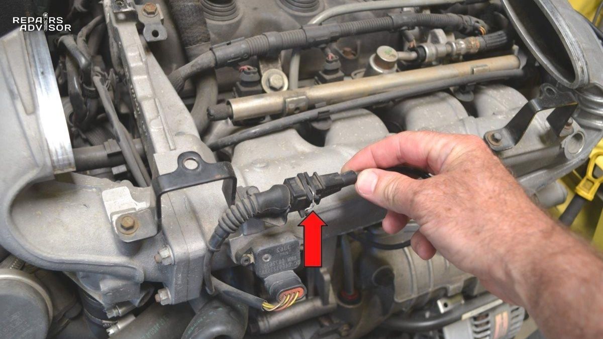
- Disconnect the electrical connector by pressing the release tab and pulling straight back—never twist or force the connector
- Note the connector orientation for reinstallation
- Remove the fasteners (screws or clamps) securing the sensor to the intake tube
- Gently slide the sensor from its housing, being careful not to bump the sensing elements
- Inspect the rubber sealing gasket for cracks, tears, or hardening—replace if damaged
Cleaning Process:
- Take the sensor to a well-ventilated outdoor area or open garage
- Place it on a clean towel with the sensing elements facing up
- Shake the MAF cleaner can thoroughly
- Hold the can 4-5 inches (100-120mm) away from the sensor opening
- Apply 10-15 short bursts of cleaner, not one continuous spray
- Focus on the sensing elements visible inside the bore
- Also spray the intake air temperature sensor (if integrated in the same housing)
- Lightly spray the housing interior and electrical terminals
- Critical warning: Never spray directly onto hot wire elements from close range—the force can break the delicate wire
What NOT to do during cleaning:
- Don’t touch the sensing elements with fingers, swabs, or brushes
- Don’t use compressed air—pressure can break wires
- Don’t wipe the sensing elements with cloth or paper towels
- Don’t force-dry with heat guns or hair dryers
- Don’t spray from closer than 4 inches away
Drying Period:
- Set the sensor aside in a clean, dust-free location
- Allow 5-10 minutes for complete solvent evaporation
- MAF cleaner evaporates quickly (similar to alcohol), but patience ensures no liquid remains
- While waiting, clean the sensor mounting area in the intake tube
- Check your air filter condition—if it’s dirty, replace it now
Inspection During Cleaning: While the sensor dries, examine it closely:
- Look for broken wires or damaged film elements
- Check for housing cracks (indicates replacement needed)
- Inspect the screen for damage (if equipped)
- Verify electrical pins aren’t bent or corroded
Reinstallation:
- Verify the sensor is completely dry (wait longer if any doubt)
- Inspect the mounting gasket or O-ring—replace if worn
- Carefully slide the sensor back into the intake tube housing
- Ensure proper alignment (the sensor only fits one way)
- Install and tighten fasteners to a snug fit (don’t overtighten plastic threads)
- Reconnect the electrical connector—listen for the click indicating proper seating
- Reconnect the battery negative terminal
Post-Cleaning Verification:
- Start the engine and let it idle for 30 seconds
- Check for smooth, stable idle with no unusual sounds
- Verify no air leaks at the sensor mounting point
- Test drive the vehicle for 10-15 minutes
- Monitor for performance improvement
- If the check engine light was on, it may take several drive cycles to turn off, or you can use a code reader to clear it manually
Maintenance Frequency: Clean your MAF sensor every 15,000-30,000 miles or whenever you replace your air filter. This preventive approach maintains sensor accuracy and prevents performance-robbing contamination from accumulating. The 10-minute investment every couple of years saves potential hundreds in fuel waste and repair costs.
If cleaning doesn’t resolve your symptoms after allowing a few days for the ECU to relearn fuel trims, the sensor likely has internal damage or electronic failure requiring replacement. Don’t repeatedly clean a sensor that doesn’t respond—you’re just delaying inevitable replacement while potentially allowing continued engine damage from incorrect fuel delivery.
Replacing a MAF Sensor
When Replacement is Necessary
Sometimes cleaning can’t rescue a MAF sensor, and replacement becomes the only solution for restoring proper engine performance. Recognizing when you’ve reached this point prevents wasted time on attempted repairs that can’t succeed.
Replace rather than clean when you observe:
Physical damage: If the sensing wire is broken (you’ll see a visible gap in hot wire sensors), the sensor is beyond repair. Cracked housings that allow unmetered air to bypass the sensing element also require replacement—no amount of cleaning fixes structural damage.
Failed cleaning attempts: If you’ve properly cleaned the sensor using correct procedures and products, yet symptoms persist unchanged after several days of driving, the sensor has failed internally. The ECU needs this time to relearn fuel trim adjustments, so give cleaning a fair chance before condemning the sensor. However, if performance remains poor after a week, replacement is necessary.
Complete electrical failure: When diagnostic testing shows no output from the sensor regardless of engine speed or airflow—essentially a “dead” sensor—internal electronics have failed. These electronic components can’t be repaired and require sensor replacement.
Severe contamination resistance: Some contamination, particularly carbon buildup from excessive oil consumption or chemical deposits from fuel additives, may resist even proper cleaning. If the sensor still shows visible heavy contamination after cleaning, or if contamination returns within days, replacement proves more cost-effective than repeated cleaning attempts.
Intermittent failures that cleaning doesn’t resolve: If your sensor causes intermittent problems that come and go unpredictably, and cleaning doesn’t eliminate these episodes, internal solder joints or components are likely failing due to thermal cycling or vibration. These intermittent electrical failures won’t improve with cleaning.
Collision or water damage: If your vehicle has been in a front-end collision affecting the air intake area, or if you’ve driven through deep water that flooded the intake system, the MAF sensor may have sustained damage that isn’t immediately visible. Water can leave mineral deposits that cleaning can’t remove or cause internal corrosion that progressively worsens.
The decision point ultimately comes down to economics: a $10 can of MAF cleaner and 20 minutes of time represents minimal investment with significant potential return. However, once you’ve made a proper cleaning attempt without success, further delay just extends the period of poor performance, wasted fuel, and potential catalytic converter damage from incorrect air-fuel mixtures.
Selecting the Correct Replacement
Choosing the right replacement sensor involves more than just finding one that physically fits—you need a sensor that matches your vehicle’s specifications and provides reliable long-term performance.
OEM (Original Equipment Manufacturer) Parts come from the same supplier that built your vehicle’s original sensor, though they may carry the vehicle manufacturer’s brand. These sensors offer several advantages:
- Guaranteed compatibility: Exact specifications matching your engine’s calibration
- Pre-calibrated from factory: No adaptation or programming needed
- Best reliability: Proven design with quality control
- Warranty support: Vehicle manufacturer stands behind the part
The primary disadvantage is cost—OEM MAF sensors typically run $120-380 depending on vehicle make and model. Luxury and performance vehicles command the highest prices, while economy car sensors cost less.
Aftermarket Replacement Options come from independent parts manufacturers and offer lower prices, typically $65-150. However, quality varies dramatically between brands:
Reputable aftermarket brands worth considering:
- Bosch: Major OEM supplier, excellent quality and reliability
- Denso: Another OEM supplier making aftermarket versions
- Hitachi: Quality sensors for Japanese vehicles especially
- Standard Motor Products: Broad coverage, reasonable quality
- Walker Products: Specialized in emissions components
These quality aftermarket brands often provide OEM-equivalent performance at 20-40% cost savings. They may require a brief adaptation period where the ECU learns the new sensor’s characteristics, but performance generally matches OEM parts.
Avoid ultra-cheap no-name brands: The $30 MAF sensor sold on generic online marketplaces often uses inferior materials, poor calibration, and inadequate quality control. These sensors may work initially but fail quickly, sometimes within months. The false economy of cheap sensors becomes apparent when you’re replacing them repeatedly or dealing with persistent performance issues.
Critical Compatibility Verification: Before purchasing any sensor, verify:
- Exact vehicle year, make, model, and engine (a 2015 Honda Accord 2.4L uses a different sensor than the 3.5L V6 version)
- Part number cross-reference (compare the numbers on your original sensor to the replacement)
- Connector configuration (physical connector must match exactly)
- Sensor technology type (hot wire vs. hot film—these aren’t interchangeable)
Some vehicles within the same model line use different MAF sensors for different markets or production dates. The only certain way to verify compatibility is matching part numbers or using a reliable parts catalog specific to your vehicle’s VIN (Vehicle Identification Number).
Important compatibility warning: Certain vehicles, particularly some European makes like BMW, Volkswagen, and Audi, use different MAF sensor types even within the same model year depending on engine variant or market. A sensor that physically fits your intake tube might use completely different electrical characteristics that won’t work with your ECU. This is why part number verification proves essential—the connector fitting doesn’t guarantee compatibility.
When possible, bring your old sensor to the parts store for side-by-side comparison with the replacement. Verify the connector matches exactly, the mounting holes align, and the physical dimensions are identical. These simple checks prevent purchasing an incompatible part that waste
s your time and money.
DIY Replacement Procedure
Replacing a MAF sensor ranks among the easier automotive repairs, well within the capabilities of most DIY enthusiasts with basic tools and mechanical aptitude. The job typically takes 15-30 minutes for straightforward installations.
Required Tools:
- Appropriate screwdrivers (Phillips or flathead, depending on your vehicle)
- Clean cloth or towels
- New air filter (recommended to install simultaneously)
- MAF sensor cleaner (to clean the housing)
- Optional: torque wrench if specifications provided
Before You Begin:
- Purchase the correct replacement sensor (verify part numbers)
- Consider replacing your air filter at the same time—dirty filters contribute to sensor contamination
- Gather your tools in a clean work area
- Disconnect the battery negative terminal for safety
Step-by-Step Installation:
Step 1 – Access and Removal:
- Locate your MAF sensor on the intake tube between air filter and throttle body
- Disconnect the electrical connector by pressing the release tab
- Note the sensor’s orientation—some have a specific directional installation
- Remove the fastening screws or release clips holding the sensor
- Carefully slide the old sensor from the housing
- Set aside in a safe location (don’t discard until you verify the new one works)
Step 2 – Housing Preparation:
- Inspect the intake tube mounting surface for debris or damage
- Clean the tube interior with MAF sensor cleaner spray
- Wipe away any oil or dirt buildup
- Check the mounting gasket or O-ring—replace if worn, cracked, or hardened
- Verify no cracks in the intake tube itself
Step 3 – New Sensor Installation:
- Remove the new sensor from its packaging carefully
- Critical: Do not touch the sensing elements with your fingers
- Inspect for shipping damage (rare but possible)
- Verify the mounting gasket is properly positioned
- Align the sensor with the housing—it typically only fits one way
- Slide the sensor into place gently but firmly
- Install fasteners and tighten snugly (avoid overtightening plastic threads)
- If torque specifications are provided, follow them precisely
Step 4 – Electrical Connection:
- Inspect the electrical connector for corrosion or damage
- Align the connector with the sensor pins
- Push firmly until you hear/feel the locking tab click
- Verify the connection is secure by gently tugging on the connector
Step 5 – System Verification:
- If you removed the air filter box for access, reinstall it properly
- Ensure all intake components are secure with no air leaks
- Double-check that no tools or materials are left in the engine bay
- Reconnect the battery negative terminal
Step 6 – Initial Testing:
- Start the engine (it may run slightly rough for the first few seconds as the ECU recognizes the new sensor)
- Let it idle for 1-2 minutes while monitoring for smooth operation
- Listen for any unusual sounds indicating air leaks
- Verify the check engine light isn’t immediately illuminating
Step 7 – Test Drive and Adaptation:
- Drive the vehicle through varied conditions: idle, gentle acceleration, highway speed
- Note whether symptoms have resolved
- Some vehicles require 10-50 miles for the ECU to fully adapt to the new sensor
- During this period, you might experience minor hesitation or slightly rough running—this is normal
Step 8 – Code Clearing (if necessary):
- If the check engine light was on before replacement, use a code reader to clear codes
- Some vehicles will clear codes automatically after several successful drive cycles
- If the light returns after clearing, verify proper installation and check for other issues
Professional Installation Costs: If you prefer professional installation or encounter complications:
- Labor time: 0.3-0.5 hours (15-30 minutes)
- Labor cost: $50-100 depending on shop rates and location
- Total with parts: $250-525 typically
- Dealership vs. independent shops: Dealerships charge $100-150 more on average
Dealerships may offer advantages like verified OEM parts and manufacturer-trained technicians, while independent shops often provide better value with equal competence for straightforward repairs like MAF sensor replacement.
When to Seek Professional Help: Consider professional installation if:
- Your vehicle has a complex or difficult-to-access air intake system
- You’re uncomfortable working with electrical components
- The installation requires programming or adaptation with diagnostic equipment
- You lack confidence in your ability to properly verify the repair
- The vehicle is under warranty (DIY work could void coverage)
Post-Installation Monitoring: Over the next few days and weeks, verify:
- Symptoms have resolved completely
- Fuel economy returns to normal levels
- Engine performance feels smooth across all operating conditions
- No new check engine lights or warning codes appear
If problems persist after proper installation, other issues may be affecting your engine. The MAF sensor often gets blamed for symptoms caused by vacuum leaks, faulty injectors, or other engine management problems. Professional diagnosis can identify these additional issues.
Preventing MAF Sensor Problems
Maintenance Best Practices
Prevention costs far less than repair—a truth particularly applicable to MAF sensors where simple maintenance practices can extend sensor life from 50,000 miles to 150,000+ miles.
Air Filter Service represents the single most important preventive measure. Your air filter serves as the primary defense protecting the MAF sensor from contaminants. A quality filter maintained on schedule prevents 80-90% of potential sensor problems.
Replace your air filter according to manufacturer recommendations, typically every 15,000-30,000 miles for normal driving. However, adjust this interval based on conditions:
- Dusty environments: Replace every 10,000-15,000 miles
- Urban driving: Standard 15,000-30,000 mile intervals usually adequate
- Highway driving: May extend to upper end of interval range
- Off-road use: Inspect frequently, replace when visibly dirty regardless of mileage
Critical filter considerations:
- Use OEM-specification filters or quality equivalents—cheap filters often fit poorly or provide inadequate filtration
- Verify filters are designed for your specific vehicle’s intake system
- Check that replacement filters maintain proper airflow direction (arrows on filter indicate flow direction)
- Avoid over-oiled performance filters unless absolutely necessary for your application
When replacing your air filter, take these additional steps:
- Clean the air filter box with a damp cloth, removing accumulated debris
- Inspect the box sealing surfaces for cracks or warping
- Verify the air filter lid seals properly with no gaps
- Check for unusual debris in the box (leaves, insects, plastic bags)—these indicate air intake location problems
Air Intake System Integrity requires regular inspection to prevent unfiltered air from reaching the MAF sensor:
Check intake hoses and connections every oil change (approximately every 5,000-7,500 miles):
- Inspect rubber intake boots for cracks, especially near clamps
- Verify all clamp connections are tight and properly positioned
- Look for collapsed or crushed hoses restricting airflow
- Check for oil accumulation indicating crankcase ventilation issues
Replace deteriorated components immediately—a $20 intake hose costs far less than a $200 MAF sensor and potential engine damage from vacuum leaks.
Crankcase Ventilation System maintenance prevents oil vapor from contaminating the MAF sensor:
The PCV (Positive Crankcase Ventilation) system routes crankcase vapors back through the intake, potentially carrying oil mist that coats the sensor. Proper PCV maintenance minimizes this:
- Replace PCV valve per manufacturer schedule (typically 30,000-50,000 miles)
- Inspect crankcase breather hoses for oil accumulation
- Address excessive oil consumption promptly—burning oil indicates engine problems that also contaminate sensors
- Consider installing an oil catch can if your vehicle is prone to excessive crankcase vapor
Driving Habits and Operational Practices:
Several operational practices extend MAF sensor life:
- Allow warm-up in extreme cold: Letting your engine reach operating temperature before highway driving reduces condensation in the intake system
- Avoid deep water crossings: Water ingestion can flood and damage the sensor
- Use quality fuel: Lower-grade fuels produce more combustion deposits that backflow into the intake
- Address engine problems promptly: Running rich or consuming oil accelerates sensor contamination
Preventive Cleaning Schedule: Even with perfect maintenance, sensors gradually accumulate microscopic contamination. Preventive cleaning every 30,000-50,000 miles maintains optimal performance. This 10-minute task costs under $10 and prevents the performance degradation that develops so gradually you don’t notice until it’s severe.
Environmental Considerations and Service Life
Your operating environment dramatically affects MAF sensor longevity, sometimes more than how you maintain the vehicle.
Challenging Operating Conditions:
Desert and dusty environments: The fine dust particles in arid climates inevitably work past air filters, accelerating sensor contamination. Vehicles in these conditions may need air filter replacement every 7,500-10,000 miles and sensor cleaning every 20,000-30,000 miles. Some desert drivers install pre-filters or upgraded filtration systems to extend sensor life.
Coastal and high-humidity areas: Salt air and moisture promote corrosion in electrical connections and can leave mineral deposits on sensing elements. Applying dielectric grease to electrical connectors during maintenance helps prevent corrosion. Sensors in these environments may need more frequent inspection of electrical connections even if sensing elements remain clean.
Urban stop-and-go traffic: Contrary to intuition, city driving often proves easier on MAF sensors than highway miles because lower total airflow means less cumulative contamination. However, the rich-running conditions during frequent cold starts can create more carbon deposits.
Extreme cold climates: Condensation forms in intake systems during cold starts, potentially leaving mineral deposits as it evaporates. Additionally, road salt and chemicals used for de-icing can contaminate sensors if kicked up by traffic. Some cold-climate vehicles position the air intake higher to reduce contamination from road debris.
Off-road and recreational use: Dirt roads, trails, and dusty conditions absolutely devastate air filters and sensors. Serious off-road vehicles should use upgraded filtration systems and inspect filters after every off-road session. Sensors may need cleaning every 10,000-15,000 miles in these conditions.
Expected Service Life by Environment:
- Ideal conditions (highway driving, temperate climate, perfect maintenance): 150,000+ miles
- Normal conditions (mixed driving, average climate, good maintenance): 100,000-125,000 miles
- Challenging conditions (urban, dusty, or coastal with good maintenance): 50,000-75,000 miles
- Severe conditions (dusty, off-road, or poor maintenance): Failure possible at 18,000-30,000 miles
Cost-Benefit Analysis: A $15-30 air filter replaced every 15,000 miles costs roughly $50-100 over 100,000 miles. The same neglect could require a $250-500 MAF sensor replacement at 30,000-50,000 miles, plus the hidden costs of reduced fuel economy (potentially $500-1000 over time) and potential catalytic converter damage ($1,500-2,500 to replace). The economics clearly favor preventive maintenance.
Understanding your specific operating conditions helps you tailor maintenance intervals appropriately. Don’t just follow generic recommendations—adjust based on your actual environment and driving patterns for optimal sensor longevity.
Conclusion
Your vehicle’s mass air flow sensor operates behind the scenes, continuously measuring air entering your engine to ensure optimal performance, fuel economy, and emissions control. While this critical component typically provides reliable service for 100,000+ miles with proper maintenance, understanding how it works and recognizing failure symptoms empowers you to address problems before they escalate into expensive repairs.
The key takeaways from this comprehensive guide:
Prevention beats cure: Regular air filter replacement and basic intake system maintenance prevent 80% of MAF sensor problems. The small investment in preventive care delivers enormous returns in avoided repairs and maintained performance.
Early recognition saves money: The sooner you identify MAF sensor symptoms—rough idling, poor acceleration, decreased fuel economy, or check engine lights with P01xx codes—the more likely cleaning can restore function without replacement costs.
Proper diagnosis prevents waste: Not every rough-running engine needs a new MAF sensor. Systematic diagnostic procedures distinguish sensor problems from vacuum leaks, failing injectors, or other issues that cause similar symptoms.
Use correct products and procedures: The $10 investment in proper MAF sensor cleaner protects your $200-500 sensor investment. Using incorrect cleaners can permanently damage sensors in seconds.
Know your limits: While MAF sensor cleaning and replacement represent straightforward DIY tasks for mechanically inclined owners, recognizing when professional diagnosis or installation provides better value demonstrates wisdom rather than weakness.
Skill-Appropriate Actions:
- Beginners: Focus on maintaining proper air filter replacement schedules and recognizing symptoms early
- Intermediate DIYers: Tackle sensor cleaning, basic diagnosis, and straightforward replacements
- Advanced enthusiasts: Perform comprehensive diagnostics and handle complex repairs
When your vehicle exhibits MAF sensor symptoms—especially rough running combined with poor fuel economy—don’t delay investigation. The longer a faulty sensor operates, the more fuel you waste and the greater the risk of damaging your catalytic converter through incorrect air-fuel mixtures. Early intervention costs far less than compounding problems.
When Professional Help Makes Sense: Seek professional assistance if you experience:
- Persistent symptoms after proper cleaning attempts
- Multiple diagnostic trouble codes suggesting complex problems
- Uncertainty about diagnostic results or repair procedures
- Safety-critical symptoms like unexpected stalling in traffic
- Warranty coverage concerns about DIY repairs
Professional mechanics bring diagnostic equipment, technical databases, and experience that can quickly identify problems that might take DIYers hours to troubleshoot. Sometimes paying for expert diagnosis saves money compared to trial-and-error part replacement.
Final Maintenance Recommendation: Incorporate MAF sensor inspection and cleaning into your regular maintenance schedule alongside air filter replacement—typically every 15,000-30,000 miles. This proactive approach maintains optimal engine performance, preserves fuel economy, and prevents the gradual performance degradation that develops so slowly you adapt without realizing your vehicle isn’t running at its best.
Your mass air flow sensor represents a small component with outsized impact on your driving experience. Treat it with the respect it deserves through proper maintenance, and it will reward you with years of trouble-free performance, optimal fuel economy, and the satisfaction of keeping your vehicle running as its engineers intended.