Modern vehicles rely on disc brake systems as their primary safety mechanism, converting kinetic energy into thermal energy through controlled friction to bring thousands of pounds of moving metal to a safe stop. Whether you’re navigating rush-hour traffic, descending mountain grades, or making an emergency stop to avoid a collision, your disc brake system performs this critical function dozens of times every drive. Understanding how this complex integration of hydraulic, mechanical, and electronic components works together helps you make informed maintenance decisions, recognize warning signs of problems, and know when professional service is essential versus when DIY repairs are appropriate.
This comprehensive guide explores every aspect of disc brake systems, from the moment you press the brake pedal to the physics of friction happening at each wheel. We’ll examine the complete system architecture including master cylinders, brake boosters, hydraulic lines, calipers, rotors, and pads. You’ll learn the critical differences between floating and fixed calipers, understand why rotor design matters, and discover how brake pad material selection affects everything from stopping distance to wheel cleanliness. We’ll also cover the hydraulic principles that multiply your 50-pound pedal input into over 1,000 pounds of clamping force at each wheel, and explain why brake fluid specification isn’t just a minor detail but a safety-critical choice.
Whether you’re an intermediate DIY mechanic looking to perform your own brake service, a professional technician seeking deeper system knowledge, or a beginner trying to understand what your mechanic is telling you, this guide provides the technical depth and practical insights you need. We’ll address common brake problems like squealing, pulsation, and brake fade, outline preventive maintenance schedules, and establish clear boundaries between DIY-appropriate tasks and those requiring professional expertise. Your vehicle’s disc brake system is engineered with remarkable precision and built-in safety redundancy—understanding how it all works empowers you to keep it functioning optimally for years to come.
For foundational brake system knowledge, see our guide on How Disc Brakes Work: Caliper and Rotor Mechanics and How Master Cylinder & Booster Work: Hydraulic Brake Fundamentals.
Safety Disclaimer: Disc brake systems are safety-critical components where failure can have catastrophic consequences. While this guide provides comprehensive technical information for educational purposes, brake system service requires specific technical knowledge, proper tools, and safety equipment. If you experience brake problems—unusual noises, pedal changes, pulling to one side, or warning lights—have your vehicle inspected by a qualified technician immediately. Never drive a vehicle with compromised braking performance. The information provided here is for understanding brake system operation and making informed decisions about when to seek professional service.
Disc Brake System Architecture and Components
A complete disc brake system represents one of the most sophisticated safety mechanisms in your vehicle, transforming mechanical pedal input into precisely controlled hydraulic pressure that generates massive clamping forces at each wheel. The system architecture follows a carefully engineered path from driver input to wheel deceleration, with built-in redundancy and fail-safes designed to maintain partial braking capability even if certain components fail. Modern disc brake systems integrate mechanical linkages, hydraulic circuits, friction components, and electronic control modules into a cohesive safety network that responds in milliseconds to driver commands.
The brake pedal assembly serves as the driver’s interface with the entire system, featuring a lever mechanism that provides the first stage of force multiplication. Most brake pedals employ a mechanical ratio of 4:1 to 6:1, meaning your 50-pound foot pressure becomes 200 to 300 pounds of force transmitted to the brake booster. This mechanical advantage is just the beginning of the force multiplication chain. The pedal assembly also houses the brake light switch that illuminates your stop lamps and signals modern engine management systems to cut fuel delivery during deceleration, improving fuel economy and emissions.
The brake booster, also called a power brake unit, provides the second critical stage of force multiplication. Traditional vacuum-assisted boosters use engine intake manifold vacuum to amplify the pedal force by an additional 3 to 5 times, allowing a total of 600 to 1,500 pounds of force to reach the master cylinder with only moderate pedal effort. Modern vehicles increasingly use electric brake boosters that employ an electric motor for force multiplication, particularly necessary on hybrid and electric vehicles that lack consistent engine vacuum. Without the brake booster, stopping the vehicle would require extreme physical effort—try pressing your brake pedal with the engine off to experience unassisted braking. The booster includes fail-safe design features that allow manual braking if the vacuum source or electric motor fails, though significantly more pedal force becomes necessary. Learn more about this critical component in our article How Brake Boosters Work: Power Assistance.
The master cylinder converts mechanical force from the brake booster into hydraulic pressure that transmits through the brake lines to each wheel. Modern master cylinders use tandem design with two independent hydraulic circuits for safety redundancy—if one circuit fails due to a leak, the other circuit maintains partial braking capability on at least two wheels. The primary piston connects to the brake booster pushrod and pressurizes the primary circuit, while the secondary piston operates the secondary circuit. Most passenger vehicles use a diagonal split system where one circuit operates the left-front and right-rear brakes while the other operates the right-front and left-rear brakes. This configuration ensures you maintain some steering control even with a single circuit failure. The master cylinder also incorporates compensation ports that allow brake fluid to return to the reservoir when the brakes are released, preventing system pressure buildup. During normal braking, a properly functioning master cylinder generates 800 to 1,200 PSI of hydraulic pressure, with emergency stops potentially reaching 2,000 PSI. For detailed master cylinder operation, see How Master Cylinders Work: Hydraulic Brake Control.
Hydraulic lines and flexible hoses create the pressure transmission network connecting the master cylinder to each wheel’s brake caliper. The system uses rigid steel brake lines for most of the routing, with flexible rubber or braided stainless steel hoses at each wheel to accommodate suspension movement. These components must withstand extreme pressure cycling, corrosive road salt exposure, and temperature extremes from -40°F to over 400°F near the brakes. Brake lines are engineered with specific routing to prevent chafing against suspension components or being pinched during steering and suspension travel. The integrity of these lines is critical—even a small leak can introduce air into the hydraulic system or cause complete circuit pressure loss. Professional mechanics perform detailed brake line inspections during service, looking for rust, corrosion, damage, or signs of leaking at connections and fittings.
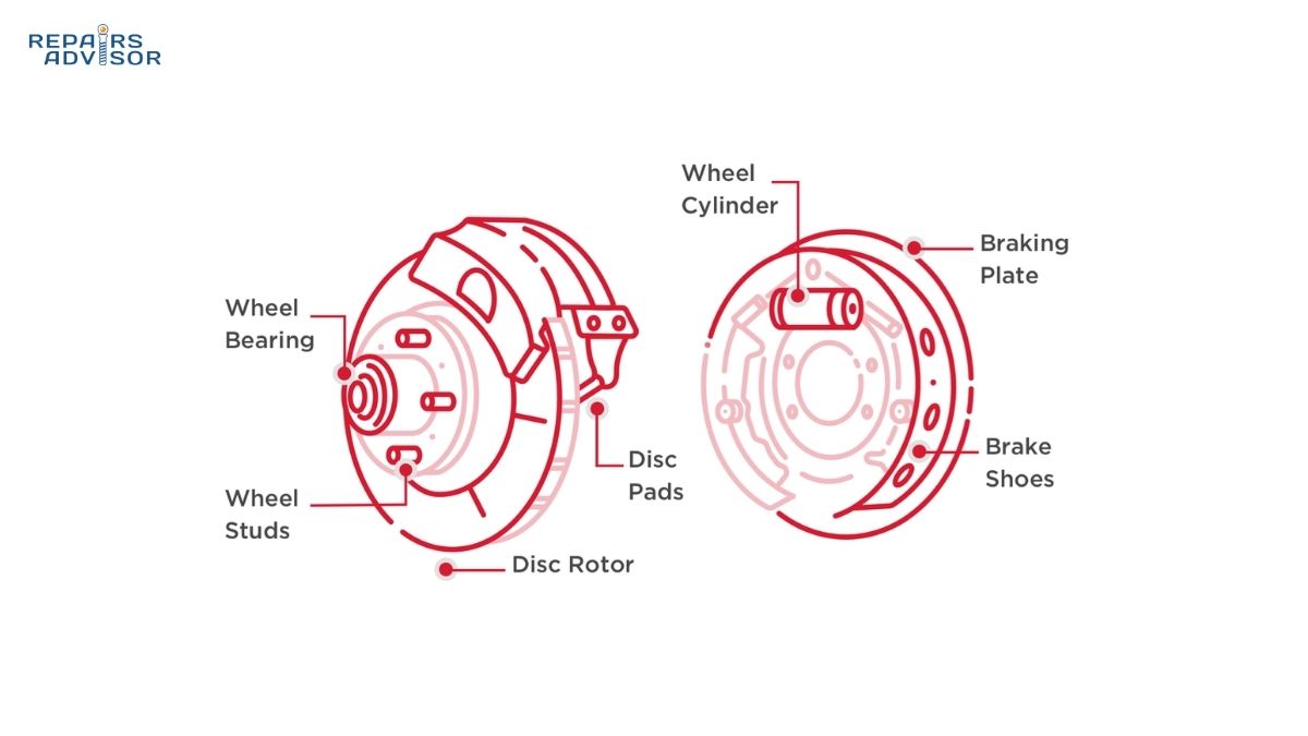
Brake calipers serve as the hydraulic clamps that convert fluid pressure into mechanical clamping force at each wheel. These precision-machined aluminum or cast iron housings contain one or more pistons that push brake pads against the spinning rotor when hydraulic pressure arrives. Caliper design varies significantly between vehicle types and applications, with two main categories: floating calipers that use a single piston and slide mechanism, and fixed calipers that employ multiple pistons on both sides of the rotor. We’ll examine these designs in detail in the next section. Calipers also house hydraulic seals, dust boots to protect piston surfaces, and bleeder valves for air purging during service. Quality calipers feature corrosion-resistant coatings, precise piston bore machining, and seals engineered to function through hundreds of thousands of brake applications over 5 to 10 years of service.
Brake rotors, also called brake discs, are the round cast iron or composite discs that spin with your wheels and provide the friction surface for brake pad contact. These seemingly simple components face extraordinary engineering challenges—they must maintain dimensional stability while cycling between ambient temperature and 1,200°F multiple times per drive, dissipate massive heat energy, resist warping from uneven cooling, and maintain a consistent friction surface through thousands of brake applications. Rotor design varies from simple solid discs for light-duty applications to complex vented, drilled, and slotted designs for performance and heavy-duty use. Rotor diameter typically ranges from 9 inches on small economy cars to 15 inches or larger on performance vehicles and trucks, with larger diameters providing greater mechanical leverage and better heat dissipation. The rotor has a minimum thickness specification stamped on its surface—once wear reduces thickness below this critical dimension, the rotor lacks sufficient thermal mass to safely dissipate heat and must be replaced.
Brake pads are the sacrificial friction elements that press against the rotor to create the friction that slows your vehicle. Each caliper holds two pads—one on each side of the rotor—consisting of a steel backing plate bonded to a carefully formulated friction material. The friction material composition dramatically affects pad performance, with organic, semi-metallic, and ceramic compounds each offering distinct advantages and tradeoffs in noise, dust, longevity, and performance. Brake pads incorporate wear indicators—either mechanical tabs that contact the rotor to create squealing noise when pads reach minimum thickness, or electronic sensors that illuminate a dashboard warning light. Fresh pads typically measure 10 to 12 millimeters thick; replacement becomes necessary when thickness drops to 3 millimeters or less. Quality brake pads feature precise dimensional tolerances, appropriate friction material for the application, and proper backing plate design to minimize noise and vibration.
Brake fluid serves as the hydraulic medium that transmits force through the brake system while also lubricating moving components and preventing corrosion. This specialized fluid faces extreme operating conditions—it must remain liquid and function from -40°F winter starts to over 400°F near the brakes during hard use, resist compression to maintain solid pedal feel, and protect metal components from corrosion. Most passenger vehicles use DOT 3 or DOT 4 glycol-ether brake fluid, with high-performance applications requiring DOT 5.1 for its higher boiling point. These fluids are hygroscopic, meaning they naturally absorb moisture from the atmosphere over time. As moisture content increases from fresh fluid (0.5% water) to old fluid (3% water or more), the boiling point drops dramatically—potentially 150°F or more. If brake fluid boils during hard braking, it creates vapor bubbles that compress under pressure, resulting in a soft, spongy pedal and dramatically reduced braking effectiveness. This is why brake fluid must be replaced every 2 to 3 years regardless of mileage. Learn more in our guide How Brake Fluid Works: Hydraulic Force Transmission.
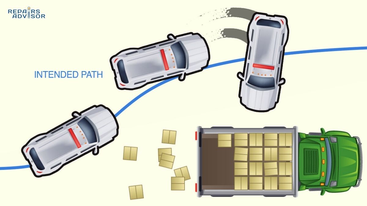
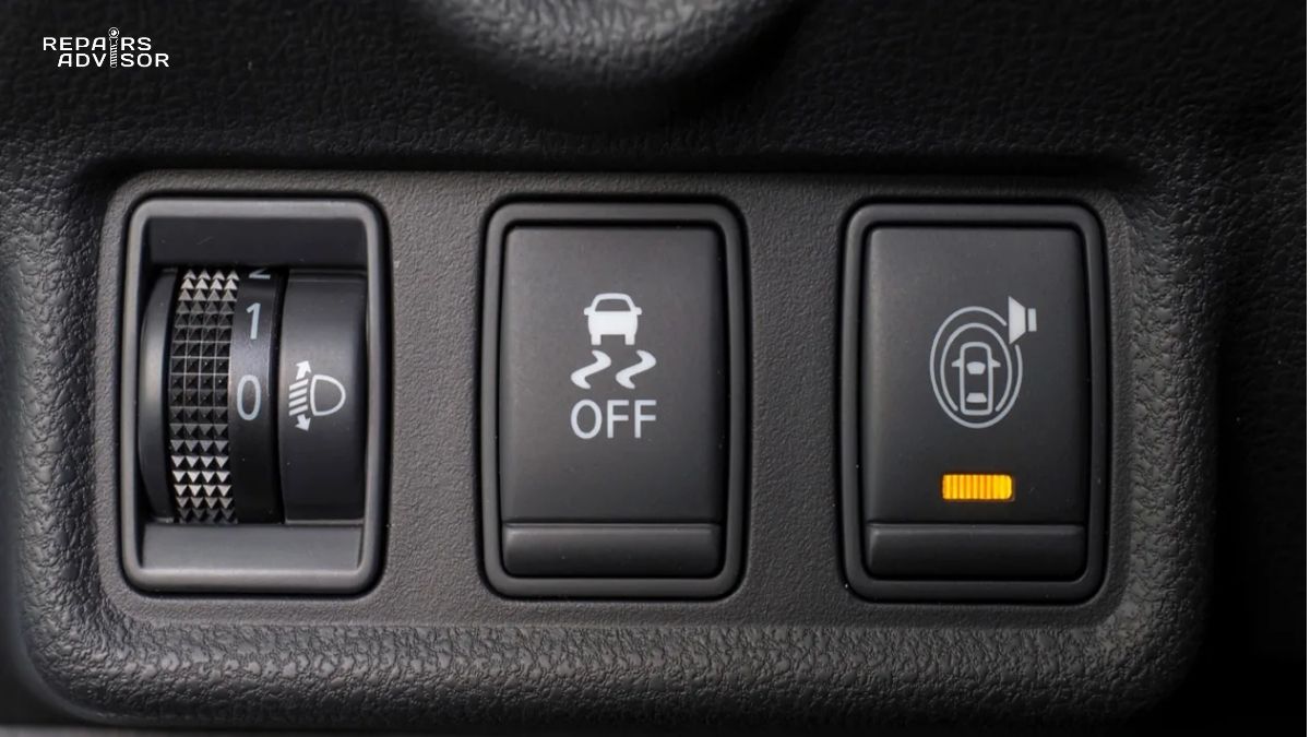
Electronic control systems integrate with disc brake systems on modern vehicles, adding layers of safety and capability beyond basic hydraulic braking. The Anti-lock Braking System (ABS) uses wheel speed sensors and a hydraulic control module to prevent wheel lockup during panic stops, maintaining steering control while maximizing stopping performance. Traction control systems use the same components to apply individual wheel braking to reduce wheel spin during acceleration on slippery surfaces. Electronic Stability Control (ESC) takes this further by using selective braking to help maintain vehicle stability during emergency maneuvers or when the driver loses control. These systems can pulse brake pressure 15 to 20 times per second at individual wheels—far faster than any human could modulate the brake pedal. Advanced driver assistance features like automatic emergency braking, adaptive cruise control, and hill hold function all depend on electronic brake system control. For detailed coverage of these technologies, see How ABS Systems Work: Anti-Lock Braking Technology.
Brake Caliper Types and Design Variations
Brake caliper design represents one of the most significant engineering decisions in a vehicle’s brake system, fundamentally affecting braking performance, cost, weight, and maintenance requirements. The two primary caliper architectures—floating and fixed—take completely different approaches to generating the clamping force that presses brake pads against rotors. Understanding these designs helps you appreciate why different vehicles have different brake characteristics, why some calipers are more expensive to replace than others, and how caliper choice affects everything from brake feel to fade resistance.
Floating calipers, also called sliding calipers, dominate passenger vehicle applications due to their simple, cost-effective design. These calipers employ a single large piston—typically 1.75 to 2.5 inches in diameter—mounted on the inboard side of the caliper body only. The caliper body itself mounts to a bracket via guide pins or slides that allow lateral movement. When you apply the brakes, hydraulic pressure pushes the piston outward, pressing the inboard brake pad against the inboard rotor surface. Here’s where the clever engineering comes in: as the piston extends, it pushes not just the pad but also generates an equal and opposite reaction force against the caliper body itself. Since the caliper body can slide on its guide pins, this reaction force pulls the entire caliper inward, drawing the outboard pad against the outboard rotor surface. The result is clamping action on both sides of the rotor despite having only a single piston.
The advantages of floating caliper design explain their widespread use on economy cars, mid-size sedans, and light-duty trucks. Manufacturing costs run significantly lower than fixed calipers due to simpler construction and fewer components—one piston assembly instead of four or six, less complex internal machining, and a smaller overall caliper body. The compact design allows fitment behind smaller diameter wheels, an important consideration for vehicles using 15 to 17-inch wheels. Service and replacement procedures are generally straightforward, with caliper removal often requiring just two bolts. Weight savings of 2 to 4 pounds per caliper compared to fixed designs benefit unsprung weight and handling. For typical daily driving conditions—commuting, city traffic, moderate highway use—floating calipers provide entirely adequate performance with proper maintenance.
However, floating calipers do have inherent limitations and maintenance requirements. The guide pins or slides that allow caliper movement require regular lubrication with high-temperature brake grease to maintain smooth operation. In regions with heavy road salt use or in vehicles that see infrequent use, these slide mechanisms can corrode and seize, preventing proper caliper movement. A seized floating caliper results in uneven pad wear—the piston-side pad wears more rapidly while the slide-side pad barely contacts the rotor. Guide pin seizure also causes brake drag where the caliper fails to properly retract, keeping pads in light contact with the rotor. This generates heat, causes premature wear, and reduces fuel economy. The single-piston design also means pressure distribution across the pad isn’t perfectly uniform, with the area directly opposite the piston receiving maximum pressure while pad edges receive less. Under sustained hard braking, this uneven pressure can contribute to faster fade compared to multi-piston designs.
Fixed calipers take a fundamentally different engineering approach, using multiple pistons arranged on both sides of the rotor with a rigid caliper body that doesn’t move. Common configurations include 2-piston (one per side), 4-piston (two per side), 6-piston (three per side), and even 8-piston (four per side) layouts. When hydraulic pressure arrives, all pistons receive the same pressure simultaneously and push their respective pads toward the rotor from both sides. This symmetrical pressure application provides several performance advantages: more even pressure distribution across the entire pad surface, better heat dissipation through the larger caliper body mass, superior fade resistance during sustained hard braking, and more consistent pad wear patterns. The rigid mounting eliminates slide pins and their maintenance issues, while the balanced piston arrangement produces excellent brake pedal feel and response.
Fixed caliper applications reflect their performance advantages and higher cost. Sports cars and performance sedans use fixed calipers to handle repeated hard stops on winding roads or track days without brake fade. Heavy-duty trucks employ them to manage the extreme heat generated when stopping heavy loads or descending mountain grades. High-end luxury vehicles specify fixed calipers for their refined feel and consistent performance. Aftermarket performance brake upgrades almost always involve replacing floating calipers with fixed multi-piston designs. The drawbacks include significantly higher manufacturing cost—often 2 to 3 times a comparable floating caliper—and increased weight that adds to unsprung mass. The larger physical dimensions can create wheel clearance issues, sometimes requiring larger diameter wheels to fit over the bigger calipers. Brake fluid bleeding becomes more complex with multiple pistons, and seal replacement during caliper rebuilds involves more labor.
Piston material selection represents another engineering consideration that affects brake system behavior. Traditional steel pistons offer excellent durability and dimensional stability but conduct heat effectively, transferring rotor heat into the brake fluid. Over time and with hard use, this heat transfer can raise fluid temperature enough to reduce the effective boiling point. Aluminum pistons dissipate heat better than steel, helping protect fluid temperature, but require hard anodizing to prevent corrosion and provide a suitable seal surface. Phenolic resin pistons, made from heat-resistant composite material, provide excellent thermal insulation to minimize heat transfer to brake fluid. However, phenolic pistons are less robust than metal and can be more prone to damage during service if compressed unevenly. Many modern calipers use a combination—phenolic pistons for the higher-temperature inboard position and aluminum for the cooler outboard position.
The square-section piston seals that seal each piston in its bore perform a remarkable dual function in brake system operation. Beyond preventing fluid leaks, these seals actually provide the mechanism for pad retraction when you release the brakes. During brake application, hydraulic pressure forces the piston outward, stretching the elastic seal slightly. When pressure releases, the seal elastically returns to its original shape, pulling the piston back approximately 0.005 to 0.010 inches—just enough to create clearance so pads don’t drag against the rotor, but maintaining minimal clearance for instant response when you apply brakes again. This elegant design eliminates the need for return springs and ensures proper pad clearance throughout the brake pad’s life. Seal quality and proper lubrication of the piston bore during installation critically affect long-term caliper reliability.
Brake Rotor Design and Engineering
Brake rotors might appear to be simple cast iron discs, but they represent sophisticated metallurgical and mechanical engineering designed to reliably handle one of the most demanding thermal and mechanical environments in your vehicle. Every time you brake, rotors must absorb and dissipate massive thermal energy while maintaining dimensional stability, resist warping from uneven heating and cooling, provide consistent friction surface to the brake pads, and survive corrosive road salt exposure—all while spinning at wheel speed with minimal runout. Rotor design variations address different performance requirements, from basic transportation to high-performance driving to heavy-duty commercial applications.
Solid rotors represent the most basic and economical design, consisting of a single cast iron disc typically 8 to 12 millimeters thick. The entire disc is solid metal without internal venting or cooling passages. This simple construction keeps costs low and works adequately for applications with modest braking demands—rear axles of lighter vehicles, small economy cars, and vehicles used primarily for city driving. Solid rotors have significant limitations in heat dissipation capacity. During repeated braking, the entire rotor mass heats up uniformly with limited surface area to shed heat to passing air. Under sustained use like mountain descents or repeated highway stops, solid rotors can experience brake fade as temperatures climb beyond optimal operating range. Most modern vehicles use solid rotors only on rear axles where braking loads are lower—rear brakes typically provide only 30 to 40 percent of total braking force due to forward weight transfer during stopping.
Vented rotors employ a two-piece construction with two friction surfaces separated by internal cooling vanes, creating a design that looks like two discs joined by fins when viewed from the side. This architecture dramatically improves heat dissipation through multiple mechanisms. First, the internal vanes create air channels that pump cooling air through the rotor as it spins, acting like a centrifugal fan. Second, the doubled surface area—two friction surfaces plus all the vane surfaces—provides more area for heat to radiate to the surrounding air. Third, the air gap between the two faces provides some thermal isolation preventing heat from one side immediately conducting to the other side. Vented rotors typically measure 20 to 32 millimeters thick and weigh 15 to 25 pounds for passenger car applications. The vane design varies considerably—straight radial vanes are simplest and least expensive, curved or directional vanes optimize airflow for better cooling, and pillar-style vanes improve structural rigidity. Most modern vehicles over 3,000 pounds use vented rotors on the front axle as standard equipment due to the heavy thermal loads from repeated braking.
Drilled rotors feature holes drilled completely through the friction surface, a design with origins in racing but now popular in aftermarket street applications. The original engineering intent focused on allowing gases released from brake pad material at extreme temperatures to escape rather than forming a gas layer between pad and rotor. Modern brake pad formulations release far less gas than vintage materials, making this benefit less relevant for street driving. Drilling does provide some advantages: the holes offer marginal additional cooling surface area, they help disperse water in wet conditions allowing pads to maintain better contact, and they undeniably look aggressive and performance-oriented behind open wheel designs. However, drilling creates stress concentration points around each hole that make rotors more susceptible to cracking under extreme thermal cycling or sustained hard use. Race teams using drilled rotors typically replace them frequently as consumables. For street use, high-quality drilled rotors with chamfered hole edges reduce stress concentration, but the design remains less structurally robust than un-drilled alternatives. Most brake engineers consider drilling more of an aesthetic choice than a functional performance advantage for street-driven vehicles.
Slotted rotors feature shallow grooves machined into the friction surface, typically 0.5 to 1.5 millimeters deep running in various patterns across the rotor face. Unlike drilling, slotting doesn’t compromise structural integrity since the grooves don’t penetrate through the rotor. Slots serve several useful functions: they continuously scrape the pad surface, removing glazing, embedded debris, and the thin transfer layer that forms between pad and rotor. This “re-facing” action maintains more consistent friction characteristics throughout the pad’s life. Slots also provide escape routes for gases, water, and debris, preventing buildup between pad and rotor. For high-performance and track applications, slotted rotors demonstrably maintain more consistent friction coefficient during sustained hard use compared to smooth rotors. The tradeoff is slightly accelerated pad wear since the slot edges create a mild cutting action on the pad material. Most brake pad compounds can handle this additional wear without problems. Professional race teams and serious track-day enthusiasts often prefer slotted designs over drilled for their combination of performance benefits and structural reliability.
Combination drilled and slotted rotors attempt to capture benefits of both designs in one rotor. These are popular in the aftermarket performance and sport truck segments where both performance and appearance matter to buyers. The slots provide the functional friction-maintenance benefits while drilling adds visual impact and some additional cooling surface. Quality examples use properly chamfered drilled holes to minimize stress concentration. For street performance applications and moderate track use, combination rotors can work well, though the drilling still represents a structural compromise versus slotted-only designs. The significant premium pricing compared to standard vented rotors—often 2 to 3 times the cost—should make buyers carefully consider whether their driving actually demands the additional capability or whether aesthetics drive the purchase decision.
Rotor metallurgy and quality variations significantly affect performance and longevity. Standard gray cast iron contains graphite in the iron matrix, providing good machining characteristics, appropriate friction surface hardness (typically 200 to 250 Brinell), and acceptable thermal properties at moderate cost. Premium rotors use high-carbon cast iron with improved heat dissipation and fade resistance, typically found on performance vehicles or offered as aftermarket upgrades. Exotic materials like carbon-ceramic composites offer extraordinary heat resistance and weight savings but cost thousands of dollars per rotor—reserved for supercars and high-end sports cars. Two-piece rotors use an aluminum center hat with an iron friction ring, saving considerable weight while maintaining proper friction characteristics. Quality considerations matter significantly: premium rotors from manufacturers like Brembo, ATE, and Bosch feature precision machining, proper heat treatment, and protective coatings. Budget rotors may have rougher friction surfaces, inferior metallurgy that warps more easily, and minimal corrosion protection that leads to rust issues.
Critical rotor specifications that affect brake system function include minimum thickness—stamped on the rotor and representing the thinnest dimension at which the rotor safely manages heat and maintains structural integrity; runout tolerance, typically 0.002 to 0.003 inches, measuring how much the rotor wobbles as it rotates; thickness variation, which must remain within 0.0005 inches across the entire friction surface to prevent pedal pulsation; and diameter, which ranges from 9 inches on small economy cars to 15 inches or larger on performance and heavy-duty vehicles. Larger diameter provides both greater mechanical leverage (more braking torque for given clamping force) and more friction surface area to dissipate heat. Understanding these specifications helps when making rotor replacement or upgrade decisions.
Brake Pad Materials and Friction Characteristics
Brake pad material selection represents one of the most consequential decisions in brake system design and maintenance, fundamentally affecting stopping distance, brake feel, noise levels, dust production, longevity, and cost. The friction material bonded to each pad’s steel backing plate must generate consistent, predictable friction against the rotor across a wide temperature range while withstanding extreme conditions—repeated heating to 600°F or higher, exposure to water and road salt, constant vibration, and mechanical stress from thousands of brake applications. Three primary pad material families dominate modern applications: organic (also called Non-Asbestos Organic or NAO), semi-metallic, and ceramic. Each offers distinct advantages and tradeoffs that make them optimal for different driving conditions and priorities.
Organic brake pads use a mixture of organic fibers, rubber, glass or carbon fibers, and resin binders to create the friction material. These represent the softest and most compliant of the three main pad types, typically containing 10 to 30 percent metal content by weight. The soft composition produces several beneficial characteristics: organic pads operate very quietly with minimal squealing or noise, they’re extremely gentle on rotors causing minimal rotor wear, and they exhibit excellent “cold bite”—effective friction immediately even when completely cold. This makes organic pads ideal for the first stop of the morning when other pad types might feel less responsive. Temperature operating range spans approximately 0 to 300°F, well-suited for normal daily driving conditions. Organic pads produce the least brake dust of any pad type, keeping wheels cleaner longer—an aesthetic advantage appreciated by car enthusiasts who detail their vehicles.
The limitations of organic pad materials become apparent under demanding conditions. Operating temperatures above 300°F sustained cause organic materials to begin breaking down and losing friction capability—a phenomenon called brake fade. Even more concerning, overheating can cause organic pads to glaze, where the surface hardens into a shiny, slick finish that permanently reduces friction capability until the pad is replaced or resurfaced. The soft material composition results in the shortest lifespan of any pad type, typically 30,000 to 40,000 miles depending on driving style. The higher compressibility of organic materials produces a softer, spongier brake pedal feel compared to harder pad materials. These characteristics make organic pads poorly suited for towing, sustained mountain driving, or performance applications. They work best for lighter vehicles under 3,000 pounds, urban commuting, and drivers who prioritize quiet operation and minimal maintenance over ultimate performance.
Semi-metallic brake pads contain 30 to 65 percent metal content by weight—typically steel and iron fibers mixed with copper, graphite lubricant, friction modifiers, and resin binders. This significantly harder composition produces brake pads with different performance characteristics better suited to demanding applications. Semi-metallic pads exhibit excellent heat resistance with effective operation up to 600 to 700°F sustained temperatures, far beyond organic capabilities. They maintain better cold bite than ceramic pads, nearly matching organic pad initial responsiveness. Fade resistance remains strong even during sustained hard braking—exactly what’s needed when towing heavy trailers down mountain grades or during spirited driving on winding roads. Longevity typically extends to 50,000 to 70,000 miles, roughly 50 percent longer than organic pads. The combination of good heat handling, decent cold performance, long life, and moderate pricing makes semi-metallic pads the most versatile choice across various driving conditions.
Semi-metallic pads do have notable drawbacks. Noise production runs higher than other pad types, with more frequent squealing especially when cold or in wet conditions. The harder composition generates 20 to 30 percent more rotor wear compared to organic pads, shortening rotor life. Brake dust production exceeds organic pads, and the metallic dust tends to be more abrasive and prone to staining wheel finishes if not cleaned regularly. Some drivers find the brake feel less refined than ceramic pads. Despite these compromises, semi-metallic pads remain the preferred choice for trucks, SUVs, performance vehicles, and any application involving towing, frequent highway driving, or mountain terrain. The superior thermal performance and fade resistance provide important safety margins during demanding braking situations.
Ceramic brake pads use a dense ceramic compound matrix with fine copper fibers embedded throughout. The material resembles pottery ceramic but with substantially greater density and durability. Ceramic pads were developed as a premium alternative attempting to match semi-metallic durability and heat handling while approaching organic-level noise and cleanliness. The results are impressive: ceramic pads operate even more quietly than organic pads, producing the least noise of any pad type across all conditions. Brake dust production is minimal, and the fine, light-colored dust that does form doesn’t adhere aggressively to wheels, making cleanup easier. Longevity typically reaches 60,000 to 80,000 miles, providing the longest service life of any pad type. Performance consistency across a wide temperature range—from cold weather starts to sustained highway braking—remains excellent.
However, ceramic pads aren’t universally superior and have specific weaknesses. Cost runs 20 to 40 percent higher than comparable semi-metallic pads, making them the most expensive option. Cold bite—initial friction when completely cold—lags behind organic and semi-metallic pads, which can feel concerning to drivers in very cold climates (below 20°F). The ceramic material acts more as a thermal insulator than conductor, meaning heat generated stays in the rotor and surrounding brake components rather than being absorbed by the pad. In extreme use scenarios, this can lead to higher overall brake system temperatures despite the pads themselves handling heat well. Track-focused driving or racing applications generally avoid ceramic pads for these thermal characteristics, preferring semi-metallic or specialized race compounds. For luxury vehicle daily driving where quiet operation, minimal maintenance, and long life are priorities, ceramic pads excel. Learn more about friction material engineering in How Brake Pads & Rotors Work: Friction and Heat Management.
Selecting the right pad material for your specific situation requires honest assessment of your driving patterns, vehicle type, and priorities. Choose organic pads if you drive a light vehicle under 3,000 pounds, rarely tow or carry heavy loads, prioritize the quietest possible operation, and want to minimize costs despite shorter lifespan. These work well for urban commuters who drive shorter distances and rarely demand high braking performance. Choose semi-metallic pads if you tow trailers or haul heavy loads regularly, drive a truck, SUV, or performance vehicle, live in mountainous terrain requiring sustained braking, prioritize maximum performance over noise and dust considerations, or want the best overall value balancing performance and cost. Semi-metallic remains the most versatile choice for drivers who occasionally need heavy-duty braking capability. Choose ceramic pads if you want the longest possible pad life and minimal maintenance, prioritize quiet operation and clean wheels, drive a luxury vehicle where refinement matters, have the budget for premium pricing, and drive primarily in moderate conditions without extreme performance demands. No single pad type is universally “best”—optimal choice depends on matching characteristics to your specific needs.
Hydraulic System Operation and Brake Fluid
The hydraulic brake system represents one of the most elegant applications of fluid mechanics in automotive engineering, using incompressible liquid to instantly transmit and multiply force from the driver’s foot to brakes at all four wheels simultaneously. Understanding hydraulic principles explains how your moderate pedal pressure generates massive clamping forces while maintaining precise control over braking intensity. The system also demonstrates clever engineering in its built-in safety redundancy and the critical role brake fluid plays beyond simply transmitting pressure.
Pascal’s Law forms the foundation of hydraulic brake operation, stating that pressure applied to a confined fluid transmits equally in all directions throughout the fluid. When the master cylinder piston pressurizes brake fluid, that pressure instantly propagates through all the brake lines to every caliper at every wheel, regardless of line length or routing. More importantly, hydraulic systems allow force multiplication through piston area differences. Consider a simplified example: if the master cylinder piston has 1 square inch of area and the brake caliper piston has 2 square inches of area, hydraulic pressure created by 100 pounds of force on the master cylinder piston will generate 200 pounds of force at the caliper piston. The pressure remains constant (100 PSI in this example), but the larger caliper piston experiences greater total force due to its greater area. Real brake systems use this principle with typical force multiplication of 4 to 6 times between master cylinder and calipers. Combined with the 4 to 6 times mechanical advantage from the brake pedal lever and the 3 to 5 times amplification from the brake booster, total system force multiplication reaches 15 to 20 times or more. This explains how your 50-pound foot pressure becomes 800 to 1,000 pounds of clamping force at each wheel.
Modern master cylinders use tandem design with two independent pistons creating two separate hydraulic circuits—a critical safety feature mandated since the 1960s. The primary piston connects directly to the brake booster pushrod and pressurizes the primary circuit. Behind it, the secondary piston pressurizes the secondary circuit. If either circuit develops a leak—from a failed caliper, broken brake line, or any other cause—the other circuit maintains independent operation. Circuit design typically uses diagonal split where one circuit operates the left-front and right-rear brakes while the other operates the right-front and left-rear brakes. This configuration ensures that even with complete single-circuit failure, you retain braking on one front wheel (where most braking force is needed) and the opposite rear wheel, maintaining some steering control while stopping. The master cylinder incorporates compensation ports that open when the brake pedal fully releases, allowing fluid to return to the reservoir and preventing pressure buildup as pads wear and caliper pistons extend. Some master cylinders include residual pressure valves that maintain slight positive pressure (typically 2 to 10 PSI) in the lines to prevent air from entering through seals and to maintain instant brake response.
Brake fluid serves multiple critical functions beyond transmitting hydraulic pressure. It must lubricate all moving parts within the hydraulic system—master cylinder pistons, caliper pistons, proportioning valve internals, and ABS pump components. The fluid must protect ferrous metal brake system components from corrosion over many years of service. Crucially, brake fluid must maintain low compressibility across extreme temperatures—if the fluid compresses significantly under pressure, brake pedal feel becomes soft and mushy. Operating temperature range spans from -40°F during winter cold starts to over 400°F in brake calipers during hard use, requiring remarkable fluid stability. The single most critical property is boiling point—if brake fluid boils, it creates vapor bubbles that are highly compressible, resulting in dramatically reduced braking performance or complete brake failure.
DOT 3 brake fluid represents the most common specification for passenger vehicles, using glycol-ether chemical base with friction modifiers and corrosion inhibitors. Fresh DOT 3 has a dry boiling point of 401°F—the temperature at which it boils when containing zero moisture. The wet boiling point of 284°F represents boiling temperature after the fluid has absorbed 3.7 percent water by weight. Since glycol-ether brake fluids are hygroscopic (naturally absorb atmospheric moisture), the wet boiling point is more relevant for fluid in service. DOT 3 provides adequate performance for most passenger vehicles with normal driving patterns. Typical change interval recommendations range from 2 to 3 years regardless of mileage.
DOT 4 brake fluid uses enhanced glycol-ether formulation with borate esters that provide higher boiling points: 446°F dry and 311°F wet. The improved thermal performance makes DOT 4 better suited for vehicles used in demanding conditions—frequent towing, mountain driving, heavier vehicles, or spirited performance driving. DOT 4 absorbs moisture slightly faster than DOT 3 due to its chemical composition, so regular replacement remains important. The moderate cost premium over DOT 3 (typically 20 to 30 percent) makes DOT 4 a worthwhile upgrade for drivers who frequently stress their brake systems.
DOT 5.1 brake fluid offers the highest performance of glycol-ether formulations, with dry boiling point of 500°F and wet boiling point of 356°F. Unlike DOT 5 silicone fluid, DOT 5.1 remains fully compatible with DOT 3 and DOT 4 systems since it uses the same glycol-ether base chemistry. This makes DOT 5.1 suitable for high-performance vehicles, track driving, racing applications, and any situation where brake temperatures may reach extreme levels. Premium pricing limits its use primarily to enthusiast and professional applications.
DOT 5 silicone brake fluid represents a completely different chemistry—silicone-based rather than glycol-ether. It does not absorb moisture (non-hygroscopic), making it attractive for military vehicles and collector cars stored long periods. However, DOT 5 has significant drawbacks that prevent widespread use: it’s more compressible than glycol fluids, producing softer, less precise pedal feel; it’s not compatible with most modern ABS systems; and it absolutely cannot be mixed with DOT 3/4/5.1 fluids—doing so causes fluid breakdown and brake system damage. Unless you’re maintaining a classic car or military vehicle specifically designed for DOT 5, stick with glycol-ether fluids.
The hygroscopic nature of glycol-ether brake fluids (DOT 3/4/5.1) means they naturally absorb moisture from atmospheric humidity. Fresh fluid starts near 0 percent water content, but exposure to atmosphere during brake bleeding, minor leaks allowing air entry, and permeation through rubber hoses gradually increase moisture content. Typical absorption rates add 2 to 3 percent water annually. This matters enormously because dissolved water dramatically lowers boiling point—fresh DOT 3 with 401°F dry boiling point drops to 284°F wet boiling point at just 3.7 percent water. Old brake fluid with 5 percent water might boil at 250°F or lower, well within temperatures reached during hard mountain descent or repeated highway stops. When brake fluid boils, vapor bubbles form that compress when you press the pedal, causing soft, spongy pedal feel and greatly reduced stopping ability—a dangerous situation. This is why brake fluid must be replaced on a time schedule (every 2 to 3 years) rather than waiting for specific mileage or visible contamination.
Complete brake fluid flush involves removing all old fluid from the master cylinder reservoir, brake lines, ABS module (if equipped), and all four calipers, replacing it with fresh fluid. Professional shops use pressure or vacuum bleeding equipment that makes the process faster and more thorough than traditional two-person manual bleeding. The service includes bleeding in proper sequence (usually starting from wheel farthest from master cylinder), purging air from the system, and verifying firm pedal feel. ABS-equipped vehicles may require scan tool activation to cycle the ABS pump and valves during bleeding, ensuring fluid reaches all internal ABS module passages. While DIY bleeding is possible, the specialized equipment and technique requirements make professional service advisable for most vehicle owners. The cost (typically $80 to 150) is modest compared to the safety criticality of proper brake system function.
How Disc Brake Systems Operate Step-by-Step
Understanding the complete sequence of events from the moment you touch the brake pedal to the friction at each wheel reveals the sophisticated choreography of mechanical, hydraulic, and electronic systems working in precise coordination. This step-by-step breakdown explains what happens during a typical brake application, illustrating how each component contributes to safe, controlled vehicle deceleration.
When you press the brake pedal with typical pedal force of 30 to 60 pounds, the brake pedal lever mechanism immediately multiplies this input through mechanical advantage. Most brake pedal assemblies employ a lever ratio between 4:1 and 6:1, meaning your 50-pound foot pressure becomes 200 to 300 pounds of force transmitted through the pedal’s pivot point to the pushrod. The pushrod extends forward from the pedal assembly through the brake booster to contact the master cylinder piston. This mechanical linkage also activates the brake light switch, illuminating your stop lamps to warn following traffic, and signals the engine control module that braking is occurring, allowing the ECM to optimize fuel delivery and transmission behavior.
The brake booster provides the second critical stage of force amplification. In vacuum-assisted boosters (most common), engine intake manifold vacuum creates low pressure in a chamber on one side of a rubber diaphragm. When you press the brake pedal, a control valve opens atmospheric pressure to the other side of the diaphragm. The pressure differential across the large diaphragm area (typically 8 to 10 inches in diameter) generates significant force—a multiplication factor of 3 to 5 times the pushrod input. Your initial 200 to 300 pounds from the pedal becomes 600 to 1,500 pounds applied to the master cylinder piston. Electric brake boosters achieve similar multiplication using an electric motor and gearbox rather than vacuum. Without booster assistance, you’d need to apply extreme leg force to achieve the same braking effect—you can experience this by attempting to brake with the engine off, which provides no vacuum assist.
The master cylinder converts this mechanical force into hydraulic pressure throughout the brake system. As the master cylinder’s primary piston moves forward in its bore, it pressurizes brake fluid in front of it. This pressure closes the compensation ports, preventing fluid from returning to the reservoir, and forces the secondary piston forward, pressurizing the secondary circuit as well. Typical hydraulic pressures during moderate braking reach 800 to 1,200 PSI, while emergency stops can generate up to 2,000 PSI. This pressure instantly transmits through all brake lines to each wheel’s caliper since hydraulic fluid is essentially incompressible. The tandem master cylinder design ensures that both brake circuits receive pressure simultaneously—one circuit typically feeds the left-front and right-rear brakes while the other feeds the right-front and left-rear brakes in diagonal-split systems.
Hydraulic force distributes through the brake lines and hoses to all four wheels simultaneously, but not necessarily with equal pressure at front and rear axles. Most vehicles incorporate a proportioning valve or load-sensing proportioning valve that reduces rear brake pressure by 20 to 30 percent compared to front pressure. This prevents rear wheel lockup during hard braking when weight transfer loads the front axle heavily while unloading the rear. Without proper proportioning, rear wheels would lock first during panic stops, causing loss of directional stability and potential spin. Modern vehicles with ABS use the electronic control module to manage front/rear brake balance dynamically rather than relying on fixed mechanical proportioning. For more on this system, see How Brake Proportioning Valves Work: Force Distribution.
At each wheel’s caliper, hydraulic pressure acts on the piston or pistons to generate the mechanical clamping force. In floating calipers, pressure behind the single inboard piston forces it outward against its seal resistance. The piston extends, pushing the inboard brake pad into firm contact with the inboard rotor surface. Simultaneously, the reaction force from the piston pushing against the pad and rotor causes the entire caliper body to slide inward on its guide pins, pulling the outboard pad into contact with the outboard rotor surface. Fixed calipers work differently—pressure reaches pistons on both sides of the rotor simultaneously through internal fluid passages, and opposing pistons extend toward each other, pressing both pads against their respective rotor surfaces. The square-section rubber seals that surround each piston allow the piston to extend while maintaining hydraulic seal integrity.
Once both pads contact the spinning rotor with sufficient force, friction begins converting the vehicle’s kinetic energy into thermal energy. The friction coefficient between brake pad material and rotor surface typically ranges from 0.35 to 0.45, meaning the friction force equals 35 to 45 percent of the clamping force pressing the pads against the rotor. With hydraulic pressure creating 1,000 to 2,000 pounds of clamping force per caliper and friction coefficient around 0.40, each wheel generates 400 to 800 pounds of braking force. Multiply this by four wheels, and total vehicle braking force reaches 1,600 to 3,200 pounds or more—sufficient to decelerate a 4,000-pound vehicle at over 0.8g, the threshold for activating ABS on most surfaces.
The friction process generates substantial heat as kinetic energy converts to thermal energy. During normal braking, rotor temperatures climb from ambient to 200 to 400°F at the friction surface. Aggressive braking or sustained mountain descents can push temperatures to 800 to 1,200°F or even higher. Brake system design must manage this thermal load—vented rotors pump cooling air through their internal passages, brake pads use high-temperature binders that maintain friction even when hot, and calipers use heat-resistant seals and dust boots. Heat transfer from rotors to hubs, wheel bearings, and other nearby components requires careful thermal management to prevent damage. Excessive heat causes brake fade where pad friction coefficient drops or brake fluid approaches its boiling point, reducing braking effectiveness until components cool.
Throughout the braking process, you maintain precise control over deceleration rate by modulating brake pedal pressure. The hydraulic system responds essentially instantaneously to pressure changes—there’s no lag or delay between pedal adjustment and brake force change at the wheels. This precise, progressive control allows smooth, comfortable stops and the ability to threshold brake just short of wheel lockup in emergency situations. On vehicles equipped with ABS, if wheel speed sensors detect any wheel beginning to lock up (rotating significantly slower than vehicle speed would indicate), the ABS control module commands solenoid valves to pulse pressure to that wheel’s brake, releasing and reapplying pressure 15 to 20 times per second. This prevents wheel lockup while maintaining maximum braking force and preserving steering control.
When you release brake pedal pressure, the master cylinder pistons retract and open the compensation ports, allowing pressurized fluid to flow back to the reservoir. Hydraulic pressure throughout the system drops to zero. At each caliper, the square-section piston seals—which were stretched slightly outward during brake application—now elastically return to their original shape, pulling the pistons back approximately 0.005 to 0.010 inches into their bores. This small retraction creates just enough clearance so the brake pads no longer contact the rotor, preventing brake drag and the associated heat buildup, pad wear, and fuel economy loss. In floating calipers, guide pin springs help center the caliper over the rotor. The system is now reset and ready for the next brake application with minimal pad-to-rotor clearance ensuring instant response.
Modern electronic integration adds layers of capability to this basic hydraulic operation. Traction control systems use individual wheel braking to reduce wheel spin during acceleration on slippery surfaces. Electronic Stability Control applies selective braking to individual wheels to help maintain vehicle stability during emergency maneuvers. Automatic emergency braking can activate the brake system without driver input when forward collision is imminent. Hill hold function maintains brake pressure after you’ve stopped on an incline, preventing rollback when you move your foot from brake to throttle. All these features rely on electronic control of the hydraulic brake system. For detailed coverage, see How Electronic Stability Control Works: Vehicle Dynamics Management.
Common Disc Brake Problems and Maintenance
Despite robust engineering and built-in redundancy, disc brake systems experience various problems over their service life. Recognizing symptoms early and understanding their causes helps prevent minor issues from escalating into safety hazards or expensive repairs. Regular maintenance following manufacturer schedules keeps brake systems functioning optimally and prevents many common problems.
Brake noise represents the most common brake complaint, manifesting in several distinct forms. Squealing or squeaking occurs as high-frequency vibration between brake pad and rotor surfaces. Light squeaking in the morning, especially after overnight moisture accumulation, is harmless and typically disappears after a few stops as pads and rotors dry. Persistent squealing indicates issues requiring attention: worn brake pads approaching minimum thickness often have built-in squealer tabs—small metal fingers that contact the rotor when pad material thins, intentionally creating noise to warn of needed replacement; glazed pad surfaces where overheating has hardened the friction material into a shiny, slick finish that squeals continuously; contamination of pad surfaces with oil, grease, or brake fluid that drastically alters friction characteristics; missing or damaged anti-rattle shims and clips that normally dampen vibration; or simply pad material characteristics—some harder compounds, especially semi-metallic, naturally generate more noise. While annoying, most squealing doesn’t indicate immediate safety concerns, but persistent noise warrants inspection.
Grinding noises represent a completely different situation demanding immediate attention. This metal-on-metal sound indicates brake pads worn completely through to their steel backing plates. The backing plate now contacts the rotor directly, causing rapid and expensive rotor damage. Grinding often accompanies pulsating brake pedal, visible scoring or grooves on rotor surfaces, and dramatically reduced stopping effectiveness. Continuing to drive with grinding brakes can destroy rotors, damage calipers, and create dangerous stopping distances. Most brake pad wear indicators are designed to squeal well before grinding occurs, providing advance warning. If you hear grinding, stop driving the vehicle and have it towed to a repair facility—the additional damage caused by each mile of driving significantly increases repair costs.
Groaning or moaning during light brake application typically stems from low-frequency vibration of brake components. This can result from pad material vibrating against the caliper bracket, incorrect pad compound choice for the application, lack of proper anti-squeal lubricant on pad backing plates and caliper contact points, or resonance through suspension components. While not typically indicating imminent failure, groaning degrades brake refinement and often worsens over time. The solution usually involves replacing pads with different material composition, proper lubrication of contact points with high-temperature brake grease, and installing or replacing anti-rattle hardware.
Brake fade describes reduced braking effectiveness that occurs during prolonged or repeated hard braking. Symptoms include brake pedal traveling farther than normal with less stopping force, need to pump the pedal to build pressure, and inability to maintain constant speed on downhill grades despite steady brake pressure. Brake fade has two primary causes: brake fluid reaching its boiling point creates compressible vapor bubbles in the hydraulic system—the soft, spongy pedal feel from vapor lock represents dangerous loss of braking power; and pad friction material exceeding its effective temperature range loses friction capability even though pads remain in contact with rotors. Prevention strategies include maintaining fresh brake fluid with appropriate DOT specification for your driving conditions, upgrading to higher-performance pad compounds if you regularly drive demanding conditions, considering upgraded rotors with better heat dissipation, using engine braking on long descents to reduce brake thermal load, and allowing cooling periods during sustained hard use. If you experience brake fade during mountain driving or towing, pull over safely and allow 15 to 20 minutes for brake system cooling before continuing.
Brake pedal problems provide critical diagnostic information about system condition. A soft or spongy pedal that requires more travel than normal and lacks firm feel typically indicates air in the hydraulic system, most commonly after recent brake service if bleeding wasn’t thorough. Other causes include brake fluid leaks reducing system pressure, internal master cylinder wear allowing pressure bypass, or flexible brake hoses expanding under pressure rather than transmitting it solidly to calipers. Proper brake bleeding following manufacturer procedures resolves air-related softness. Persistent soft pedal after proper bleeding indicates component failure requiring professional diagnosis.
Pedal pulsation or brake rotor pulsation presents as rhythmic variation in pedal resistance or vibration felt through the pedal and steering wheel during braking. The brake pedal seems to push back against your foot in pulses synchronized with wheel rotation. Root causes include excessive rotor thickness variation where one section of the rotor is thinner than another due to uneven wear, warped rotors from uneven heating and cooling, excessive rotor runout (wobble) from improper installation or hub damage, or wheel bearing problems causing rotor to wobble on its axis. Minor pulsation from slight thickness variation can sometimes be corrected by rotor resurfacing on a brake lathe, but modern thin rotors often can’t be machined without dropping below minimum thickness specification. Rotor replacement typically provides the best resolution. Preventing rotor warping involves avoiding aggressive braking immediately after driving through deep water (sudden cooling warps hot rotors), proper torque of wheel lug nuts in star pattern, and cleaning hub mounting surface thoroughly when installing new rotors.
Low brake pedal that travels nearly to the floor but eventually builds pressure indicates severely worn pads, automatic adjuster mechanism failure in drum brakes, or air in the system. If the pedal goes completely to the floor with little resistance, this represents a critical safety emergency: severe brake fluid leak, complete master cylinder failure, or catastrophic brake line failure. DO NOT DRIVE the vehicle—have it towed to a repair facility. Loss of primary or secondary hydraulic circuit also produces longer pedal travel as the remaining circuit struggles to generate adequate pressure.
Hard brake pedal requiring excessive force to achieve normal braking typically indicates brake booster failure. Vacuum-assisted boosters fail from vacuum line leaks, internal diaphragm rupture, or check valve malfunction. Electric boosters fail from motor or control module problems. Without booster assist, you must provide all the force through leg pressure alone—the vehicle will stop, but requires much harder pedal effort. Other causes of hard pedal include collapsed brake hose restricting fluid flow to a caliper, contaminated pads with reduced friction coefficient, or severely glazed pads and rotors. Hard pedal demands immediate professional diagnosis since safe braking depends on predictable pedal effort.
Brake pulling where the vehicle pulls to one side during braking indicates uneven braking force between left and right sides. A seized caliper on one side prevents that wheel from braking normally, causing pull toward the opposite side with functional brakes. Contaminated brake pad on one side reduces friction on that wheel. Severely worn pads on one side compared to the other create braking imbalance. Restricted brake hose limiting fluid flow to one caliper reduces braking force on that wheel. Mismatched pad compounds side-to-side produce different friction characteristics. Professional diagnosis is strongly recommended for pulling problems since they can indicate serious component failure and compromise emergency braking effectiveness.
Brake drag occurs when calipers fail to fully release after brake pedal release, keeping pads in light or moderate contact with rotors. Symptoms include wheels excessively hot after normal driving, reduced fuel economy, burning smell from brake area, and premature pad and rotor wear. Seized caliper pistons preventing retraction, corroded guide pins preventing floating caliper movement, parking brake cable stuck or over-adjusted, master cylinder failing to open compensation ports, or blocked brake hose maintaining pressure all cause brake drag. The heat generated can be severe enough to boil brake fluid, ignite brake dust and pad debris, or damage wheel bearings and suspension components. If you suspect brake drag, carefully feel each wheel center after driving—significantly excessive heat (too hot to keep your hand on the wheel center for more than a few seconds) indicates drag on that wheel.
Preventive maintenance schedules minimize brake problems and ensure safe operation. Annual inspection should include measuring brake pad thickness at all four wheels (replace when 3mm or less remains), checking rotor thickness and inspecting for cracks, scoring, or damage, examining all brake lines and flexible hoses for damage, corrosion, or leaks, testing brake fluid condition with moisture test strips, verifying proper brake pedal feel and travel distance, and looking for fluid leaks at all connections and components. Every 2 to 3 years regardless of mileage, complete brake fluid flush and replacement with fresh fluid becomes critical for maintaining proper boiling point and preventing corrosion. This service should include cleaning and lubricating caliper slide pins on floating calipers, inspecting caliper pistons and dust boots for damage, and checking parking brake adjustment and cable condition. Every 30,000 to 50,000 miles or as needed based on pad thickness, brake pad replacement maintains adequate stopping performance. This service should include rotor inspection and replacement if thickness is below minimum specification or surface shows excessive scoring or damage, and caliper service or replacement if pistons show signs of seizing or leaking.
DIY vs. Professional Service Guidelines
Understanding which brake service tasks are appropriate for DIY completion versus those demanding professional expertise, tools, and facilities helps you make informed decisions about brake system maintenance. While certain procedures are well within the capabilities of mechanically inclined enthusiasts with proper tools, other services involve safety-critical complexity that makes professional service the only responsible choice.
Brake pad replacement represents the most common DIY brake service for intermediate-skill mechanics. The procedure requires safely elevating and supporting the vehicle on jack stands, removing wheels, retracting caliper pistons with a piston compression tool, removing and replacing brake pads, and properly torquing all fasteners. Success depends on using correct tools including jack and rated jack stands, socket set with appropriate sizes, torque wrench, brake piston compression tool, and high-temperature brake grease. The job typically takes 2 to 4 hours for first-timers and 1 to 2 hours with experience. Critical factors include using the correct piston compression method to avoid damaging seals, applying appropriate high-temperature brake grease to caliper slide pins and pad contact points, properly torquing caliper mounting bolts and wheel lug nuts following specifications, performing proper pad bedding procedure with 10 to 15 moderate stops from 30 mph, and monitoring brake fluid level which rises as pistons compress. Cost savings versus professional service range from $150 to 300 per axle. While pad replacement is mechanically straightforward, mistakes can result in brake noise, uneven wear, or safety problems.
Rotor replacement typically accompanies pad replacement when rotors are worn below minimum thickness or have surface damage that can’t be machined away. The procedure adds minimal complexity beyond pad replacement—some rotors are held by small screws that require removal, while others rely on wheel hub friction and fall free when the wheel is removed. Critical steps include thoroughly cleaning the hub mounting surface with a wire brush to remove rust and corrosion, installing new rotors flush against clean hubs without any debris between interfaces, and torquing wheel lug nuts in proper star pattern sequence to avoid warping rotors during installation. Rotor replacement adds perhaps 15 to 30 minutes per wheel to a pad replacement job.
Caliper cleaning and lubrication during pad replacement service extends caliper life and prevents common problems. This involves removing guide pins, cleaning them thoroughly with brake parts cleaner, inspecting rubber boots for tears or deterioration, applying fresh high-temperature synthetic brake grease to pins and boots, and verifying smooth caliper sliding action. This preventive maintenance takes minimal additional time during pad replacement and prevents expensive caliper problems from developing.
Several brake service procedures fall into the “professional service strongly recommended” category. Master cylinder service or replacement involves bench-bleeding the new cylinder before installation, properly adjusting pushrod length for correct pedal height, preventing air entry during installation, and thorough system bleeding afterward. Mistakes during master cylinder service can introduce air throughout the entire brake system, result in improper pedal feel or travel, cause fluid contamination, or create safety hazards from improper installation. The specialized knowledge and tools required make professional service the better choice for most vehicle owners.
Caliper rebuild or replacement demands specific technical expertise. Internal seals must be removed and installed without damage, piston bores require inspection for corrosion and pitting, proper seal lubricant must be used, and complete system bleeding follows the service. Improperly rebuilt calipers leak brake fluid, bind and cause brake drag, or fail to generate adequate clamping force. The specialized tools, seal kits, and expertise make this decidedly professional-level service. Similarly, brake line replacement requires specialized double-flare tools, proper brake line material and fittings, exact routing to prevent rubbing or kinking, and perfect flaring technique since any flaw causes leaks under extreme pressure. Professional shops have the expensive flaring equipment and experience to do this correctly.
Complete brake fluid flush with proper bleeding represents borderline DIY depending on your skill level and vehicle equipment. The procedure requires systematic bleeding at all four wheels in specific sequence, two people for manual bleeding method or specialized vacuum/pressure bleeding equipment, scan tool access for ABS module bleeding on ABS-equipped vehicles, and careful technique to avoid introducing air during the process. Many DIYers successfully perform fluid flushes, but the risk of air introduction and inadequate ABS module bleeding makes professional service—typically $80 to 150—worthwhile for many owners.
Complex brake system diagnosis falls squarely in the professional realm. Identifying internal master cylinder leakage requires pressure testing equipment. Electronic system diagnosis demands scan tools and specialized software. Brake pulling problems may involve suspension geometry issues beyond basic brake inspection. Professional technicians combine specialized tools, diagnostic databases, and experience to quickly identify root causes that might elude DIY diagnosis.
ABS system service represents absolute professional-only territory. The work requires manufacturer-specific scan tools to activate the ABS pump during bleeding, specialized diagnostic equipment for electronic component testing, proper procedures for high-pressure hydraulic pump service, and the capability to properly validate safety system operation after service. Modern ABS modules cost $800 to 2,000 or more—damage from improper service creates expensive consequences. Electronic brake systems including brake-by-wire similarly demand professional service due to programming requirements, specialized diagnostic software, and safety validation procedures.
A practical decision framework for DIY versus professional service: if you have any uncertainty about a procedure, seek professional help—brake mistakes can be fatal; professional service includes warranty coverage on parts and labor; the cost of professional service is far less than accident consequences; building DIY skills gradually through simpler jobs makes sense before attempting complex procedures; always have your work inspected by a professional if you have any doubt about quality; and investment in proper tools and training pays off over multiple vehicles and years. The most experienced DIY mechanics still rely on professional service for safety-critical procedures beyond their expertise or equipment capabilities.
Maintaining Safe and Reliable Braking Performance
Your vehicle’s disc brake system represents the culmination of over a century of automotive engineering focused on one critical mission: reliably stopping thousands of pounds of moving mass under all conditions while giving the driver precise, predictable control. Understanding how this complex integration of mechanical, hydraulic, and electronic components functions together empowers you to make informed maintenance decisions, recognize warning signs before minor issues become major problems, and know when professional service is essential.
The key technical concepts covered in this guide form the foundation for proper brake system care: disc brake systems multiply driver pedal input through brake booster, master cylinder, and hydraulic principles to generate massive clamping forces at each wheel; caliper design—floating versus fixed—fundamentally affects performance, cost, and maintenance requirements with each type suited to different applications; rotor engineering balances heat dissipation, structural integrity, and cost through various designs from simple solid to complex vented and slotted; brake pad material selection between organic, semi-metallic, and ceramic dramatically influences noise, dust, longevity, and performance; hydraulic system operation depends critically on proper brake fluid specification and regular replacement to maintain boiling point; and electronic integration with ABS, traction control, and stability systems adds crucial safety capabilities to basic hydraulic braking.
Maintaining your disc brake system requires consistent attention to preventive maintenance schedules. Annual inspection of pad thickness, rotor condition, brake lines, and fluid quality identifies developing problems before they become safety hazards or expensive repairs. Brake fluid replacement every 2 to 3 years, regardless of mileage, maintains critical boiling point margin and prevents internal corrosion—this single maintenance item prevents many brake system problems. Immediate attention to any changes in brake noise, pedal feel, pulling behavior, or warning light illumination prevents minor issues from escalating. Quality parts appropriate for your driving conditions—whether daily commuting, towing, or performance driving—ensure reliable brake system operation. Understanding your DIY capability boundaries prevents brake service mistakes that compromise safety.
Professional consultation becomes critical when safety symptoms appear including pulling, vibration, or dramatically changed pedal feel; electronic system warnings illuminate on the dashboard; you experience brake fade or significantly reduced stopping ability; you’re uncertain about proper service procedures or lack appropriate tools; or you’re planning brake system modifications or upgrades. Experienced brake technicians combine specialized diagnostic equipment, comprehensive training, and access to technical service information to quickly identify root causes and perform repairs correctly.
For additional brake system knowledge, explore related topics: How Brake Proportioning Valves Work: Force Distribution explains how hydraulic pressure is balanced between front and rear axles; How Drum Brakes Work: Self-Energizing Design covers the alternative brake system still used on many rear axles; and How Parking Brake Systems Work: Mechanical Holding details the parking brake mechanism that operates independently of the hydraulic system.
Remember that your vehicle’s disc brake system stands as the most critical safety component protecting you and your family. While understanding how brakes work empowers better maintenance decisions and helps you recognize problems early, never compromise safety by attempting repairs beyond your documented skill level or without proper tools and equipment. When in doubt, professional service by a qualified technician with appropriate training, equipment, and facility is always the right choice. Your family’s safety depends on properly functioning brakes—treat every brake service with the seriousness it deserves, whether you’re performing DIY maintenance or working with a professional shop. Proper brake system care ensures this remarkable engineering achievement continues protecting you mile after mile, stop after stop, for years to come.