Imagine this scenario: You’re driving down a rain-slicked highway when the car ahead suddenly brakes. You slam on your brakes, but instead of skidding helplessly out of control, your vehicle maintains perfect directional stability as it comes to a controlled stop. You can still steer around the obstacle if needed. That’s the power of Anti-lock Braking System (ABS) technology—a safety feature so critical that it’s been mandatory on all new passenger vehicles since 2012.
Before ABS became standard, drivers facing emergency stops had to manually pump their brakes to prevent wheel lockup—a technique called cadence braking that required split-second timing and nerves of steel. Most drivers couldn’t execute it effectively under pressure. Modern ABS automates this process, modulating brake pressure up to 15 times per second with precision no human driver could match. The result? According to comprehensive NHTSA studies, ABS reduces fatal accidents by 35% and has become the foundation for virtually every advanced safety system in modern vehicles, from traction control to electronic stability control to automatic emergency braking.
Understanding how ABS works isn’t just technical curiosity—it’s essential knowledge for anyone who drives. This comprehensive guide will walk you through the complete ABS system architecture, explain exactly how it prevents wheel lockup during emergency braking, explore its performance characteristics across different road conditions, identify common problems and their solutions, and explain why proper operation and maintenance matter for your safety.
ABS Component Architecture: The Four Core Elements
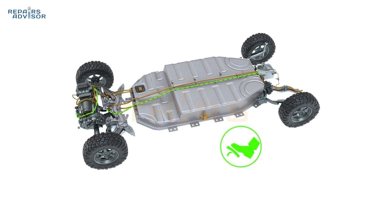
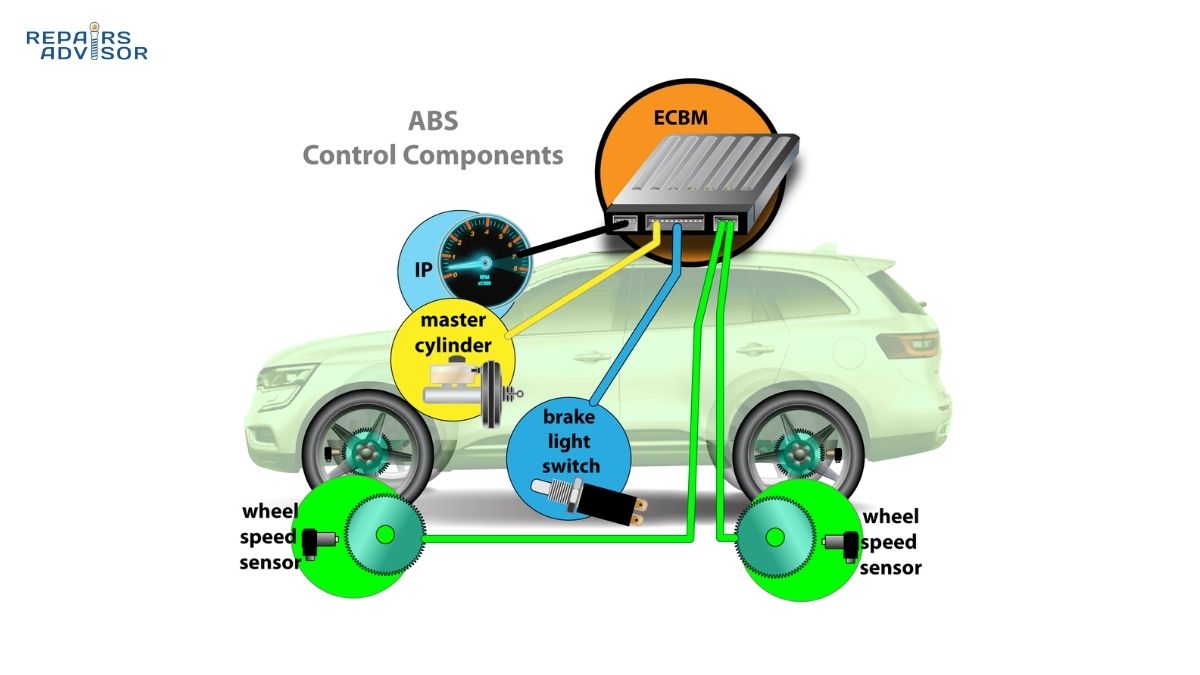
Anti-lock braking systems consist of four primary components working in perfect coordination: wheel speed sensors, an ABS control module, a hydraulic control unit (modulator), and a hydraulic pump. Each element plays a critical role in preventing wheel lockup while maintaining maximum braking force.
Wheel Speed Sensors: The System’s Eyes
Wheel speed sensors serve as the ABS system’s primary data source, continuously monitoring the rotational speed of each wheel and sending this information to the control module. Modern vehicles typically use one of two sensor technologies, each with distinct operating principles.
Passive magnetic sensors, found on older vehicles, generate their own voltage signal through electromagnetic induction. As the tone ring (also called a reluctor ring) rotates past the sensor, the changing magnetic field induces a voltage that fluctuates in frequency and amplitude proportional to wheel speed. These sensors are simple and reliable but less accurate than newer designs, particularly at low speeds.
Active Hall-effect sensors represent the modern standard and offer significantly improved accuracy. Unlike passive sensors, Hall-effect sensors receive a reference voltage from the ABS control module. As the tone ring’s teeth pass the sensor, they disrupt this reference voltage, creating a digital square-wave signal. This design provides accurate wheel speed data even at very low speeds—critical for systems like hill-start assist that operate when the vehicle is nearly stationary. The sensor signal frequency increases proportionally with wheel speed, allowing the control module to calculate precise rotational velocity.
Most modern vehicles employ four-sensor systems with one sensor at each wheel, typically mounted at the wheel hub or behind the brake rotor. This configuration provides the highest level of control precision, allowing the ABS system to modulate brake pressure independently at each wheel. The system typically activates at minimum speeds of 12-15 mph; below this threshold, wheel lockup isn’t a significant safety concern since vehicle momentum is minimal.
The tone ring itself—a toothed wheel that rotates with the hub—requires proper spacing from the sensor. This air gap, typically just a few millimeters, must remain consistent for accurate signal generation. Contamination by metal shavings, road debris, or corrosion can disrupt the signal and trigger ABS faults. For more technical details on wheel speed sensor operation and signal processing, see our guide on how wheel speed sensors work.
ABS Control Module: The System’s Brain
The ABS control module—sometimes called the electronic control unit (ECU) or electronic brake control module (EBCM)—functions as the system’s central processor, making thousands of calculations per second to determine optimal brake pressure at each wheel. This sophisticated computer continuously monitors rotational speed data from all four wheel speed sensors simultaneously, comparing each wheel’s speed to the others and to the vehicle’s overall speed.
When a wheel rotates significantly slower than the vehicle’s speed—indicating impending lockup—the control module instantly recognizes this as an impending lockup condition. The module’s algorithm accounts for multiple variables: current vehicle deceleration rate, individual wheel speeds, steering angle input, and even road surface conditions through analysis of wheel slip characteristics. Modern control modules can detect the subtle difference between a wheel that’s braking optimally (maximum traction) and one that’s about to lock up, initiating corrective action before the driver perceives any problem.
The control module commands the hydraulic valves in the modulator to adjust brake pressure, cycling up to 15 times per second during active ABS operation. This rapid modulation keeps each wheel operating at its optimal slip angle—typically 15-20% slip—where tire-to-road friction peaks. Too little slip means insufficient braking force; too much slip leads toward lockup and lost steering control.
Modern ABS control modules integrate extensively with other vehicle systems through Controller Area Network (CAN) bus communication. They share data with the engine control unit, transmission controller, stability control systems, and even navigation systems in some vehicles. This integration enables advanced features like predictive brake priming (slightly increasing brake pressure before an anticipated stop) and coordinated interventions between ABS, traction control, and stability control systems.
The control module also performs comprehensive self-diagnostic testing every time you start your vehicle. During the brief moment after ignition, you may hear clicking sounds as the system tests solenoid valves. This bulb-check function also illuminates the ABS warning light momentarily—completely normal operation. When the module detects any malfunction, it stores diagnostic trouble codes for technician retrieval, illuminates the ABS warning light, and typically disables anti-lock function while maintaining normal braking capability. This fail-safe design ensures you always have basic braking even if ABS fails.
Hydraulic Control Unit: Precision Pressure Management
The hydraulic control unit, or modulator, houses the solenoid-operated valves that actually control brake pressure at each wheel. This compact assembly contains multiple precision valves—typically three valves per wheel circuit in advanced systems—along with accumulators, check valves, and fluid passages. Understanding valve operation reveals how the system achieves such precise control.
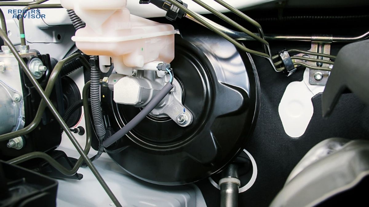
Each wheel circuit contains inlet and outlet valves controlled by the ABS module. The inlet valve connects the master cylinder to the brake caliper, while the outlet valve provides a path to release pressure back to the accumulator or pump. During normal braking when ABS isn’t active, inlet valves remain open and outlet valves stay closed, allowing brake pressure to flow directly from the master cylinder to the calipers. You’re in complete control through brake pedal force, exactly like a non-ABS vehicle. For more on how this hydraulic pressure is generated and controlled, see our comprehensive guide on how master cylinders work.
Modern hydraulic modulators represent remarkably sophisticated engineering. Early ABS systems distributed components throughout the vehicle—pump near the brake booster, hydraulic unit by the master cylinder, control module under the seat. Modern designs integrate everything into a single compact unit, typically mounted in the engine compartment near the master cylinder. This consolidation reduces weight, minimizes complex wiring harnesses, improves reliability, and simplifies service procedures.
When ABS activates, you’ll feel rapid pulsations through the brake pedal—the hydraulic equivalent of the system’s pressure cycling. This feedback, often described as grinding, buzzing, or the pedal “pushing back,” confirms the system is working correctly. Some drivers instinctively release pedal pressure when feeling this sensation, but doing so defeats the ABS system. Firm, continuous pedal pressure allows the system to operate at maximum effectiveness.
The valves within the modulator can become contaminated by metallic particles (copper from worn brake lines) and debris flowing in old brake fluid. This contamination can cause valves to stick, producing symptoms similar to master cylinder failure—soft pedal, inconsistent braking, or even loss of pressure. This underscores the importance of regular brake fluid service. Fresh brake fluid maintains hydraulic system integrity and prevents internal corrosion that can compromise ABS operation.
Hydraulic Pump: Rapid Pressure Restoration
The hydraulic pump works in tandem with the modulator to restore brake pressure after the outlet valves release it. When the control module commands pressure reduction at a wheel, the outlet valve opens and dumps fluid to a low-pressure accumulator or reservoir. The pump must then move this fluid back into the high-pressure system, maintaining brake pressure at the other wheels and enabling rapid reapplication of pressure to the wheel that momentarily lost it.
The pump consists of an electric motor driving a hydraulic pump mechanism—typically a piston pump or gear pump design. In modern integrated ABS units, the motor attaches directly to the bottom of the hydraulic modulator, creating a compact, self-contained assembly. The motor activates only during ABS events; if you hear the ABS pump running continuously with normal driving, this indicates a shorted ABS control module requiring professional diagnosis.
The pump must operate with extreme reliability because it’s critical for proper ABS cycling. During hard braking with ABS active, the pump runs continuously, rapidly moving brake fluid from the low-pressure side back to the high-pressure side. This creates the characteristic noise—a buzzing or grinding sound—that accompanies ABS activation. Combined with rapid solenoid valve cycling, this produces the pulsation you feel through the brake pedal.
Pump failures typically result from water ingress (particularly in vehicles driven through deep water or heavy rain) or internal component breakdown from age and use. Some pumps fail mechanically while others experience electrical failures in the motor windings. Professional diagnosis requires specialized equipment that can command the ABS system to activate individual solenoids and the pump, verifying proper operation. Many repair facilities now offer test-and-rebuild services for complete ABS assemblies, often providing better-than-original reliability through upgraded components.
How ABS Prevents Wheel Lockup: Step-by-Step Operation
Understanding ABS operation requires following the system through normal braking, lockup detection, intervention, and recovery. Each phase demonstrates the remarkable coordination between mechanical, hydraulic, and electronic systems.
Normal Braking Operation Without ABS Activation
During typical driving and gentle braking, the ABS system remains passive—monitoring conditions but not intervening. All four wheel speed sensors continuously transmit data to the control module at rates of 50-100 times per second. The control module compares these wheel speeds to each other and calculates vehicle speed based on their average. When wheel speeds remain relatively equal and deceleration rates appear normal, the control module takes no action.
The hydraulic system operates in its default configuration: inlet valves remain open, outlet valves stay closed. When you press the brake pedal, the brake booster multiplies your foot pressure, and the master cylinder converts this into hydraulic pressure. This pressure flows through the open inlet valves in the ABS modulator, through brake lines, and directly to the brake calipers at each wheel. The hydraulic pump remains inactive. You control braking force entirely through pedal pressure, exactly as you would in a vehicle without ABS.
The control module continuously monitors for conditions that indicate impending wheel lockup: wheel speed dropping significantly faster than vehicle speed, one wheel decelerating much faster than others, or wheel speed approaching zero while vehicle speed remains substantial. These conditions signal that tire traction is being exceeded and intervention is needed.
Detecting Impending Wheel Lockup
The control module’s lockup detection algorithm represents sophisticated signal processing. The module doesn’t wait for a wheel to completely lock up—by then, control would already be lost. Instead, it predicts lockup before it occurs by analyzing the rate of wheel deceleration.
Here’s the key insight: a wheel cannot decelerate infinitely fast. Physics limits how quickly a tire can slow down while maintaining grip on the road surface. If sensor data shows a wheel decelerating impossibly fast—much faster than vehicle physics allows—the control module knows that wheel is losing traction and approaching lockup. The threshold is typically set around 15-20% wheel slip, the point where tire friction approaches its maximum.
The control module also compares all four wheels to each other. On uniform surfaces, wheels should decelerate at similar rates during braking. If one wheel’s speed drops significantly faster than the others, it indicates that wheel is losing traction—perhaps due to a slippery spot, worn tire, or stuck brake caliper. The ABS system can address this by modulating pressure at just that wheel while maintaining full braking force at the other three wheels.
Environmental factors affect the detection threshold. On ice or snow, wheels may reach the lockup threshold at relatively modest braking force. On dry pavement, much higher brake pressure is required. The control module adapts its intervention threshold based on observed traction characteristics, essentially “learning” the road surface through wheel behavior during each brake application.
ABS Intervention Cycle: Three-Phase Pressure Modulation
When the control module detects impending lockup, it initiates the ABS intervention cycle—a three-phase process that repeats 5-15 times per second for as long as needed. This is where the system earns its name: anti-lock braking.
Pressure Hold Phase: The instant the control module detects a wheel approaching lockup, it commands the inlet valve for that wheel to close. This isolates that brake caliper from the master cylinder, preventing any additional pressure increase even if the driver pushes harder on the brake pedal. The outlet valve remains closed, so pressure is held constant at the caliper. The wheel continues to slow, but the locked brake pressure plateau gives it a moment to recover. The other three wheels, if they’re gripping properly, continue braking normally with full pressure.
Pressure Release Phase: If the wheel continues decelerating toward lockup despite held pressure, the control module moves to pressure release. The outlet valve opens, allowing brake fluid to escape from the caliper back to the accumulator. Pressure at that wheel drops rapidly—typically in just milliseconds. With reduced clamping force on the rotor, the wheel begins to accelerate and regain traction. This is the phase that creates the brake pedal pulsation drivers feel; as pressure releases, the pedal moves slightly inward. The sensation—rapid, firm pulsing—signals that ABS is working correctly, not that brakes are failing.
Pressure Reapplication Phase: As the wheel speed increases and grip returns, the control module sees the wheel accelerating back toward vehicle speed. The outlet valve closes and the inlet valve reopens, allowing pressure to rebuild. The hydraulic pump simultaneously works to restore system pressure, quickly reapplying braking force. Pressure increases until the wheel again approaches its traction limit, at which point the cycle repeats. Through this rapid cycling—5 to 15 complete cycles per second—the system maintains each wheel at its optimal slip angle where braking force is maximized while steering control is preserved.
During each cycle, the control module refines its understanding of available traction. If pressure can be increased substantially before the next lockup event, the system knows traction is good. If only slight pressure increases trigger lockup, the system recognizes reduced traction and modulates more gently. This adaptive behavior allows ABS to function effectively across wildly different surfaces, from dry pavement to ice.
The beauty of this system becomes apparent in emergency situations. While a human driver might pump the brakes 2-3 times per second at best, ABS modulates pressure 5-15 times per second with perfect consistency. The system never panics, never overcorrects, and maintains optimal brake force at each wheel independently. For more on how the physical brake components respond to this rapid pressure modulation, see our guide on how disc brakes work.
Multi-Wheel Coordination and System Configurations
Modern ABS systems come in several configurations, each with different levels of wheel control. The most advanced systems offer true four-channel control, while simpler systems use three-channel or even two-channel configurations.
Four-Channel, Four-Sensor ABS represents the current standard on passenger cars and represents the most sophisticated configuration. Each wheel has its own speed sensor and dedicated hydraulic valve channel. The control module can modulate brake pressure independently at all four wheels simultaneously. If the right front wheel hits a patch of ice while the other three wheels remain on dry pavement, four-channel ABS maintains full braking force at three wheels while modulating only the wheel that’s losing traction. This configuration provides maximum braking effectiveness and shortest stopping distances across all conditions.
Three-Channel, Four-Sensor ABS appears commonly on pickup trucks and older SUVs. The front wheels each have independent sensors and valve channels, allowing individual control. However, the rear axle shares a single valve channel, with one sensor monitoring both rear wheels or a single sensor on the rear differential. This means rear braking can only be modulated as a pair—both rear wheels receive the same brake pressure adjustment. While less sophisticated than four-channel systems, this configuration provides good performance at lower cost and works well for vehicles where weight distribution and load carry more variation.
Two-Channel, Four-Sensor ABS uses sensors at each wheel but controls the front wheels as a pair and rear wheels as a pair. This older configuration, rarely used on modern vehicles, provides basic ABS functionality at minimal cost but surrenders the precision of individual wheel control.
The sophistication of your ABS system affects its integration with other safety systems. Four-channel ABS enables advanced features like electronic stability control and individual wheel torque vectoring. Three-channel systems can still support traction control and basic stability assistance, though with less precision. Check your owner’s manual to understand your vehicle’s specific ABS configuration and capabilities.
ABS Performance Characteristics and Limitations
While ABS provides tremendous safety benefits in most conditions, understanding its performance characteristics across different surfaces helps you drive more safely and set appropriate expectations.
Surface-Specific Performance Analysis
Dry Pavement Performance: ABS delivers optimal performance on dry, paved surfaces. In these conditions, modern ABS systems typically reduce stopping distances compared to locked-wheel braking while maintaining full steering control. The system keeps tires operating at their peak friction coefficient—the sweet spot where maximum braking force meets sustained grip. NHTSA studies confirm that on dry roads, ABS provides measurably shorter stopping distances than non-ABS vehicles in emergency braking scenarios. Just as importantly, ABS allows drivers to steer around obstacles during emergency braking—a capability that has prevented countless collisions.
Wet Surface Advantages: Wet roads represent where ABS shows some of its most dramatic benefits. According to comprehensive NHTSA crash data analysis, ABS reduces fatal crashes by 24% and nonfatal crashes by 14% on wet roads. On wet pavement, wheels can lock up with relatively modest brake pressure, and locked wheels hydroplane easily—sliding across the water film rather than maintaining contact with the road surface. ABS prevents this lockup, keeping tires in contact with the pavement and maintaining both braking effectiveness and steering control. The system’s ability to prevent hydroplaning during emergency stops has saved countless lives in rainy conditions.
Snow and Ice Limitations: Here’s where ABS performance becomes more nuanced and sometimes counterintuitive. On snow-covered or icy roads, ABS may significantly increase stopping distances compared to locked wheels—yet it still provides important safety benefits. The reason relates to how tires interact with snow and ice. When wheels lock on loose snow or gravel, they can “dig in,” creating a buildup of material ahead of the tire that acts as a brake. ABS prevents this digging action by keeping wheels rotating. The result: longer stopping distances, but maintained steering control. NHTSA studies found ABS increased stopping distances on loose gravel by an average of 27.2% while still improving steering control and vehicle stability.
This represents an intentional design trade-off. ABS engineers prioritized steering control over absolute minimum stopping distance because maintaining vehicle control often matters more than stopping in the shortest distance. If an obstacle appears during braking, steering around it while continuing to slow is often a better outcome than locking up the wheels, sliding straight ahead with no steering control, and hitting the obstacle at slightly reduced speed.
Loose Gravel Considerations: Similar physics apply on loose gravel roads. Locked wheels can dig into gravel, creating significant braking force. ABS prevents this digging, resulting in potentially longer stopping distances but preserved steering ability. If you regularly drive on gravel roads, understanding this characteristic helps you adjust braking technique and following distances accordingly. Some vehicles offer the ability to disable stability control (which may also affect ABS operation) for off-road conditions where locked-wheel braking might be preferable.
The key takeaway: ABS is designed primarily for paved road emergency braking, where it excels. On low-traction surfaces, it still prevents complete loss of control, even if absolute stopping distance increases. Adapt your driving—increase following distance, reduce speed, and anticipate slippery conditions—rather than depending on ABS to overcome poor traction.
Integration with Advanced Safety Systems
ABS serves as the foundation for virtually every electronic safety system in modern vehicles. Understanding these connections reveals why ABS is so critical to overall vehicle safety.
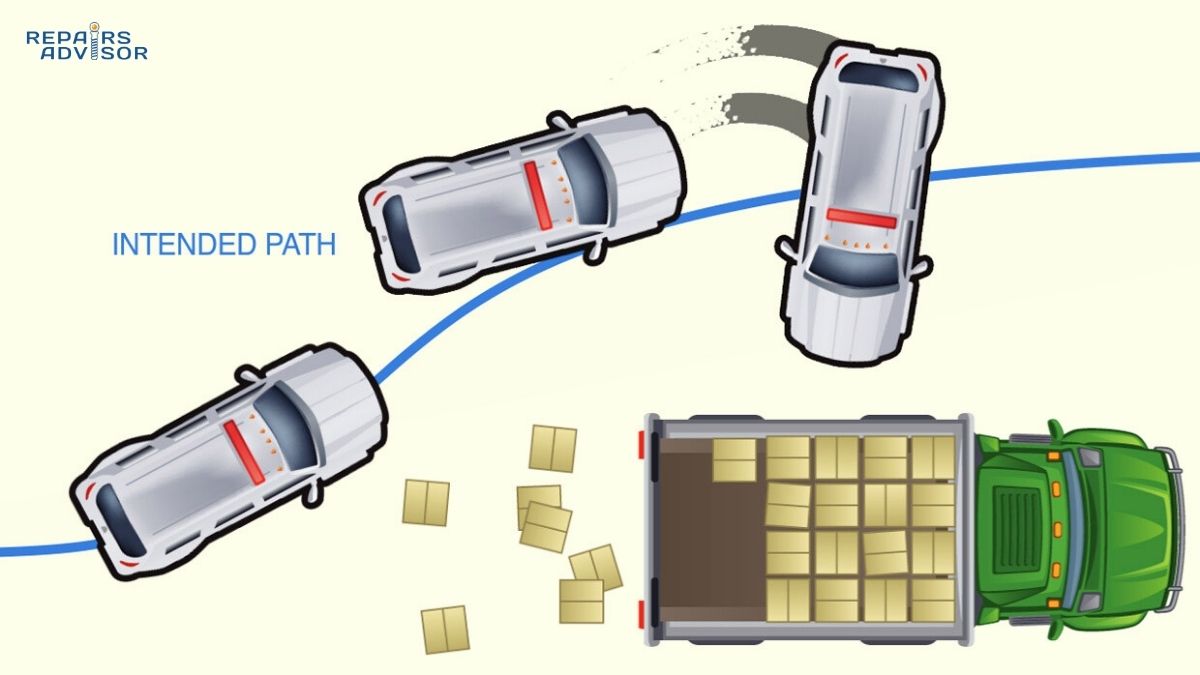
Electronic Stability Control (ESC) builds directly on ABS technology. Mandatory on all new passenger vehicles sold in the United States since 2012, ESC adds yaw rate sensors, lateral accelerometers, and steering angle sensors to the basic ABS hardware. When sensors detect that the vehicle is rotating (yawing) differently than the steering input commands—indicating a skid or loss of control—ESC uses the ABS hydraulic system to apply braking force to individual wheels. By braking the appropriate wheel(s), ESC creates a corrective moment that helps the vehicle track the driver’s intended path. This prevents both understeer (vehicle not turning as much as steering input commands) and oversteer (vehicle rotating more than steering input commands). Studies show ESC reduces fatal single-vehicle crashes by approximately 50%, making it one of the most effective safety technologies ever developed. Our detailed guide on how electronic stability control works explains the complete system operation.
Traction Control System (TCS) represents another direct ABS derivative. TCS uses the same wheel speed sensors but monitors for wheel spin during acceleration rather than wheel lockup during braking. When sensors detect a drive wheel spinning significantly faster than vehicle speed—indicating loss of traction—TCS applies the brake to that specific wheel and may also reduce engine torque. This intervention prevents wheel spin, maximizes acceleration traction, and improves vehicle stability during acceleration on slippery surfaces. The system relies entirely on ABS components: wheel speed sensors, the control module, and the hydraulic modulator. Learn more in our guide on how traction control systems work.
Automatic Emergency Braking (AEB) leverages the ABS hydraulic control unit to apply maximum braking force when forward-collision sensors detect an imminent crash. These systems use radar, cameras, or lidar to monitor the distance and closing speed with vehicles ahead. When a collision appears unavoidable and the driver hasn’t responded, AEB commands the ABS modulator to apply full braking force. The ABS system then prevents wheel lockup during this autonomous emergency braking, maintaining vehicle stability even during the maximum deceleration. As AEB becomes mandatory on more vehicles, the importance of properly functioning ABS grows—the system must be ready to prevent wheel lockup during autonomous braking events that may occur without driver input. See our comprehensive guide on how automatic emergency braking works for complete technical details.
This integration explains why ABS problems can affect multiple vehicle systems. A failed wheel speed sensor doesn’t just disable ABS—it also disables traction control, stability control, and any advanced driver assistance features that rely on wheel speed data. Maintaining your ABS system isn’t just about anti-lock braking; it’s about preserving the functionality of your vehicle’s entire safety ecosystem.
Common ABS Problems and Diagnostic Procedures
Like all vehicle systems, ABS components can fail or malfunction. Understanding common problems, their symptoms, and proper diagnostic procedures helps you identify issues early and seek appropriate professional service.
ABS Warning Light Activation and System Disable
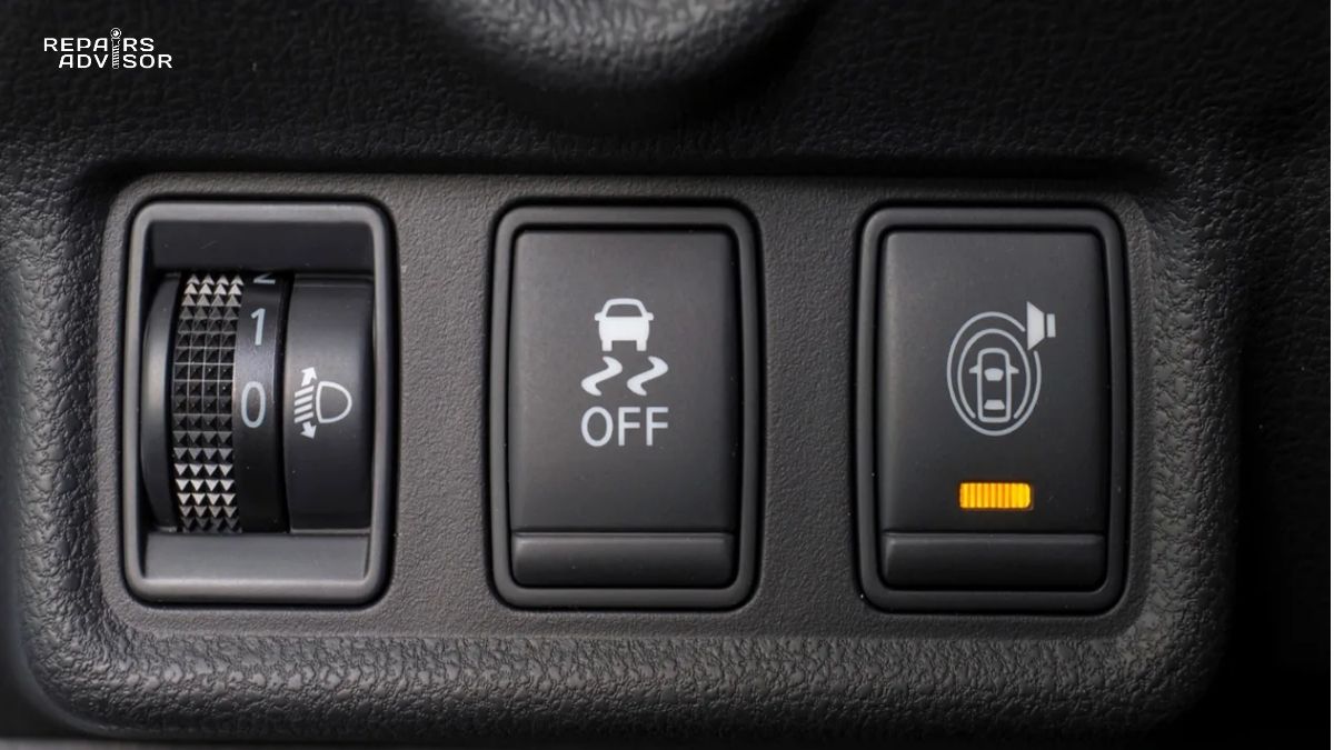
The ABS warning light—typically an amber light with “ABS” text or an icon—serves as your primary indicator of system problems. When this light illuminates and stays on, the ABS control module has detected a fault and disabled anti-lock braking function to prevent erratic system behavior. Your regular brakes continue functioning normally, but without the anti-lock capability.
Modern ABS systems perform comprehensive self-diagnostics every time you start the vehicle. During this brief test (typically 3-5 seconds), you’ll see the ABS light illuminate, hear some clicking from the hydraulic modulator as solenoid valves are tested, and then the light should extinguish. If the light remains on after this initial bulb check, a fault exists. If the light illuminates while driving, it indicates a problem has developed since the last self-test.
When the ABS light comes on, the control module stores diagnostic trouble codes (DTCs) that identify which sensor, circuit, or component triggered the fault. These codes provide invaluable diagnostic information for technicians. Common codes include wheel speed sensor circuit faults, hydraulic pump motor circuit problems, or control module internal faults. For example, Code C0031 specifically indicates a left front wheel speed sensor circuit malfunction—one of the most common ABS faults.
Important: While your basic brakes still work with the ABS light on, you’ve lost anti-lock capability—a significant safety system. Additionally, traction control and stability control (which depend on ABS components) will also typically be disabled. Have the system diagnosed as soon as practical. Don’t ignore an ABS warning light, as the problem won’t resolve itself and could indicate issues that may worsen over time.
Wheel Speed Sensor Failures: Most Common ABS Problem
Wheel speed sensor problems account for the majority of ABS faults. These sensors operate in harsh conditions—exposed to road spray, temperature extremes, vibration, and contamination—making them vulnerable to various failure modes.
Symptoms of Failed Wheel Speed Sensors:
- Illuminated ABS warning light (most common and often only symptom)
- Traction control and stability control lights also illuminated
- ABS system completely unresponsive during hard braking
- Incorrect ABS activation at low speeds or on smooth surfaces
- Speedometer failure in rare cases (on vehicles where vehicle speed is derived from wheel speed sensors)
Common Failure Causes: Many wheel speed sensors integrate into the wheel bearing hub assembly. When the bearing fails due to wear, the sensor typically fails simultaneously due to excessive vibration and movement. The sensor tip can also be damaged by road debris, or internal electronics can fail from age and thermal cycling. Very rusty reluctor rings (tone rings) can cause erratic signals even with a good sensor, as corrosion disrupts the uniform tooth pattern the sensor reads. Finally, wiring and connectors suffer from corrosion, particularly in salt-belt states where road salt accelerates deterioration.
Diagnostic Procedures: Professional diagnosis starts with retrieving diagnostic trouble codes using an OBD-II scanner. Codes typically identify which specific wheel has the faulty sensor. Visual inspection follows—checking the sensor, wiring, and connector for obvious damage, corrosion, or contamination. A multimeter resistance test verifies sensor winding integrity; most sensors should show 800-1,400 ohms resistance, though specifications vary by vehicle. An AC voltage test while manually rotating the wheel hub confirms signal generation; a functioning sensor should produce a small AC voltage (typically 0.1-0.5 volts) that increases in frequency with rotation speed.
Cleaning accumulated metal shavings or road debris from the sensor tip sometimes resolves intermittent faults, but failed sensors require replacement. Replacement costs typically range from $100-250 per sensor including labor at repair shops, or $40-80 for DIY replacement if you’re comfortable with basic hand tools. The most important aspect is addressing the problem promptly—ABS system failures shouldn’t be deferred. For detailed technical information on sensor operation and testing procedures, see our comprehensive guide on how wheel speed sensors work.
Hydraulic Control Unit and Pump Problems
Hydraulic control unit failures present more complex symptoms than simple sensor faults, often mimicking problems with other brake components like the master cylinder or brake calipers.
Symptoms of Hydraulic Control Unit Issues:
- Soft or spongy brake pedal feel
- Low brake pedal (pedal sinks toward floor)
- ABS activating inappropriately during normal braking
- Unusual noises from ABS modulator during normal (non-emergency) driving
- Visible brake fluid leaks around the ABS modulator
- ABS light illuminated with multiple fault codes stored
Common Causes: The most common cause of valve sticking involves contaminated brake fluid. Over time, moisture absorption in brake fluid promotes internal corrosion, generating metallic particles (particularly copper from brass components). These particles accumulate in the narrow valve passages within the hydraulic modulator, causing valves to stick in partially open or closed positions. A stuck outlet valve can result in a low brake pedal identical to master cylinder failure. Stuck inlet valves may prevent full brake application at specific wheels.
Water ingress into the ABS pump motor causes electrical failures, particularly in vehicles that frequently drive through deep water or have been flooded. Internal motor winding deterioration from age and heat cycling also occurs. If the ABS motor runs continuously with the vehicle idling (you’ll hear it), this indicates a shorted control module that’s constantly commanding pump operation—a clear sign of control module failure requiring professional diagnosis.
Professional Service Requirements: Hydraulic control unit diagnosis and repair requires specialized equipment. Many repair facilities now offer test-and-rebuild services for complete ABS assemblies. The module is tested on HIL (Hardware-In-the-Loop) test equipment that simulates vehicle operation, verifying valve operation, pump function, and control module logic under various conditions. Confirmed faults lead to rebuild with upgraded components—often higher-rated than original parts, potentially providing better-than-new reliability.
Rebuilding represents a cost-effective alternative to replacing complete ABS assemblies, which can cost $1,000-2,000 from dealers. Rebuilt units typically cost $300-700 with warranties, though prices vary by vehicle. The most important aspect: proper diagnosis distinguishes ABS hydraulic problems from issues with the master cylinder, brake calipers, or other brake components that can produce similar symptoms. A qualified technician with proper diagnostic equipment is essential for accurate diagnosis.
ABS Control Module and Electrical Faults
Control module problems can produce perplexing symptoms because the module manages all aspects of ABS operation. Failures may be complete (no ABS function) or intermittent (erratic operation).
Symptoms of Control Module Issues:
- ABS light illuminated with multiple, seemingly unrelated fault codes
- Erratic ABS behavior—activating when it shouldn’t or not activating when needed
- System failures during vehicle self-test on startup
- ABS pump running continuously
- Multiple wheel speed sensor codes stored simultaneously (suggesting a central processing problem rather than individual sensor faults)
Diagnostic Approaches: Proper diagnosis requires professional-grade scan tools that can monitor live ABS system data, command individual components for functional testing, and properly interpret complex fault codes. Technicians verify power and ground circuits to the control module, check for water damage or corrosion at module connectors, and may test CAN bus network communication. Some faults require module reprogramming with updated software from the manufacturer; others necessitate module replacement.
Control module problems sometimes relate to location and exposure. Modules mounted low in the vehicle or without adequate weather protection face water intrusion from driving through puddles, road spray, or water leaks. Checking for stored water inside the module housing provides important diagnostic information. If water intrusion has occurred, simply drying out and replacing the module may not resolve all issues—corrosion damage to connector terminals or circuit boards may require additional repair.
While control module replacement can be expensive ($300-1,000 for the module plus programming and labor), accurate diagnosis ensures you’re not replacing a good module when the actual problem lies elsewhere in the system.
Proper ABS Operation and Maintenance
Getting maximum safety benefit from ABS requires understanding how to use it correctly during emergencies and maintaining it properly throughout your vehicle’s life.
How to Use ABS Correctly During Emergency Braking
Proper ABS technique is remarkably simple, yet many drivers defeat the system through incorrect brake pedal technique learned from pre-ABS driving instruction.
The Critical Technique: During emergency braking, apply firm, continuous pressure to the brake pedal and hold it down. Do not pump the brakes. This is the single most important point about ABS operation and bears repeating: never pump the brake pedal in a vehicle equipped with ABS. Pumping the brakes—the technique taught to drivers before ABS—defeats the system by constantly resetting the ABS intervention cycle. The system needs sustained brake pressure to modulate effectively.
What to Expect During ABS Activation: When ABS engages, you’ll feel rapid pulsing through the brake pedal. This pulsation feels as though the pedal is pushing back against your foot, and it’s accompanied by grinding, buzzing, or groaning noises from under the hood. These sensations indicate the system is working correctly—not that your brakes are failing. The pedal pulsation comes from rapid pressure cycling at 5-15 times per second; the noise comes from solenoid valve operation and pump motor running. Continue firm, steady pedal pressure through these sensations.
Many drivers instinctively release pedal pressure when feeling ABS pulsation, believing something is wrong. Studies show approximately 44% of ABS-equipped vehicle drivers either release the brake pedal when feeling “a sense of crashing under feet” or pump the pedal the same way as conventional brakes. This incorrect operation prevents ABS from achieving maximum effectiveness, potentially increasing stopping distances and reducing accident avoidance capability.
Steering During ABS Braking: One of ABS’s greatest benefits—maintained steering control during maximum braking—only helps if you use it. During emergency braking with ABS active, you can steer around obstacles while continuing to brake hard. This capability has prevented countless accidents where locked wheels would have sent the vehicle straight ahead despite desperate steering inputs. Practice identifying escape paths during hard braking and remember that steering remains fully effective throughout the stop.
Driving Practices That Maximize ABS Effectiveness: ABS is supplemental safety technology, not a replacement for good driving practices. Maintain safe following distances that allow adequate reaction and stopping time. Reduce speed in poor weather conditions—ABS helps you maintain control during emergency stops, but can’t overcome physics on slippery surfaces. Stay alert and avoid distractions that delay your brake application. The sooner you begin braking in an emergency, the more time and distance the ABS system has to work with. ABS helps you brake more effectively, but it can’t compensate for inadequate following distance, excessive speed, or delayed reactions.
Routine Maintenance Requirements for ABS Longevity
Proper maintenance preserves ABS system functionality and prevents expensive repairs. While ABS systems are remarkably durable, several maintenance items directly affect their operation.
Brake Fluid Service: Brake fluid is hygroscopic—it absorbs moisture from the air over time. This moisture promotes internal corrosion in the ABS hydraulic modulator, master cylinder, and brake calipers. Moisture also lowers the fluid’s boiling point, risking vapor lock under hard braking. Most manufacturers recommend brake fluid replacement every 2-3 years regardless of mileage. This service flushes out contaminated fluid, removing moisture and suspended particles before they damage expensive ABS components. At $80-150 for a professional brake fluid flush, it’s inexpensive insurance against $1,000+ ABS hydraulic unit failures. For complete technical information on brake fluid properties and service requirements, see our guide on how brake fluid works.
Brake System Inspections: Regular brake inspections—typically during oil changes or at least annually—catch potential ABS problems early. Technicians should inspect wheel speed sensor wiring for damage, check sensor mounting and proper air gap, examine ABS modulator mounting and connections, and verify proper brake fluid level (low fluid can affect ABS operation). Many ABS problems announce themselves early through minor symptoms; catching them during routine inspection prevents roadside failures.
Wheel Speed Sensor Protection: When having brake work performed, ensure technicians don’t damage wheel speed sensors or their wiring. Sensor wires often route near brake components, making them vulnerable during brake pad or rotor replacement. Verify proper sensor reinstallation after wheel bearing replacement—incorrect air gap causes erratic signals. Clean accumulated metal shavings from magnetic sensors during brake service; these shavings can interfere with sensor operation even though the sensor itself remains functional.
Tire Maintenance: Proper tire maintenance directly affects ABS operation. Maintain correct tire pressure at all four wheels—underinflation or overinflation changes the tire’s rolling diameter, affecting wheel speed sensor readings. Use matching tires (same size and similar wear) on all four wheels; significant size mismatches confuse the ABS system. Replace worn tires before tread depth becomes critical; bald tires provide insufficient traction for effective ABS operation. Tire issues don’t cause ABS failures, but they prevent the system from delivering its full safety benefit.
When to Seek Professional Service
Certain symptoms demand immediate professional attention. Don’t delay when you notice:
Immediate Action Required:
- ABS warning light remains illuminated after engine start
- ABS warning light illuminates while driving
- Unusual brake pedal behavior—soft, spongy, or sinking toward floor
- Grinding or buzzing noises during normal (non-emergency) braking
- Complete loss of traction control or stability control function
- Brake fluid leaks anywhere in the brake system, particularly near the ABS modulator
- Front wheels locking up during normal braking
Safety Priority: Brake system problems represent serious safety concerns that should never be deferred. If wheels lock during braking, immediately stop driving and arrange for towing to a repair facility. While the vehicle may still have basic braking capability with the ABS light on, you’ve lost critical anti-lock protection. Modern vehicles integrate so many safety systems through the ABS that one failure can cascade into multiple safety system losses. Contact an experienced brake technician or ASE-certified mechanic as soon as you notice ABS-related symptoms.
Most ABS problems are relatively straightforward to diagnose with proper equipment and expertise. A failed wheel speed sensor might cost $100-250 to replace; a contaminated hydraulic modulator can be rebuilt for $300-700; even complete control module replacement typically runs $500-1,500 including programming. While not trivial expenses, these costs pale in comparison to accident-related expenses—or worse, accident-related injuries. The safety systems in your vehicle, with ABS as their foundation, represent some of the best investments in automotive safety technology ever developed.
Conclusion: ABS as the Foundation of Modern Vehicle Safety
Anti-lock Braking System technology represents one of the most significant safety advances in automotive history. By preventing wheel lockup through rapid brake pressure modulation—up to 15 times per second—ABS maintains vehicle steering control during emergency braking while providing maximum braking effectiveness across most road conditions. The four core components work in perfect coordination: wheel speed sensors continuously monitor wheel rotation, the control module analyzes this data and commands interventions, the hydraulic modulator precisely controls brake pressure at each wheel, and the hydraulic pump restores pressure for rapid cycling.
The proven safety statistics speak for themselves: 35% reduction in fatal accidents according to comprehensive NHTSA studies, 24% reduction in fatal crashes on wet roads, 22% reduction in motorcycle fatal crashes. Perhaps even more importantly, ABS serves as the foundation for virtually every electronic safety system in modern vehicles—electronic stability control, traction control, automatic emergency braking, and numerous advanced driver assistance systems all depend on ABS components and technology.
Safety Reminder: ABS enhances your control during emergency braking, but it doesn’t eliminate the need for safe driving practices. Maintain appropriate following distances, reduce speed in adverse conditions, stay alert and focused on driving, and remember that ABS is supplemental safety technology—not a substitute for good judgment. Use the system correctly: firm, continuous brake pedal pressure during emergencies, never pump the brakes, and maintain steering control throughout the stop.
Professional Consultation Recommendation: If you experience any brake system problems—unusual noises, pedal changes, warning lights, handling concerns, or system warning lights—have your vehicle inspected by a qualified technician immediately. Never drive a vehicle with compromised braking performance. While this guide provides comprehensive technical knowledge to help you understand your ABS system, diagnosis and repair should always be performed by trained professionals with appropriate diagnostic equipment. The brake system is too critical to your safety for DIY experimentation on components you’re not qualified to service.
ABS technology continues evolving with integration into autonomous driving systems, machine learning for surface detection, and coordination with vehicle-to-vehicle communication. The basic principle remains constant: maintaining wheel rotation during maximum braking preserves steering control and maximizes available traction. Whether you drive a 15-year-old sedan or a brand-new electric vehicle, your ABS system stands ready to help you maintain control during that one emergency stop that might save your life. Understanding how it works, using it correctly, and maintaining it properly ensures it will be there when you need it most.