Why Clutch Cables Are Critical for Manual Transmission Operation
Direct Answer: Clutch cables provide the mechanical connection between your clutch pedal and the clutch release mechanism, translating foot pressure into the force needed to disengage the clutch for smooth gear changes.
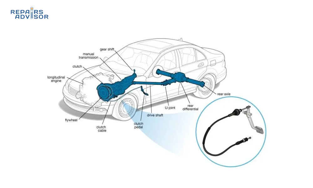
The clutch cable serves as the vital link in mechanical clutch actuation systems, directly controlling when power flows between your engine and transmission. When you press the clutch pedal, the cable transfers that input through a simple but effective mechanical system to the clutch release fork, allowing you to shift gears safely and smoothly.
Quick Facts:
- Function: Mechanical force transmission from pedal to clutch
- System Type: Cable-operated manual transmission control
- Maintenance Level: Periodic adjustment and lubrication required
- Failure Impact: Complete loss of clutch control, inability to shift gears
Understanding clutch cable mechanics helps you recognize early warning signs of wear and maintain proper clutch pedal feel throughout your vehicle’s life. This knowledge empowers you to make informed decisions about maintenance timing and avoid being stranded with a failed clutch system.
Safety Note: Clutch cable failure can leave you unable to disengage the clutch, creating dangerous situations where you cannot safely shift gears or stop the engine’s power transmission. Regular inspection and proper adjustment are essential for safe vehicle operation.
Clutch Cable Parts and Construction Explained
The clutch cable assembly consists of several precisely engineered components working together to provide reliable mechanical clutch actuation over thousands of operation cycles.
Primary Cable Assembly: The main component features a multi-strand steel wire cable housed within a flexible outer casing. The inner cable construction uses multiple steel strands for strength and flexibility, while the outer housing provides protection and proper routing throughout the engine compartment. High-quality cables incorporate moisture-resistant materials and corrosion protection.
Cable Housing and Protective Elements: The outer housing uses reinforced rubber or plastic construction with internal liner materials that reduce friction during cable movement. The housing incorporates rubber boots and grommets at both ends to prevent contamination while allowing smooth cable travel. Some designs include spiral-wound steel reinforcement within the housing for enhanced durability under high-load conditions.
End Fittings and Connection Hardware: Both ends feature specialized fittings designed for specific attachment points. The pedal end typically uses a clevis pin or ball-socket connection, while the release fork end employs various fitting types depending on transmission design. These fittings must withstand constant loading cycles while maintaining proper cable tension and alignment.
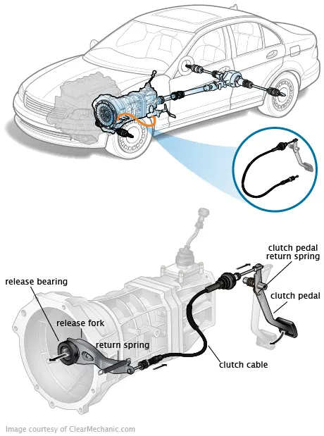
Adjustment Mechanisms: Most clutch cable systems incorporate adjustment points along the cable routing or at the release fork connection. These mechanisms allow for compensation of normal clutch wear and proper pedal height maintenance. Clutch release bearings work in conjunction with the cable system to complete the disengagement process.
Quality Variations: OEM cables typically offer superior corrosion resistance and precise fit, while performance options may include reduced-friction liners and enhanced flexibility. Budget alternatives often compromise on materials quality, leading to shorter service life and inconsistent pedal feel.
How Clutch Cable Works: Step-by-Step Operation
Understanding clutch cable operation reveals the elegant simplicity of mechanical clutch actuation and how proper cable condition directly affects driving experience and transmission longevity.
Step 1: Pedal Input and Initial Force Transfer When you depress the clutch pedal, the pedal lever multiplies your foot force through its mechanical advantage ratio. This amplified force pulls the inner cable through its housing, beginning the actuation sequence. The pedal linkage design determines the force multiplication factor, typically providing 8:1 to 12:1 mechanical advantage to reduce the effort required at your foot.
Step 2: Cable Force Transmission and Routing The tensioned cable transmits force along its entire length through the protective housing. Proper cable routing ensures smooth operation without binding or excessive friction. The cable follows specific paths designed by engineers to avoid heat sources, sharp edges, and moving components while maintaining the straightest possible route for optimal efficiency.
Step 3: Release Fork Actuation and Clutch Disengagement At the transmission end, cable tension pulls the release fork, which pivots to push the clutch release bearing against the pressure plate fingers. This action disengages the clutch disc from the flywheel, interrupting power flow to the transmission. The release fork geometry provides additional mechanical advantage, further reducing the pedal effort required.
Cable Tension and Proper Adjustment: Optimal cable operation requires proper free play adjustment – typically 1-2 inches of pedal travel before the cable begins pulling the release fork. This free play ensures complete clutch engagement when the pedal is released while preventing bearing wear from constant contact with pressure plate fingers.
Return Force and Pedal Feel: When you release the clutch pedal, the pressure plate springs provide return force through the entire cable system. This spring pressure pushes the release bearing away from the pressure plate, allowing the return spring to pull the cable back and return the pedal to its rest position. Proper cable condition ensures consistent pedal feel and positive return action.
Integration with manual transmission systems requires precise cable adjustment to ensure proper clutch engagement timing and prevent transmission damage from incomplete disengagement.
Clutch Cable Location and Access Guide
Locating and accessing clutch cable components requires understanding their routing path from the driver’s compartment through the firewall to the transmission bell housing area.
Primary Cable Routing and Identification The clutch cable typically runs from the clutch pedal assembly, through a firewall grommet, along the engine compartment’s left side (on most vehicles), and connects to the release fork at the transmission. You can identify the cable by following the pedal linkage connection – it’s usually a black or gray flexible cable approximately 8-10mm in diameter with protective housing.
Pedal End Access and Connection Points Inside the vehicle, locate the clutch cable connection at the upper end of the clutch pedal assembly. This connection point is typically visible by removing the lower dashboard panel or looking up behind the pedal cluster. The cable attachment uses either a threaded adjustment mechanism or a simple clevis pin connection, depending on your vehicle’s design.
Engine Compartment Routing and Inspection Points In the engine compartment, trace the cable from the firewall grommet toward the transmission. The cable usually follows a path avoiding heat sources like exhaust manifolds and sharp edges. Look for mounting clips that secure the cable to the chassis or engine block, preventing vibration damage and maintaining proper routing geometry.
Transmission End Access and Release Fork Connection The transmission end connection typically requires accessing the release fork from either above or below the vehicle, depending on engine configuration. On most front-wheel-drive vehicles, you’ll find the connection point by looking down at the transmission bell housing area. Rear-wheel-drive vehicles often require underneath access to reach the release fork connection.
Service Access Requirements and Safety Considerations Clutch cable service typically requires basic hand tools: wrenches for adjustment mechanisms, screwdrivers for cable routing clips, and possibly a flashlight for inspection in confined spaces. Always ensure the engine is cool before working around the cable routing to avoid contact with hot exhaust components.
Vehicle Variations and Cable Routing Differences Front-wheel-drive vehicles typically use shorter cables with more direct routing, while rear-wheel-drive applications require longer cables with additional mounting points. Manual gearbox configurations affect the specific release fork location and cable attachment method.
For troubleshooting cable-related issues, reference our comprehensive troubleshooting guide or explore vehicle-specific repair manuals through our automotive category for detailed procedures and specifications.
Safety Warning: Never attempt clutch cable service while the engine is running or immediately after operation when components may be extremely hot. Always use proper jack stands if underneath vehicle access is required, and ensure the vehicle cannot roll during service procedures.