The voltage regulator is the unsung hero of your vehicle’s electrical system, working silently behind the scenes to prevent catastrophic electrical damage. This critical component faces a challenging task: your alternator naturally produces increasing voltage as engine speed rises, potentially reaching 30-40 volts at highway speeds without regulation. At these voltage levels, every electrical component in your vehicle—from headlight bulbs to expensive computer modules—would fail within minutes. The voltage regulator solves this problem by maintaining a stable 13.5-14.8 volt output regardless of whether you’re idling at a stoplight or cruising at 70 mph.
Understanding how voltage regulators work reveals the sophisticated electronic control that protects your vehicle’s electrical system while ensuring optimal battery charging. Modern voltage regulators continuously monitor battery voltage and adjust alternator output hundreds to thousands of times per second, responding to changing electrical loads and operating conditions with remarkable precision. This constant regulation balances two critical functions: maintaining sufficient voltage to power all vehicle systems and charge the battery, while preventing dangerous overcharging that can cause battery explosions or burn out sensitive electronics.
When voltage regulators fail, the consequences range from inconvenient to dangerous. Symptoms include flickering lights, rapidly dying batteries, or the catastrophic scenario of overcharging that creates hydrogen gas and risks battery explosion. This guide explains the critical role of voltage regulation, the electronic components that make it work, the complete regulation process, and how to recognize failure symptoms before they leave you stranded or cause expensive damage.
Safety Note: Voltage regulator testing involves working with live electrical current and potentially explosive battery conditions. While basic multimeter testing is accessible to intermediate DIY enthusiasts, modern smart charging systems require professional diagnostic equipment. If you detect voltage readings above 15 volts while your engine is running, stop driving immediately and seek professional service—this overcharging condition is an emergency that can cause battery explosion.
Why Voltage Regulation Is Critical for Electrical Function
The fundamental problem voltage regulators solve stems from how alternators generate electrical power. As your alternator spins faster with increasing engine speed, it naturally produces higher voltage—a physical consequence of electromagnetic induction. Without regulation, an alternator might produce 12-14 volts at idle, 20 volts at city driving speeds, and 35-40 volts or more at highway speeds. This voltage variability would be catastrophic for modern vehicles packed with sensitive electronic components designed to operate within a narrow voltage range.
Overvoltage causes immediate and progressive damage throughout the electrical system. Headlight and interior light bulbs burn out prematurely as excessive voltage overheats their filaments. Electronic control modules, which manage everything from fuel injection to transmission shifting, suffer component failure when exposed to voltage spikes beyond their 16-volt maximum rating. Most critically, excessive charging voltage causes batteries to overheat, boil off electrolyte, and generate dangerous hydrogen gas that can explode with devastating results. Even moderately high voltage—say, 16-18 volts—accelerates battery failure and shortens the lifespan of every electrical component in the vehicle.
Conversely, insufficient voltage creates equally problematic conditions. When the voltage regulator fails to maintain adequate charging voltage, the battery slowly depletes as it supplies power to vehicle systems without receiving sufficient recharge. You’ll first notice dimming headlights at idle and sluggish power window operation. As the battery continues to discharge, the starter motor struggles to crank the engine. Eventually, voltage drops below the minimum required for fuel injection and ignition systems, and the engine stalls—leaving you stranded regardless of how much fuel remains in your tank.
Voltage regulators solve these problems by maintaining constant output within the optimal 13.5-14.8 volt range across all operating conditions. This precision requires rapid response capabilities, as voltage regulators adjust alternator field current hundreds to thousands of times per second. When you activate your headlights or air conditioning, electrical demand increases and battery voltage drops slightly—the regulator detects this drop within milliseconds and increases alternator output to compensate. When you turn accessories off, the regulator immediately reduces output to prevent overcharging. This continuous adjustment happens so smoothly that you never notice the complex electronic control protecting your vehicle’s electrical health.
Modern smart charging systems take voltage regulation far beyond simple voltage maintenance. These advanced systems communicate with the vehicle’s computer network through CAN bus connections, coordinating with engine management systems to optimize both electrical performance and fuel economy. After a cold start, the system may command higher charging voltage—14.5-14.8 volts—to quickly replenish the battery after cranking. During steady highway cruising, voltage may be reduced to 13.8-14.0 volts, decreasing the mechanical load on the engine and improving fuel economy by 2-3%. Some systems even monitor battery state of charge and adjust charging profiles to extend battery life, providing higher voltage for partially discharged batteries and reducing output when batteries are fully charged.
Temperature compensation represents another critical voltage regulation feature that adapts charging voltage to environmental conditions. Cold batteries require higher charging voltage to overcome increased internal resistance, while hot batteries need lower voltage to prevent overcharging and electrolyte loss. Advanced regulators incorporate temperature sensors that adjust the target voltage based on battery or ambient temperature—raising it to 14.6-14.8 volts in freezing conditions and lowering it to 13.8-14.2 volts in extreme heat. This temperature-compensated regulation dramatically improves battery charging efficiency and longevity across varying climates.
The safety implications of proper voltage regulation extend beyond component protection. Failed voltage regulators that allow overcharging create genuine fire and explosion hazards. Overcharged batteries generate hydrogen gas—the same fuel that powers rockets—which accumulates in the battery case and engine compartment. A single spark from any source can ignite this gas, causing violent battery explosions that spray sulfuric acid and plastic shrapnel. This isn’t a theoretical risk: improperly regulated charging systems cause hundreds of battery explosions annually, resulting in serious injuries including acid burns and eye damage. Conversely, undercharging failures leave drivers stranded in potentially dangerous situations when their vehicles die unexpectedly.
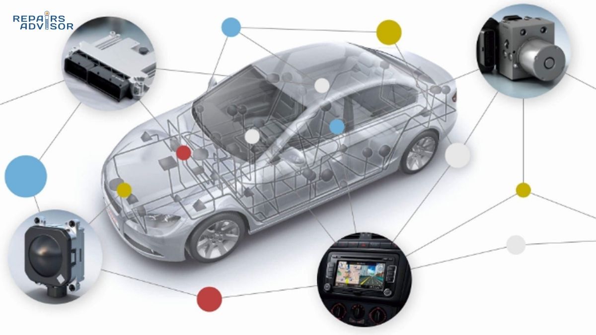
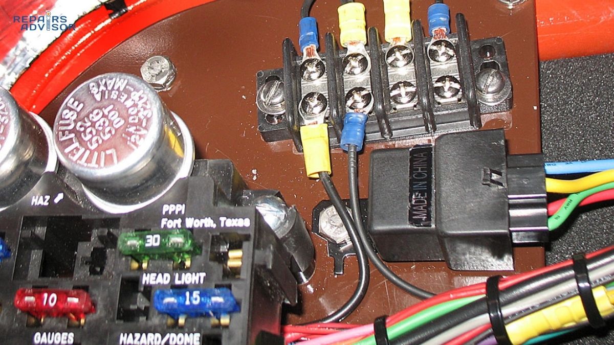
Professional technicians understand that voltage regulation integrates with broader vehicle systems in ways that affect overall performance and reliability. The charging system must coordinate with automotive relays and fuses that protect electrical circuits, work within the capacity of the electrical wiring infrastructure, and respond to signals from various vehicle computers. In modern vehicles, the voltage regulator isn’t an isolated component—it’s an integral part of a sophisticated power management network that balances electrical generation, distribution, storage, and consumption across dozens of systems operating simultaneously.
Voltage Regulator Parts and Electronic Control Explained
Voltage regulators employ sophisticated electronic circuits housed in compact, heat-resistant packages integrated into or mounted near the alternator. Understanding the key components reveals how these devices achieve precise voltage control through rapid electronic switching rather than mechanical adjustment. Modern solid-state regulators replaced earlier mechanical designs that used electromagnetic coils and contact points, providing dramatically improved reliability, faster response times, and maintenance-free operation.
The sensing circuit forms the foundation of voltage regulation, continuously monitoring battery voltage with precision. This circuit typically employs a voltage divider—resistors arranged to create a proportional sample of battery voltage—connected to a comparator circuit that measures the actual voltage against an internal reference. The reference voltage, usually a precision Zener diode or integrated circuit, provides an unwavering comparison point representing the target charging voltage (typically 14.0-14.4 volts at moderate temperatures). The comparator detects even minute deviations between actual battery voltage and the reference, measuring differences as small as 0.1 volts with response times measured in microseconds. This continuous monitoring provides the feedback necessary for precise voltage control across varying loads and operating conditions.
The control module translates voltage sensing into alternator field current adjustment through high-speed electronic switching. Power transistors or MOSFETs (Metal-Oxide-Semiconductor Field-Effect Transistors) control the current flowing to the alternator’s field coil, which creates the electromagnetic field that determines alternator output. These switching devices operate using pulse-width modulation (PWM), turning field current on and off hundreds to thousands of times per second. The duty cycle—the percentage of time the switch is closed versus open—determines the average field current. A 70% duty cycle means the field receives current 70% of the time and is disconnected 30% of the time, while a 30% duty cycle reverses this ratio. By varying duty cycle from 0% (alternator off) to 100% (maximum output), the regulator achieves infinitely variable control over alternator output despite using simple on-off switching.
Field current control directly determines alternator output because the strength of the electromagnetic field in the rotor determines how much voltage is induced in the stator windings. When the regulator increases field current by raising PWM duty cycle, the rotor’s magnetic field strengthens, inducing higher voltage in the stator and increasing alternator output. When battery voltage rises above the setpoint—perhaps because electrical loads decreased when you turned off the headlights—the regulator reduces field current, weakening the magnetic field and decreasing output until voltage returns to the target range. This relationship between field current and output voltage allows the regulator to control a 100+ amp alternator using only 3-7 amps of field current, making electronic regulation both efficient and practical.
Temperature compensation circuits represent a critical refinement that adapts charging voltage to environmental conditions. These circuits incorporate thermistors (temperature-sensitive resistors) or integrated temperature sensors that monitor either battery temperature or ambient air temperature near the alternator. As temperature changes, the compensation circuit adjusts the reference voltage used by the comparator, effectively changing the target charging voltage. In cold conditions below 50°F, the circuit raises target voltage to 14.4-14.8 volts to overcome increased battery internal resistance and ensure adequate charging. In hot conditions above 100°F, it lowers target voltage to 13.8-14.2 volts to prevent overcharging and excessive water loss from the battery electrolyte. This temperature compensation can extend battery life by 30-50% by maintaining optimal charging voltage across seasonal temperature variations.
Modern voltage regulators come in two primary configurations that differ in location and integration with the alternator assembly. Internal regulators, standard on virtually all vehicles manufactured since the 1990s, mount inside the alternator housing as either a separate replaceable module or integrated into the alternator’s rear end assembly. These compact solid-state units benefit from the alternator’s cooling airflow and eliminate external wiring that could corrode or fail. Internal regulators typically feature terminals for battery sense, ignition switch input, and field coil connection, with some designs incorporating diagnostic outputs that communicate with the vehicle’s computer network. When internal regulators fail, replacement usually requires either removing the alternator and replacing the regulator module (1-2 hour job requiring partial alternator disassembly) or replacing the entire alternator assembly.
External regulators, common in vehicles manufactured before 1990 and still used in some heavy-duty applications, mount separately from the alternator on the firewall, inner fender, or radiator support. These larger units connect to the alternator through wiring harnesses that carry field current and battery sense signals. External regulators offer easier replacement without alternator removal and sometimes allow for adjustment of voltage setpoints—though improper adjustment can cause charging problems or damage. Classic mechanical external regulators used electromagnetic coils and vibrating contact points to control field current, while later solid-state external designs employed transistor switching similar to modern internal units. External regulator replacement is relatively straightforward: disconnect the wiring connector, remove two mounting bolts, and install the replacement—a 15-30 minute job accessible to DIY mechanics.
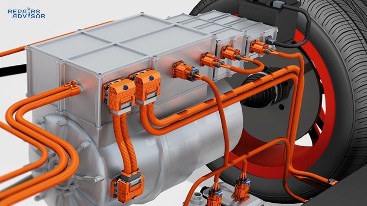
Hybrid and electric vehicles employ variations on traditional voltage regulation to manage their dual-voltage electrical systems. These vehicles maintain a conventional 12-volt system for accessories and vehicle electronics alongside high-voltage battery systems (200-400+ volts) for propulsion. A DC-DC converter replaces or supplements the traditional alternator, stepping down high-voltage battery power to charge the 12-volt battery and power conventional electrical systems. The voltage regulation in these converters follows similar principles—sensing 12-volt system voltage and modulating converter output to maintain proper charging—but uses more sophisticated control algorithms that coordinate with the high-voltage battery management system and regenerative braking. Professional service is mandatory for these systems due to high-voltage electrical hazards that can cause fatal electric shock.
Power handling and thermal management represent critical design challenges for voltage regulators despite their small size. The field current they control—typically 3-7 amps at 12 volts—represents 36-84 watts of power that must pass through the regulator’s switching transistors. Additionally, the switching action itself generates heat through electrical resistance during the brief moments when transistors transition between on and off states. Regulators dissipate this heat through aluminum housings that act as heat sinks, often with cooling fins to increase surface area. The alternator’s internal cooling fan pulls air through the housing, carrying heat away from the regulator components. At high ambient temperatures or during sustained high-output operation, some regulators incorporate thermal protection that reduces alternator output to prevent regulator failure—a safety feature that may result in temporarily reduced charging capacity during extreme conditions.
How Voltage Regulation Works: Complete Process
The voltage regulation process operates as a continuous feedback loop that monitors electrical system conditions and adjusts alternator output with remarkable speed and precision. Understanding each step reveals the sophisticated control that maintains stable voltage despite constantly changing engine speeds, electrical loads, and operating conditions. This process occurs automatically and continuously while the engine runs, requiring no driver intervention while preventing the electrical chaos that would result from unregulated alternator output.
Voltage sensing and monitoring begins the regulation cycle by providing accurate, real-time information about battery and electrical system voltage. The regulator’s sensing circuit connects directly to battery positive and negative terminals (or to the alternator’s output terminal, which reflects battery voltage during operation). The voltage divider circuit—typically two precision resistors in series—creates a scaled-down voltage proportional to battery voltage, bringing the 12-14 volt system voltage into the range suitable for the comparator circuit’s sensitive electronics. This scaled voltage reaches the comparator input dozens to thousands of times per second depending on regulator design, providing essentially continuous monitoring. Modern regulators sample voltage so frequently that they detect even momentary voltage fluctuations caused by sudden electrical load changes like electric fuel pump activation or radiator fan startup.
The sensing accuracy determines regulation precision, with high-quality regulators maintaining voltage within ±0.2 volts of the setpoint across all operating conditions. Multiple sampling points in some advanced designs ensure accuracy: the regulator might monitor voltage at both the alternator output terminal and the battery terminal, detecting voltage drop through the charging system wiring and compensating accordingly. This dual-sensing prevents the common problem where poor ground connections or corroded cables cause voltage drop between the alternator and battery—without dual sensing, the regulator would see proper voltage at the alternator while the battery receives insufficient charging voltage due to wiring resistance.
Error detection and decision making constitute the regulator’s “brain,” analyzing voltage measurements and determining the required response to maintain optimal charging voltage. The comparator circuit subtracts the scaled actual voltage from the reference voltage, producing an error signal that represents the deviation from target voltage. A negative error signal indicates battery voltage exceeds the setpoint—the regulator must reduce alternator output to prevent overcharging. A positive error signal indicates battery voltage falls below the setpoint—the regulator must increase output to restore proper charging. The magnitude of the error signal determines the urgency and magnitude of the correction: a small deviation might trigger a minor 5-10% adjustment in field current, while a large deviation demands a 30-50% correction.
The control algorithm that processes error signals incorporates sophistication beyond simple proportional response. Basic regulators use proportional control, adjusting field current in direct proportion to the voltage error. Advanced regulators employ proportional-integral-derivative (PID) control algorithms that respond to not only the current error but also accumulated error over time (integral control) and the rate of change of error (derivative control). This sophisticated control prevents oscillation where voltage overshoots the target and bounces above and below the setpoint, instead achieving smooth regulation with minimal fluctuation. The control algorithm also implements safety priorities: when voltage exceeds safe limits, the regulator immediately cuts field current completely regardless of other considerations, protecting the electrical system from damage even if this temporarily sacrifices optimal charging.
Field current modulation translates the control decision into physical action through high-speed switching of the field coil circuit. Power transistors or MOSFETs in the regulator act as electronic switches that connect and disconnect the field coil to battery voltage at frequencies typically ranging from 100 to 2,000 times per second. When the error signal indicates a need for increased output, the regulator increases PWM duty cycle—the field receives current for a greater percentage of each switching cycle. For example, increasing duty cycle from 50% to 70% means the field coil is energized 70% of the time instead of 50%, increasing the average field current by 40% and strengthening the rotor’s electromagnetic field proportionally.
This switching action occurs so rapidly that the field coil cannot fully de-energize during the brief off periods—the magnetic field weakens slightly but persists due to the coil’s inductance. The result is a relatively smooth average field current that varies with duty cycle changes, despite the on-off nature of the switching. The regulator can modulate field current from zero (0% duty cycle, alternator producing no output) to maximum (100% duty cycle, alternator at full output capacity) with infinite variability between these extremes. This precise control allows the regulator to match alternator output exactly to electrical system needs across the full range of operating conditions.
Alternator output response to field current changes demonstrates the electromagnetic principles underlying alternator operation. As field current increases and strengthens the rotor’s magnetic field, the rotating field induces higher voltage in the stationary stator windings through electromagnetic induction—the same principle that allows electric generators to convert mechanical motion into electrical energy. The alternator’s rectifier bridge converts this three-phase AC voltage into DC output that flows to the battery and electrical system. Stronger field current produces proportionally higher stator voltage and increased alternator output current capacity. The regulator can thus control a 120-amp alternator’s output from zero to maximum using only 3-7 amps of field current—a roughly 20:1 amplification that makes electronic regulation practical and efficient.
The response time from field current change to alternator output change typically spans 0.1 to 0.5 seconds, limited by the mechanical inertia of the spinning rotor and the electrical inductance of the alternator windings. This slight lag explains why you might briefly see headlights dim when starting the air conditioning compressor—the sudden electrical load drops system voltage, the regulator increases field current within milliseconds, but alternator output takes a fraction of a second to respond, during which lights may dim briefly before voltage recovers. Modern regulators anticipate these predictable load changes through integration with vehicle computer systems, pre-emptively increasing alternator output just before heavy loads activate.
Load response and dynamic adjustment showcase the regulator’s ability to maintain stable voltage despite constantly changing electrical demands. When you activate headlights, the sudden 10-15 amp load increase draws power from the battery initially, causing voltage to drop by 0.2-0.5 volts. The regulator’s sensing circuit detects this drop within microseconds, the error detection determines the required field current increase, and the control module raises PWM duty cycle to strengthen the alternator’s output. Within a fraction of a second, alternator output increases to match the new load, voltage returns to the setpoint, and the battery begins recharging from its brief discharge. This entire sequence happens so quickly and smoothly that you perceive only stable electrical system operation despite the complex adjustments occurring in the background.
Load decreases trigger the opposite response with equal precision. When you turn off the headlights, electrical demand drops suddenly and alternator output momentarily exceeds the reduced load, causing voltage to rise 0.2-0.5 volts above the setpoint. The regulator detects this voltage increase, reduces field current by lowering PWM duty cycle, and alternator output decreases to match the lower electrical demand. The battery transitions from charging to a float state where it receives only enough current to maintain full charge without overcharging. The regulator maintains this delicate balance continuously, adjusting alternator output dozens of times per minute as various electrical loads cycle on and off during normal vehicle operation.
Temperature compensation and adaptive control refine basic voltage regulation to account for environmental conditions and operating state that affect optimal charging voltage. The temperature compensation circuit monitors battery or ambient temperature through thermistor or integrated temperature sensor inputs, adjusting the reference voltage used by the comparator based on temperature measurements. In freezing conditions around 0°F, the circuit may raise target voltage to 14.7-14.8 volts to overcome the dramatically increased internal resistance of cold batteries and ensure adequate charging. At moderate temperatures around 70°F, target voltage settles at the standard 14.0-14.4 volt range. In extreme heat above 110°F, target voltage drops to 13.8-14.2 volts to prevent excessive gassing and water loss from hot batteries.
Integration with modern vehicle systems elevates voltage regulation from standalone component function to coordinated power management across the entire vehicle electrical architecture. Smart charging systems communicate with the engine control module through vehicle network connections, receiving and transmitting information about engine operating conditions, battery state of charge, electrical load predictions, and fuel economy optimization strategies. After cold starts, the system commands higher charging voltage for 10-30 minutes to quickly replenish the battery’s charge depleted by cranking. During steady-state highway cruising, the system may reduce charging voltage to 13.8-14.0 volts and enter a “fuel economy mode” that minimizes alternator load on the engine, reducing parasitic drag and improving fuel economy by an estimated 2-3%.
Some advanced systems employ predictive load management that pre-emptively adjusts alternator output before load changes occur. When the vehicle’s computer detects that you’ve pressed the brake pedal, it knows the brake lights will activate in milliseconds and pre-emptively increases alternator output to accommodate this load. Similarly, the system tracks patterns of electrical component usage and predicts upcoming loads—if you typically activate windshield wipers after turning on headlights, the system learns this pattern and prepares accordingly. Stop-start systems that shut down the engine at traffic lights require special voltage regulation strategies: during the stopped phase, the alternator provides no output and the battery must power all electrical loads; upon restart, the regulator commands maximum alternator output to rapidly recharge the battery before the next stop cycle. These sophisticated control strategies require professional diagnostic tools to properly test and troubleshoot, as simple voltage measurements cannot reveal the complex communications and coordinated control occurring across multiple vehicle computer modules.
Failure Symptoms, Testing, and When to Consult Professionals
Voltage regulator failures manifest through distinct symptoms that range from minor inconveniences to dangerous emergency conditions requiring immediate action. Recognizing these symptoms early allows you to address charging system problems before they cause expensive secondary damage or leave you stranded in potentially hazardous situations. The three primary failure modes—overcharging, undercharging, and erratic regulation—each produce characteristic symptoms that provide diagnostic clues to experienced technicians and observant vehicle owners.
Overcharging symptoms represent the most dangerous failure mode and demand immediate attention to prevent battery explosion or electrical fire. When the voltage regulator fails and allows uncontrolled alternator output, voltage can rise to 16-20 volts or higher during normal driving. You’ll first notice bulbs burning out with unusual frequency—headlights, interior lights, and dashboard bulbs may last only weeks instead of years when subjected to excessive voltage. The battery becomes hot to the touch even during short drives, and you may smell a distinctive sulfur odor (resembling rotten eggs) caused by the electrolyte boiling and releasing hydrogen sulfide gas. In severe cases, the battery case may bulge or distort from internal pressure as water boils out of the electrolyte and gases accumulate.
If you suspect overcharging, use a digital multimeter to check battery voltage immediately—with the engine running at 1,500-2,000 RPM, voltage above 15.0 volts indicates overcharging that requires immediate action. Do not continue driving. Overcharging creates explosive mixtures of hydrogen and oxygen gas both inside the battery and in the engine compartment. A single spark from any source—a loose battery cable, a tool dropped across terminals, even static electricity—can ignite these gases and cause violent battery explosion that sprays sulfuric acid and molten plastic. Turn off the engine, remove the keys, and arrange for towing to a repair facility. The small cost of a tow service pales compared to the medical expenses from acid burns or the replacement cost of an engine compartment destroyed by fire.
Professional technicians also watch for secondary indicators of chronic overcharging that may not trigger immediate emergency response but indicate regulation problems requiring correction. Corroded battery terminals and cables that require frequent cleaning suggest long-term overcharging that causes excessive gassing and acid mist emission. Electrical accessories that fail prematurely—power window motors, blower motors, wiper motors—may indicate voltage stress from inadequate regulation. Dashboard warning lights for ABS, airbag, or other systems might indicate computer module damage from voltage spikes. These symptoms warrant comprehensive charging system testing to identify and correct regulator problems before they progress to catastrophic failure.
Undercharging symptoms develop more gradually but ultimately leave you stranded when the battery depletes beyond the point of starting the engine. The earliest indicator is difficulty starting after the vehicle sits overnight or for extended periods—the battery lacks sufficient charge to crank the engine vigorously, resulting in slow cranking or multiple attempts required to start. As undercharging continues, you’ll notice dimming headlights particularly noticeable at idle, slow power window operation that improves when you rev the engine, and reduced performance of electrical accessories like the radio or climate control system.
The battery warning light on the dashboard—typically a red battery symbol or the word “CHARGE”—illuminates when the vehicle’s computer detects charging voltage below approximately 13.0 volts with the engine running. Some vehicles use a “Check Charging System” message or similar text warning. Never ignore these warnings: they indicate your vehicle is running on battery power alone, depleting the battery with every minute of operation. Depending on electrical load and battery condition, an undercharging vehicle may run for 20 minutes to 2 hours before the battery depletes sufficiently to stall the engine. The starter motor requires tremendous current—150-300 amps—so once the battery depletes to the point where it can no longer crank the engine, you’re stranded until the battery can be recharged or jumped.
Testing charging voltage with a digital multimeter provides definitive diagnosis of undercharging conditions. With the engine running at idle, measure voltage across the battery terminals—properly functioning systems should show 13.5-14.8 volts. Readings below 13.0 volts indicate undercharging from voltage regulator failure, alternator failure, or serious wiring problems in the charging circuit. Rev the engine to 2,000 RPM and observe whether voltage increases—if it remains below 13.0 volts, the alternator or regulator has failed. If voltage rises but only to 13.0-13.5 volts, the regulator may be marginally functional but set too low, or the alternator may be weak and incapable of producing full output.
Erratic regulation produces the most confusing symptoms because voltage and charging performance fluctuate unpredictably rather than remaining consistently too high or too low. You might notice headlights and dashboard lights that brighten and dim randomly as you drive, changing intensity without correlation to engine speed or electrical load changes. The battery warning light may flicker intermittently or illuminate only under certain conditions like highway driving or when multiple accessories are operating. Voltage measurements with a multimeter show unstable readings that bounce between 12-16 volts, sometimes swinging across this range in seconds.
These erratic symptoms suggest failing regulator components that function intermittently, corroded or loose electrical connections in the charging system, or alternator problems like worn brushes or failing diodes that produce variable output. Diagnosis requires careful inspection of all charging system connections, measurement of voltage at multiple points in the charging circuit, and possibly oscilloscope testing to observe the alternator’s output waveform and identify rectifier problems. This level of diagnosis exceeds the capabilities of basic multimeter testing and benefits from professional expertise and specialized test equipment.
Basic voltage testing with a multimeter provides valuable diagnostic information accessible to intermediate DIY mechanics willing to work carefully with electrical systems. You’ll need a quality digital multimeter capable of measuring DC voltage in the 0-20 volt range—automotive-specific models are available for $30-100, though any decent multimeter works fine. Safety first: Wear safety glasses to protect against battery acid spray if a terminal sparks, and work in a well-ventilated area away from ignition sources since batteries emit explosive hydrogen gas. Never wear metal jewelry or watches that could contact battery terminals and create dangerous short circuits.
The testing procedure progresses through several measurements that reveal both battery condition and charging system performance. Start with the engine off and measure voltage directly across the battery terminals—place the multimeter’s red lead on the positive terminal and black lead on the negative terminal. A healthy, fully charged battery reads 12.4-12.7 volts at rest. Lower readings suggest a discharged or failing battery that may be masking charging system problems, as a weak battery can cause symptoms similar to regulator failure. If battery voltage is below 12.4 volts, charge the battery fully before proceeding with charging system tests to ensure accurate results.
Next, observe voltage during cranking to verify the battery can sustain the heavy current draw of the starter motor. Have an assistant turn the key to the start position while you watch the multimeter—voltage should drop to 9.5-11.5 volts during cranking but not below 9.0 volts. Lower readings indicate a weak battery or poor cable connections rather than regulator problems. After the engine starts, observe the initial charging voltage at idle—properly functioning systems show 13.5-14.8 volts within 5-10 seconds of startup. This confirms the alternator is operating and the regulator is providing field current.
The load test reveals how the charging system responds to increased electrical demand. With the engine idling, turn on headlights and set the climate control to maximum blower speed—this adds approximately 20-30 amps of electrical load. Voltage should remain in the 13.5-14.5 volt range, perhaps dropping 0.2-0.4 volts from the no-load measurement but recovering within seconds as the regulator increases alternator output. If voltage drops below 13.0 volts under load and stays there, the alternator or regulator cannot supply sufficient current to meet electrical demand. Rev the engine to 1,500-2,000 RPM and observe whether voltage increases—proper systems should show 14.0-14.8 volts at elevated RPM regardless of electrical load.
The high-RPM test identifies dangerous overcharging conditions that might not be apparent at idle. With electrical loads still operating, rev the engine to 2,500 RPM and observe the multimeter. Voltage should remain in the 13.5-14.8 volt range even at high RPM—if it exceeds 15.0 volts, the regulator has failed and is allowing dangerous overcharging. Stop testing immediately if you observe voltage above 15.0 volts, shut down the engine, and arrange for professional service. Some older external regulators included an adjustment screw that allowed voltage calibration, but modern internal regulators offer no adjustment—replacement is the only solution for out-of-specification voltage regulation.
When professional diagnosis becomes essential depends on both the complexity of your vehicle’s electrical system and the symptoms you’re experiencing. Modern vehicles manufactured after 2010 typically employ smart charging systems that communicate with the engine computer through vehicle networks and implement sophisticated control algorithms that simple multimeter testing cannot fully evaluate. These systems may show proper voltage during basic testing yet still have regulator or control module problems that cause subtle performance issues, premature battery failure, or diagnostic trouble codes stored in computer memory. Professional scan tools can interrogate the charging system control module, display real-time charging data, read stored fault codes, and perform bidirectional control tests that command specific alternator outputs to verify system response.
Hybrid and electric vehicles represent an absolute “no DIY zone” for charging system diagnosis and repair. These vehicles operate high-voltage electrical systems—typically 200-400 volts DC—that can cause fatal electric shock if improperly handled. Orange high-voltage cables identify these dangerous circuits, and vehicle service manuals prominently display high-voltage warnings throughout the electrical section. Even the conventional 12-volt charging system in hybrids and EVs integrates with the high-voltage battery management system in ways that require specialized knowledge and equipment to diagnose safely. Professional technicians working on these systems must complete high-voltage safety certification training and use insulated tools rated for high-voltage work. Never attempt to diagnose or repair charging systems on hybrid or electric vehicles without proper certification—the risk of electrocution is real and immediate.
Intermittent symptoms that come and go unpredictably also warrant professional diagnosis, as these often indicate complex problems that require systematic testing to isolate. A regulator that functions normally most of the time but occasionally fails could indicate internal component deterioration, temperature-sensitive failures that occur only under specific conditions, or electrical connection problems that create intermittent opens or shorts in the control circuits. Similarly, if basic voltage testing shows proper regulation but you’re experiencing frequent battery failures or electrical component problems, professional diagnosis can identify subtle regulation issues like excessive AC ripple in the alternator output, voltage drops in charging system wiring, or computer communication problems that affect charging system control.
Replacement considerations depend on whether your vehicle has internal or external voltage regulation and whether the regulator failed alone or in combination with alternator problems. Internal regulators integrated into the alternator housing typically require partial alternator disassembly to replace—many repair shops and technicians prefer to replace the entire alternator assembly rather than disassemble it for regulator replacement. Alternator replacement costs typically range from $200-800 depending on vehicle make and model, with luxury vehicles and those using high-output alternators (150+ amps) at the higher end of this range. Labor adds $150-300 to parts cost, though some vehicles allow alternator replacement in 30-60 minutes while others require 2-4 hours due to tight engine compartment packaging or components that must be removed for alternator access.
External voltage regulators, found primarily on pre-1990s vehicles and some heavy-duty applications, offer easier and less expensive replacement. Regulator parts cost $50-200 depending on application, and replacement typically requires only 15-30 minutes for a professional technician or skilled DIY mechanic. The procedure is straightforward: disconnect the wiring harness connector from the old regulator, remove two mounting bolts, install the new regulator, reconnect the wiring, and verify proper charging voltage. This job requires only basic hand tools and a multimeter for verification testing, making it accessible to intermediate DIY mechanics comfortable working with electrical systems.
Critical safety warnings must be emphasized for anyone working on charging systems, whether performing basic voltage testing or attempting component replacement. Never disconnect battery cables while the engine is running. This seemingly harmless action can cause severe damage to modern vehicle electrical systems because the battery acts as a voltage stabilizer and filter for the alternator’s output. When you disconnect the battery with the engine running, you remove this stabilization and allow the alternator to produce uncontrolled voltage spikes—potentially reaching 100+ volts for brief moments—that instantly destroy electronic control modules, radios, instrument clusters, and other components. In some cases, these voltage spikes can damage the alternator itself. The repair bills from this mistake often exceed $1,000-3,000 for multiple failed computer modules plus the necessary charging system repairs.
Battery safety deserves equal attention given the explosion and acid spray hazards inherent in electrical system work. Always wear safety glasses when working near batteries, as sulfuric acid causes severe chemical burns and can permanently damage eyes even from small splashes. Work in well-ventilated areas to prevent accumulation of hydrogen gas, and never create sparks near batteries by dropping tools across terminals or making and breaking electrical connections carelessly. If you must disconnect battery cables, remove the negative (ground) cable first to minimize spark risk—when you remove the positive cable first, any metal tool that touches both the cable and vehicle body creates a direct short circuit that produces dangerous sparks and can melt tools into molten metal. When reinstalling cables, connect positive first and negative last, again minimizing the potential for accidental short circuits.
Modern vehicles present an additional consideration when disconnecting battery cables: computer memory loss. Many vehicles store critical adaptation data, radio presets, seat memory positions, and security system information in volatile memory that erases when battery power is removed. After battery disconnection, you may need to re-enter radio security codes, reset power window auto-up/down functions, and allow the engine computer to relearn fuel trim and idle control parameters through a drive cycle. Some vehicles require professional scan tools to restore certain functions after battery disconnection. Before disconnecting your battery, consult your vehicle’s owner’s manual for specific procedures and potential complications, or consider using a memory saver device that maintains computer power while you work on charging system components.
Professional consultation is recommended whenever you encounter voltage above 15.0 volts with the engine running, as this overcharging emergency presents immediate safety risks. Similarly, if the battery warning light remains illuminated despite basic testing showing proper voltage, computer-controlled charging systems may have problems that require scan tool diagnosis to identify. Frequent electrical component failures—window motors, blower motors, light bulbs—suggest chronic voltage regulation problems that warrant comprehensive charging system evaluation. If you’re uncertain about multimeter readings or how to interpret voltage measurements, professional diagnosis costs $50-150 but provides definitive answers and prevents misdiagnosis that could lead to replacing good components while the actual problem persists.
Conclusion
Voltage regulators represent critical electrical safety and performance components that protect your vehicle’s entire electrical system through precise control of alternator output. By maintaining stable 13.5-14.8 volt charging voltage regardless of engine speed or electrical load, these sophisticated electronic controllers prevent both the catastrophic damage of overcharging and the inconvenient failures of undercharging. Modern solid-state regulators achieve this stability through high-speed electronic switching that modulates alternator field current hundreds to thousands of times per second, responding to changing conditions with remarkable precision while incorporating temperature compensation and advanced control algorithms that optimize both battery charging and fuel economy.
Understanding voltage regulation reveals the complex coordination required to manage modern vehicle electrical systems safely and efficiently. The regulator doesn’t work in isolation—it integrates with the alternator, battery, engine computer, and broader vehicle electrical architecture to balance power generation, distribution, storage, and consumption across dozens of electrical components operating simultaneously. Smart charging systems take this integration further, using network communications and adaptive algorithms to optimize charging strategies based on driving conditions, battery state of charge, and fuel economy objectives.
Recognition of failure symptoms—overcharging indicators like battery heat and bulb failures, undercharging signs like dim lights and slow cranking, or erratic symptoms like fluctuating voltage—allows early intervention before minor problems escalate into expensive damage or dangerous situations. Basic multimeter testing provides accessible diagnostic capabilities for intermediate DIY mechanics, while professional diagnosis becomes essential for modern smart charging systems, hybrid and electric vehicles, and complex intermittent symptoms that resist simple troubleshooting.
The key takeaway for every vehicle owner is this: any voltage reading above 15.0 volts with the engine running demands immediate professional attention. This overcharging condition creates genuine explosion and fire hazards that can cause serious injury and extensive vehicle damage. Don’t continue driving when overcharging is detected—the small cost of a tow service and regulator replacement is insignificant compared to the medical expenses from battery explosion or the replacement cost of an engine compartment destroyed by fire. Regular charging system inspection as part of routine maintenance prevents expensive electrical damage and ensures the safety and reliability that modern vehicles require from their electrical systems.