If you’ve ever heard that sickening grinding sound when shifting gears, you’ve experienced synchronizer failure firsthand. That metallic crunch isn’t just unpleasant—it’s your transmission telling you something expensive is wearing out. Modern drivers take smooth gear changes for granted, but this seamless operation depends entirely on a set of precisely engineered components called synchronizers.
Before synchronizers revolutionized manual transmissions in 1927, every driver needed to master double-clutching—a complex technique requiring perfect timing to match engine and transmission speeds. Miss the timing, and you’d grind gears, cause jerky shifts, or even damage the transmission. Synchronizers automated this speed-matching process, making manual transmissions accessible to everyone and enabling the smooth, fast shifts we expect today.
Understanding how synchronizers work isn’t just academic knowledge. When you know what’s happening inside your transmission during each shift, you can recognize early warning signs of failure, practice driving techniques that extend component life, and make informed decisions when problems arise. Whether you’re diagnosing mysterious grinding noises, deciding between repair and replacement, or simply curious about the engineering that makes manual transmissions possible, this guide reveals the sophisticated mechanics behind smooth gear changes.
The synchronizer is fundamentally a friction clutch that matches rotational speeds between the transmission output shaft and the gear you want to engage. This speed synchronization happens in fractions of a second, allowing you to shift gears without grinding while protecting transmission components from damage. Let’s explore exactly how these critical components accomplish this remarkable feat.
What Manual Transmission Synchronizers Are
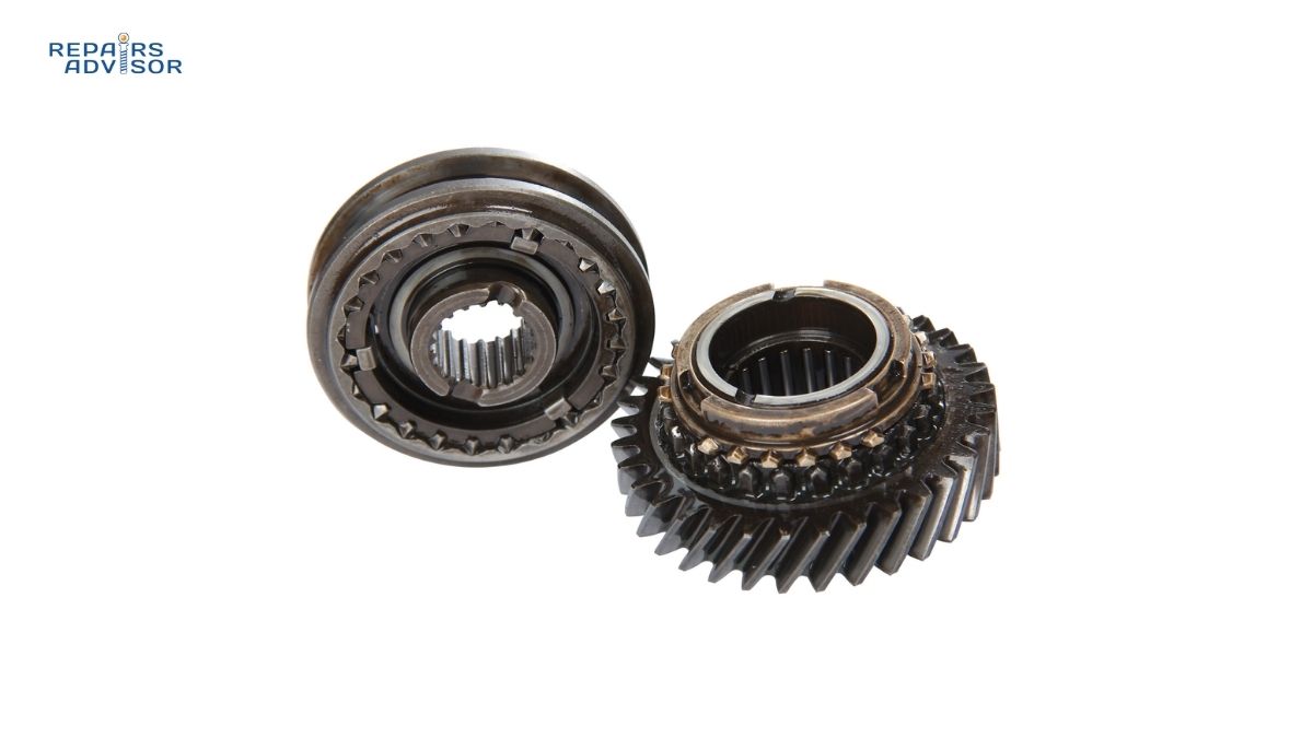
A synchronizer (commonly called a “synchro”) is a mechanical device that equalizes the rotational speeds of transmission components before gears engage. Think of it as an automatic speed-matching system that performs the job skilled drivers once did manually through double-clutching. Every time you shift gears in a modern manual transmission, synchronizers work behind the scenes to make that shift smooth and damage-free.
The synchronizer’s job exists because of a fundamental characteristic of manual transmissions: the gears are in constant mesh with each other, spinning freely on the output shaft until you select them. When you want to change gears, you need to lock your chosen gear to the shaft so it can transmit power. But there’s a problem—the gear and the shaft are usually spinning at different speeds. If you tried to force them together without speed matching, the dog teeth (engagement teeth on the gear and sleeve) would clash violently, creating that grinding noise and potentially chipping or breaking the hardened steel teeth.
Synchronizers solve this problem elegantly. Positioned between adjacent gear pairs (1st-2nd, 3rd-4th, 5th-6th), each synchronizer assembly mounts directly on the transmission output shaft. Most modern transmissions have three or four synchronizer assemblies, with each controlling engagement for two gears—one on either side. The reverse gear may or may not have a synchronizer depending on the transmission design, since reverse typically requires the vehicle to be stationary.
The historical context makes synchronizers’ importance clear. In pre-synchronizer transmissions (common through the 1920s and still used in some heavy trucks today), drivers had to double-clutch: press the clutch, shift to neutral, release the clutch, blip the throttle to match engine speed, press the clutch again, and shift into gear. This technique required skill, practice, and precise timing. Get it wrong, and you’d grind gears or lurch the vehicle. The introduction of synchronized transmissions eliminated this complexity, making manual transmissions far more user-friendly and reliable.
Understanding the relationship between synchronizers and the broader manual gearbox operation provides crucial context. The transmission input shaft receives power from the engine through the clutch, spinning a layshaft (countershaft) that meshes with all the gears. These gears spin freely on the output shaft until the synchronizer locks one of them in place, creating the mechanical connection that transmits power to the wheels at the selected gear ratio.
Synchronizer Components and Construction
A synchronizer assembly consists of multiple precision-engineered components working together to achieve speed synchronization and mechanical engagement. Understanding each part’s role reveals the elegant engineering that makes smooth shifts possible.
Hub Assembly
The hub forms the synchronizer’s foundation, splined directly to the transmission output shaft with a tight interference fit. This permanent connection means the hub always rotates at exactly the same speed as the output shaft—there’s no slippage or independent movement. The hub features external splines that allow the sleeve to slide over it while maintaining rotational connection, plus machined slots that house the spring-loaded keys or struts.
Manufacturers typically forge or sinter the hub from high-strength steel alloy, then heat-treat it to withstand the tremendous forces generated during aggressive shifting. The hub rarely fails unless subjected to severe abuse like power-shifting (shifting without using the clutch) or sustained operation with a dragging clutch. Quality hubs undergo precision machining to ensure perfect spline engagement and proper alignment with other synchronizer components.
Sleeve (Shift Collar)
The sleeve slides along the hub’s external splines, moved by the shift fork that connects to your gear selector. External teeth machined around the sleeve’s middle section mesh with the shift fork, while internal splines engage the hub splines. The sleeve ends feature dog teeth—hardened, squared-off projections designed to lock into matching teeth on the gear.
When the transmission is in neutral, the sleeve sits centered on the hub between two gears. Moving the gear selector pushes the sleeve toward one gear or the other, first activating the synchronization process, then engaging the dog teeth to mechanically lock the gear to the shaft. The sleeve must be strong enough to transmit full engine torque without deflection while sliding smoothly during shifts. Back tapers machined on the dog teeth help prevent accidental disengagement under load.
Blocking Rings (Blocker Rings / Baulk Rings)
The blocking ring is the synchronizer’s critical friction component—where speed matching actually occurs. These rings sit between the synchronizer hub and each gear, featuring a cone-shaped internal surface that matches a corresponding cone machined on the gear itself. When you initiate a shift, the blocking ring contacts the gear’s cone, and friction between these surfaces generates the torque needed to equalize speeds.
Traditional blocking rings were machined from brass, chosen for its excellent friction characteristics and ease of manufacturing. The internal cone surface featured fine grooves cut in a spiral pattern, increasing surface area and improving friction grip. However, brass wears relatively quickly, especially in high-performance or heavy-duty applications. Modern transmissions increasingly use advanced materials: molybdenum-coated steel for commercial vehicles handling high torque, sintered metal compositions offering excellent wear resistance, carbon-based friction materials in performance applications, and specialized phenolic materials in some Japanese transmissions.
The blocking ring also features external teeth with unique pointed profiles. These teeth initially block the sleeve from passing through while speeds are mismatched. Only when synchronization is nearly complete do the teeth align properly, allowing the sleeve to slide past and engage the gear. This mechanical blocking function prevents premature engagement that would cause grinding.
Synchronizer Keys, Balls, or Struts
These small components hold the sleeve centered on the hub when the transmission is in neutral, pushed outward by springs compressed within the hub. During a shift, as the sleeve moves toward a gear, the keys or struts maintain pressure against the blocking ring, ensuring consistent friction contact for speed matching. Some designs use simple balls, others use more sophisticated strut mechanisms, but all serve the same fundamental purpose.
The spring pressure must be carefully calibrated—too weak, and the blocking ring won’t maintain adequate friction contact; too strong, and shifts become excessively hard. Most synchronizers use multiple keys or struts (typically three) positioned evenly around the circumference to balance forces and prevent binding.
Multi-Cone Synchronizers
High-performance transmissions and lower gears handling large torque loads often employ multi-cone synchronizers featuring two or three friction surfaces instead of one. A multi-cone design might include an outer cone, inner cone, and the blocking ring, all creating friction simultaneously. This multiplies the effective friction area, enabling faster synchronization and higher torque capacity.
Multi-cone synchronizers became popular in performance vehicles where aggressive downshifts at high RPM differentials would overwhelm single-cone designs. You’ll typically find them on 1st and 2nd gears, where the speed differential between adjacent gears is largest. The TREMEC Magnum 6-speed, for example, uses triple-cone synchronizers on 1st gear to handle the massive synchronization task of matching shaft speeds from neutral to first gear at vehicle speeds up to 15-20 mph.
The relationship between synchronizers and clutch systems is critical—a properly functioning clutch must fully disengage the engine from the transmission, allowing the synchronizer to work with minimum resistance. If the clutch drags (doesn’t fully disengage), it continues driving the input shaft, forcing the synchronizer to overcome additional friction and dramatically accelerating wear.
How Synchronizers Work: Step-by-Step Operation
The synchronization process happens quickly—typically in 0.1 to 0.5 seconds—but involves a precisely choreographed sequence of mechanical events. Understanding each step reveals why proper technique matters and what goes wrong when synchronizers fail.
Pre-Shift Condition
Before you begin a shift, your transmission is in a specific state: the clutch is engaged, connecting engine power to the transmission input shaft. The currently selected gear is locked to the output shaft by its synchronizer sleeve. All other gears spin freely on the output shaft, driven by the layshaft but not connected to transmit power. The output shaft rotates at a speed determined by vehicle speed and the current gear ratio.
Here’s the fundamental problem: the gear you want to select next is spinning at a different speed than the output shaft. In an upshift (say, 2nd to 3rd), the next gear spins slower than the output shaft. In a downshift (3rd to 2nd), the next gear spins faster. The synchronizer must equalize these speeds before engagement can occur.
Step 1: Clutch Disengagement
When you press the clutch pedal, you’re disconnecting the engine from the transmission. The clutch disc separates from the flywheel and pressure plate, allowing the input shaft and layshaft to decelerate (in an upshift) or continue spinning at their current speed (in a downshift) while the engine speed changes independently. The output shaft continues rotating at vehicle speed, driven by the wheels through the differential and driveshaft.
Full clutch disengagement is critical. If the clutch doesn’t fully release, it continues transmitting some engine torque to the transmission, forcing the synchronizer to work against this additional resistance. This is called a “dragging clutch” and is a primary cause of premature synchronizer wear.
Step 2: Shift Fork Movement Begins
As you move the gear selector, mechanical or hydraulic linkage moves the appropriate shift fork. Each synchronizer has its own fork, positioned in a groove machined around the sleeve’s exterior. The fork slides the sleeve along the hub toward the desired gear. The synchronizer keys or struts, pressed against the sleeve by internal springs, move with it.
The sleeve begins traveling from its centered neutral position toward one of the two gears the synchronizer controls. As it moves, it first pushes against the keys or struts, which in turn push against the blocking ring, moving it toward the gear.
Step 3: Blocker Ring Initial Contact
The blocking ring reaches the gear first—this is by design. The ring’s internal cone contacts the matching cone surface machined on the gear, and friction immediately begins generating torque between them. This initial contact creates significant resistance; you’ll feel this in the shift lever as the characteristic “bite” or slight resistance before the shift completes.
Crucially, the blocking ring’s external teeth are now misaligned with the sleeve’s internal path. The pointed tooth design creates a mechanical block, preventing the sleeve from sliding past the ring while speeds are still mismatched. This blocking action is the synchronizer’s fail-safe mechanism—it’s physically impossible to engage the gear prematurely and cause grinding.
Step 4: Speed Synchronization
With the blocking ring pressed firmly against the gear cone, friction between the surfaces generates torque that adjusts the output shaft speed to match the gear speed. The physics involves the coefficient of friction between the cone surfaces, the normal force pressing them together, and the effective radius of the cone.
In an upshift, the output shaft (spinning fast) must slow down to match the slower next gear. Friction between the cones acts as a brake on the output shaft. The energy dissipates as heat—synchronizers get quite hot during operation, especially during aggressive driving.
In a downshift, the output shaft (spinning slowly relative to vehicle speed in the higher gear) must speed up to match the faster lower gear. The gear, driven faster by the layshaft, accelerates the output shaft through friction at the cone interface. This is why downshifts take slightly longer to synchronize than upshifts—you’re adding energy rather than simply dissipating it.
The synchronization time depends on several factors: the RPM difference between components (larger differences take longer), the friction coefficient of the cone materials, the cone surface area and angle, and the force pressing the cone surfaces together. Multi-cone synchronizers synchronize faster because they have more friction surface area working simultaneously.
Step 5: Speed Match and Ring Alignment
As the speeds equalize (typically within 50-100 RPM of each other), the friction torque at the cone interface drops. With reduced resistance, the blocking ring rotates slightly, allowing its external teeth to align with the grooves in the sleeve. This alignment is the mechanical signal that synchronization is complete—the blocking ring essentially “permits” the sleeve to continue moving.
The blocker ring teeth have specifically engineered profiles—slightly pointed or chamfered—that guide the sleeve through as they align. This design prevents binding and ensures smooth engagement even when alignment isn’t perfectly precise.
Step 6: Sleeve Engagement
With the blocking ring teeth now aligned, the sleeve continues sliding toward the gear. The blocker ring acts as an alignment ramp, guiding the sleeve’s dog teeth toward the gear’s dog teeth. As the sleeve reaches full travel, its dog teeth mesh with the corresponding teeth on the gear’s face.
This engagement creates a positive mechanical connection—the gear is now locked to the output shaft through the sleeve and hub. The dog teeth are square-cut and hardened, designed to transmit full engine torque without deflecting or wearing. Back tapers on the teeth (slight angles on the sides) help keep the teeth engaged under load, preventing accidental disengagement.
Step 7: Clutch Re-Engagement and Power Transfer
With the new gear successfully engaged, you release the clutch pedal. The clutch disc reconnects to the flywheel and pressure plate, restoring the mechanical connection between engine and transmission. Engine power now flows through the clutch, input shaft, layshaft, the newly selected gear, sleeve, hub, output shaft, and finally to the wheels.
The shift is complete. The synchronizer remains in this engaged position, holding the gear locked to the shaft, until you initiate the next shift. The springs and keys hold the sleeve firmly in position, preventing accidental disengagement.
The Detent System
Most transmissions incorporate detents—spring-loaded balls or pins that drop into grooves machined on the shift rails or synchronizer sleeves. These detents serve multiple purposes: they hold gears in the engaged position, prevent accidental gear disengagement from vibration, create the tactile “notches” you feel through the shifter, and require deliberate force to move out of gear.
When you feel the shift lever “click” into place, you’re feeling the detent ball dropping into its groove. Good detent design provides positive feedback that the gear is fully engaged without making shifts excessively notchy or difficult.
Understanding this complete process reveals why certain problems occur. Grinding during shifts means the synchronizer isn’t completing speed matching before the sleeve tries to engage—either the blocker ring is worn and can’t generate sufficient friction, or you’re forcing the shift too quickly. Hard shifting means excessive friction somewhere in the system, possibly from contaminated fluid, damaged blocker rings, or a dragging clutch. The better you understand normal operation, the more quickly you can identify abnormal conditions.
Double-Clutching vs. Synchronizers
To truly appreciate synchronizers, it helps to understand the technique they replaced. Double-clutching is a manual speed-matching method that was mandatory before synchronizers existed and is still useful in specific situations today.
The Double-Clutching Technique
Double-clutching involves pressing the clutch twice during each shift, with a specific sequence in between:
- Press the clutch pedal and shift to neutral
- Release the clutch pedal (engine now reconnected to transmission in neutral)
- Blip the throttle (for downshift) or wait for engine speed to drop (for upshift)
- Press the clutch pedal again
- Shift into the desired gear
- Release the clutch pedal
The critical step is #3, where you manually adjust engine speed to match what the transmission speed will be in the next gear. For a downshift, you “blip” the throttle—give it a quick jab—to raise engine RPM. For an upshift, you wait briefly for engine speed to drop naturally. This speed matching is exactly what the synchronizer does automatically.
Why It Was Necessary
Early transmissions had gears with straight-cut dog teeth designed to slide in and out of engagement. Without synchronizers, these teeth would clash violently if speeds weren’t matched. Skilled drivers could double-clutch seamlessly, making perfectly smooth shifts by developing an intuitive feel for the required engine speeds. Novice drivers ground gears constantly, causing expensive damage.
Commercial truckers often learned to “float” gears—shifting without using the clutch at all, purely by matching engine and transmission speeds through throttle control and timing. This required even more skill but was faster and reduced clutch wear on heavy-duty trucks that didn’t have synchronized transmissions.
Modern Applications
In modern synchronized transmissions, double-clutching is unnecessary for normal driving. The synchronizers automatically match speeds faster and more consistently than most drivers can manually. However, double-clutching still has specific applications:
Downshifting to first while moving: Many transmissions have weak or no synchronization on 1st gear, assuming you’ll only select 1st from a stop. Double-clutching helps engage 1st smoothly if you need to downshift while rolling at low speed.
Worn synchronizers: If your blocker rings are worn and causing grinding, double-clutching reduces the synchronizer’s workload by pre-matching speeds. This can extend the time before transmission rebuild is necessary.
Performance driving: Race drivers often double-clutch on downshifts because it’s faster than waiting for synchronization. By blipping the throttle to match speeds perfectly, they eliminate synchronization time entirely. This technique (often called “heel-toe” because you blip the throttle with your heel while braking with your toe) is standard in motorsports.
Extending synchronizer life: Some enthusiasts double-clutch regularly to reduce wear on synchronizer components, particularly in vehicles they plan to keep long-term. The technique does reduce blocker ring wear, though the benefit is modest with modern materials.
Heavy commercial vehicles: Some commercial trucks, particularly older models, still use non-synchronized “crash boxes” requiring double-clutching or floating gears for all shifts.
The relationship between clutch systems and synchronizers can’t be overstated. Whether you double-clutch or rely on synchronizers, the clutch must fully disengage. A dragging clutch—whether from worn components, air in hydraulic clutch lines, or improper adjustment—makes both techniques difficult and accelerates synchronizer wear dramatically.
Synchronizer Wear and Failure Symptoms
Synchronizers are wear items. Like brake pads, clutches, and tires, they gradually degrade with use and eventually require replacement. Understanding wear patterns and recognizing symptoms early can prevent being stranded and minimize secondary damage.
Progressive Wear Patterns
Synchronizer wear typically follows a predictable progression. The blocker ring’s friction surface experiences the most wear—the cone surface gradually becomes smoother as the friction material wears away. The fine grooves cut into the surface become shallow, reducing the effective friction area. The cone angle itself may become rounded rather than maintaining its precise taper.
As friction capability decreases, the synchronizer takes longer to match speeds. You might not notice this at first, especially during gentle shifts. But during aggressive shifts with large RPM differentials—like a 4th-to-2nd downshift for rapid acceleration—the worn synchronizer can’t synchronize speeds quickly enough. The blocker ring teeth unlock prematurely, allowing the sleeve to attempt engagement before speeds are matched, resulting in grinding.
The typical failure sequence progresses like this:
- Early stage: Grinding only during fast, high-RPM shifts (you can avoid it by shifting more slowly)
- Middle stage: Grinding becomes more frequent, occurring during normal shifts
- Late stage: Grinding on all shifts into that gear, even slow, gentle ones
- Failure: Unable to engage gear at all; gear “refuses” engagement
Since each gear has its own synchronizer or shares one with an adjacent gear, wear typically affects specific gears first. The gears you use most—usually 2nd and 3rd—wear fastest. 1st gear synchronizers often wear quickly because they handle the largest speed differentials, especially if you downshift into 1st while moving.
Grinding Noises
The classic symptom of synchronizer wear is grinding during shifts. This metallic crunching sound is the dog teeth on the sleeve and gear clashing because speeds haven’t been matched. The sound indicates metal-on-metal contact between hardened steel components—continued grinding chips and damages these teeth, potentially requiring complete transmission rebuild rather than just synchronizer replacement.
Grinding typically appears first during downshifts because these require adding energy to the system (speeding up the output shaft). The worn blocker ring can’t generate sufficient torque to accelerate the shaft quickly enough. Upshifts may remain smooth longer because they only require dissipating energy (slowing the shaft), which is mechanically easier.
If grinding occurs only when the transmission is cold but improves when warm, this often indicates the wrong fluid type. Some fluids become too thick when cold, preventing the synchronizer from operating correctly. Alternatively, if grinding worsens when hot, this might indicate fluid breakdown or contamination.
Hard or Resistant Shifting
Increased resistance when moving the gear selector suggests excessive friction somewhere in the system. You might feel like the gear is “blocked” or that you need to push harder than normal to complete the shift. This can result from several causes:
The blocker ring may be damaged or contaminated, creating excessive friction at the cone interface. The sleeve might be binding on the hub splines due to worn or damaged splines. Contaminated transmission fluid—especially with metal particles from other worn components—increases friction throughout. A dragging clutch forces the synchronizer to work against engine torque, creating resistance.
Experienced mechanics can often diagnose which component is causing resistance based on how it feels, but this requires significant experience with that particular transmission type.
Gear Rejection and Popping Out
When a gear “refuses” to engage, bouncing the shift lever back toward neutral, the synchronizer has failed to complete its job. The blocker ring teeth aren’t aligning properly, preventing the sleeve from passing through to engage the gear. You might need multiple attempts to complete the shift, waiting longer each time for the synchronizer to match speeds.
If the transmission pops out of gear under load—spontaneously returning to neutral while driving—this indicates the synchronizer can’t hold engagement. The dog teeth may be worn or damaged, allowing them to disengage under torque. This is dangerous; imagine suddenly losing power while accelerating to merge onto a highway.
Gear-specific symptoms are common. If 2nd gear always grinds but 3rd is fine, the 2nd gear synchronizer (or the 1-2 synchronizer assembly if they share one) is worn. If both gears controlled by one synchronizer assembly show symptoms, the blocker rings for both are likely worn.
Root Causes of Premature Wear
Understanding what causes premature synchronizer failure helps you avoid it:
Aggressive shifting: Speed-shifting, power-shifting (shifting without the clutch), or forcing shifts before synchronization completes puts excessive stress on blocker rings. The friction materials overheat and wear rapidly.
Clutch problems: A dragging clutch is probably the most common cause of premature synchronizer failure. If the clutch doesn’t fully disengage, it continues driving the input shaft, forcing the synchronizer to overcome this torque. Many transmission rebuilds performed “for synchronizer failure” were actually caused by a worn clutch that should have been replaced earlier.
Wrong transmission fluid: Using incorrect fluid viscosity or type can devastate synchronizers. Some automatic transmission fluids contain friction modifiers that make synchronizers slip excessively. Synthetic fluids that are too “slippery” reduce the coefficient of friction at the cone interface. Always use exactly the fluid type specified by the manufacturer.
Contamination: Metal particles from other worn transmission components act as abrasives, accelerating synchronizer wear. Water contamination from failed seals breaks down fluid additives and causes corrosion.
Normal wear: Beyond 150,000-200,000 miles, synchronizer wear is normal and expected. Some transmissions have remarkably durable synchronizers; others wear faster depending on design and materials used. The fluid quality makes a significant difference—religiously changing transmission fluid at recommended intervals significantly extends synchronizer life.
Diagnosis and Repair Considerations
Diagnosing synchronizer problems requires careful analysis because symptoms can mimic other issues. Repair is labor-intensive and expensive, making accurate diagnosis critical.
Diagnostic Process
Start with symptom analysis. Which gear or gears are affected? Does the problem occur during upshifts, downshifts, or both? Is grinding present at all speeds or only during aggressive shifts? Does the problem change with temperature—better when warm, worse when cold, or vice versa? Has any recent work been done on the clutch, transmission, or shifter linkage?
Clutch system verification is absolutely critical. Many transmissions are unnecessarily disassembled “for synchronizer problems” when the actual issue is a dragging clutch. Test for clutch drag with this simple check:
- Engine running, parking brake engaged
- Press clutch pedal fully and hold
- Wait 5-10 seconds (allows input shaft to stop spinning)
- Attempt to shift into 1st gear
If you hear grinding when shifting into 1st, or if shifting is difficult, the clutch is dragging—not fully disengaging. This must be fixed before condemning synchronizers. Check clutch pedal free play adjustment (if mechanical), verify proper hydraulic system operation and bleeding, and confirm no clutch disc hub breakage or pressure plate warpage.
Fluid inspection provides crucial information. Check the transmission fluid level first—low fluid can cause shifting problems that mimic synchronizer failure. Drain a sample and inspect for metal particles. Fine dust is normal wear, but chunks or significant metal content indicate serious internal damage. Smell the fluid—burnt odor suggests overheating. Wrong fluid color (checking against manufacturer specifications) might indicate someone used incorrect fluid.
Shifting pattern analysis helps isolate the problem. If 2nd gear grinds but 3rd doesn’t, the issue is likely specific to the 2nd gear synchronizer. If multiple gears grind, you might have a clutch problem affecting all shifts. If all shifts are hard but don’t grind, look for external linkage problems or wrong fluid viscosity.
Professional Diagnosis and Repair
Definitive synchronizer diagnosis requires transmission disassembly. There’s no external test that can confirm blocker ring wear or measure remaining friction material. Experienced transmission technicians can make educated guesses based on symptoms and history, but complete certainty comes only from internal inspection.
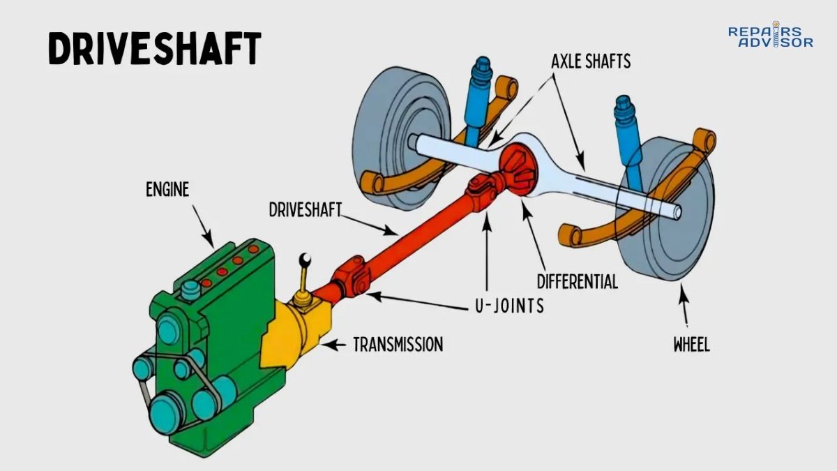
Transmission removal is labor-intensive. On rear-wheel-drive vehicles, it’s relatively straightforward—drop the driveshaft, remove the crossmember, disconnect linkage and electrical connections, and pull the transmission. Front-wheel-drive vehicles present more challenges, often requiring engine removal or partial removal to access transmission mounting points. Labor time typically runs 6-12 hours depending on vehicle design.
Once removed, complete disassembly reveals the synchronizers’ condition. Technicians measure blocker ring friction material remaining, inspect dog teeth for damage, check hub and sleeve spline wear, and examine bearings, shafts, and gears for damage. Often, if one synchronizer is worn, others are close behind—comprehensive rebuilds usually replace all synchronizers simultaneously.
Cost Considerations
Transmission synchronizer replacement costs vary significantly by vehicle:
Labor: $800-$1,500+ for transmission removal, disassembly, reassembly, and reinstallation Parts: $300-$800 per synchronizer assembly, plus bearings ($100-$300), seals and gaskets ($100-$200), fluid ($50-$150) Total typical cost: $1,500-$3,500 for synchronizer replacement
These costs assume the transmission case, shafts, and gears are in good condition. If other internal damage is found—worn bearings, damaged gears, or scored shafts—costs escalate dramatically. At this point, replacement with a remanufactured transmission might be more economical.
Remanufactured transmissions with warranty typically cost $1,500-$3,000 plus installation labor. If your transmission has high mileage or multiple issues, replacement might be the better value proposition.
DIY vs. Professional Service
Transmission synchronizer replacement is not suitable for DIY unless you have significant mechanical experience, specialized tools, and a proper workspace. The challenges include:
Transmission removal requires heavy lifting equipment—transmissions weigh 80-150+ pounds. Attempting to support this weight manually risks serious injury and transmission damage.
Special tools are necessary: torque wrench for precise bearing preload adjustment, snap ring pliers for internal retainer removal, bearing pullers and drivers, transmission jack for safe removal and installation, dial indicator for endplay measurement, and service manual with exact specifications.
Precise assembly is critical. Bearing preload must be set exactly to specifications. Synchronizer components must be oriented correctly. Shim packs may need adjustment. Gear tooth mesh patterns should be verified. Mistakes during reassembly can cause immediate failure or premature wear.
Safety considerations are significant. Transmission fluid contains additives and metal wear particles requiring proper disposal per environmental regulations. The transmission weight poses crush hazard if not properly supported. Some transmissions contain pressure-sealed components that can discharge forcefully if improperly disassembled.
For these reasons, synchronizer replacement is strongly recommended for professional service only. However, there are DIY-friendly maintenance tasks: transmission fluid changes, external linkage adjustment, and clutch inspection can all be performed without transmission removal and help prevent synchronizer problems.
Extending Synchronizer Life
While synchronizers will eventually wear out, proper technique and maintenance can significantly extend their service life. The difference between synchronizers lasting 150,000 miles versus 250,000+ miles often comes down to how you drive and maintain the vehicle.
Proper Shifting Technique
Complete clutch engagement is the single most important factor. Press the clutch pedal fully to the floor every time you shift. Partial clutch disengagement leaves some engine torque connected, forcing synchronizers to work harder. Hold the pedal down until the shift is complete—releasing it during the shift defeats the synchronizers’ purpose.
Avoid riding the clutch pedal. Resting your foot on the pedal applies slight pressure to the clutch release bearing, which can cause the clutch to partially disengage. This subtle slippage increases synchronizer workload and causes premature wear.
Shift with deliberate speed, not excessive speed. Many drivers pride themselves on lightning-fast shifts, but this stresses synchronizers unnecessarily. A shift that takes 0.4 seconds instead of 0.2 seconds feels the same to passengers but gives synchronizers adequate time to complete their job. Feel for the synchronizer “bite” during each shift—that slight resistance as the blocker ring contacts the gear cone—and don’t force past it prematurely.
Rev-matching on downshifts is an advanced technique that reduces synchronizer workload. When downshifting, blip the throttle while in neutral (with clutch engaged) to raise engine RPM closer to what it will be in the lower gear. This reduces the speed differential the synchronizer must overcome. Professional drivers do this instinctively; anyone can learn with practice. The technique is also called “heel-toe” because you use your heel on the throttle while braking with your toe, allowing simultaneous braking and rev-matching.
Transmission Fluid Maintenance
Use exactly the specified fluid type. This cannot be emphasized enough. Some transmissions require specific “synchromesh” fluid formulated for manual transmissions with brass or sintered metal synchronizers. Others may specify gear oil with specific GL ratings. Some actually require automatic transmission fluid. Using the wrong type causes synchronizer slipping and premature wear.
Don’t mix fluid types—if you’re topping off, use the same type already in the transmission. Don’t substitute “equivalent” fluids without verifying they meet manufacturer specifications. The few dollars saved on fluid isn’t worth thousands in transmission repairs.
Change fluid at recommended intervals. Many manufacturers specify 30,000-60,000 mile intervals for manual transmission fluid changes. Some claim “lifetime” fluid, but experienced mechanics universally recommend changing it at 60,000-100,000 miles maximum. Fresh fluid contains active friction modifiers and detergents that protect synchronizers. Old fluid accumulates metal particles, loses its additives, and becomes more viscous.
Fluid condition inspection during changes provides early warning. Excessive metal particles, burnt smell, or darkened color indicate internal wear that may progress to synchronizer failure.
Driving Habits for Longevity
Allow cold transmission to warm before aggressive shifting. Transmission fluid becomes thick when cold, affecting synchronizer operation. During the first few miles of driving, shift gently and avoid high-RPM shifts. This is particularly important in cold weather. Once the transmission reaches operating temperature (usually 10-15 minutes of driving), normal shifting is fine.
Never force shifts. If a gear won’t engage smoothly, don’t force it. Release the clutch momentarily, let the transmission go back to neutral, then retry the shift. Forcing engagement damages dog teeth and blocker rings. A brief pause allows synchronization to complete.
Avoid excessive downshifting. While downshifting for engine braking is fine when done smoothly, repeated aggressive downshifts (like downshifting from 5th to 2nd to slow rapidly) stress synchronizers unnecessarily. Your brakes are designed for slowing the vehicle; save the transmission for normal gear selection.
Don’t shift into 1st gear while moving unless absolutely necessary. Most transmissions have weak or no synchronization on 1st gear, designed for starts from rest. Shifting into 1st at speed can grind severely. If you must downshift to 1st (for example, approaching a stop sign where the light turns green before you stop), do so at very low speed (under 5 mph) and use gentle pressure.
Critical Clutch System Relationship
Everything about synchronizer longevity depends on a properly functioning clutch system. A dragging clutch—even slightly—forces synchronizers to work against engine torque, dramatically accelerating wear. Replace the clutch at the first signs of slippage or difficult disengagement. When replacing the clutch, also replace the release bearing and inspect the pressure plate.
For hydraulically actuated clutches, keep the system properly bled. Air in hydraulic lines prevents full clutch disengagement. For cable-actuated clutches, maintain proper adjustment—excessive free play means incomplete disengagement.
The relationship extends beyond just wear—clutch and synchronizer work as an integrated system. Understanding this connection helps you recognize when clutch problems might be causing what appear to be transmission issues.
Conclusion
Manual transmission synchronizers are masterful examples of mechanical engineering, solving a complex speed-matching problem with elegant simplicity. These friction clutches silently perform their job thousands of times, enabling the smooth, precise shifts we expect from modern manual transmissions. From the brass blocker rings matching component speeds through controlled friction, to the mechanical blocking mechanism preventing premature engagement, every aspect of synchronizer design serves the single purpose of making gear changes smooth and damage-free.
Understanding how synchronizers work provides crucial context for recognizing problems early. That first grinding noise during a fast shift isn’t random—it’s the blocker ring telling you friction material is wearing thin. Hard shifting resistance might indicate contaminated fluid or a dragging clutch, both addressable before synchronizer damage occurs. Gear rejection often means you’re forcing shifts too quickly, not allowing synchronization to complete.
The good news is that proper technique dramatically extends synchronizer life. Fully disengaging the clutch, shifting deliberately rather than forcefully, using correct transmission fluid, and maintaining the clutch system can mean the difference between synchronizers lasting 150,000 miles versus 250,000+ miles. Small habits compound over hundreds of thousands of shifts.
When to seek professional help: If you experience grinding noises during any shift, increasing difficulty engaging specific gears, transmission popping out of gear under load, or persistent hard shifting despite correct fluid, consult a qualified transmission technician promptly. Early intervention prevents minor synchronizer wear from becoming major transmission damage. If you’ve recently had clutch work performed and suddenly develop shifting problems, have the clutch system rechecked—proper clutch operation is absolutely essential for synchronizer longevity.
Why professional service matters: Synchronizer diagnosis requires experience distinguishing transmission problems from clutch issues. Repair demands transmission removal, complete disassembly, and precise reassembly with proper bearing preload and clearances. Attempting DIY synchronizer replacement without specialized tools and knowledge risks transmission damage, personal injury, and expensive mistakes. Professional technicians have the experience to accurately diagnose root causes, preventing repeat failures.
Final recommendation: Treat your transmission gently, shift deliberately, use the specified fluid, and maintain the clutch system properly. Your synchronizers will reward you with hundreds of thousands of smooth, reliable shifts. At the first sign of abnormal operation, seek professional diagnosis promptly. The relatively minor cost of early intervention is insignificant compared to complete transmission rebuild or replacement.
Critical safety reminder: Manual transmission service involves components weighing 80-150+ pounds, transmission fluid requiring proper disposal, and precise assembly procedures affecting vehicle safety. Synchronizer replacement requires professional-grade equipment and expertise. Always consult qualified transmission specialists for diagnosis and repair. Improper repairs can result in transmission failure while driving, creating dangerous situations for you and others on the road.
Related Reading:
- How Transfer Cases Work: 4WD Operation
- How AWD Systems Work: All-Wheel Drive Coupling
- How Drive Shafts Work: Power Transmission
- How CV Joints Work: Constant Velocity Power Transfer
- How Differential Systems Work: Torque Distribution
- How Limited Slip Differentials Work: Enhanced Traction
- How Planetary Gearsets & Valve Bodies Work: Automatic Transmission Fundamentals
