Why the Crankshaft Is Critical for Engine Performance
The crankshaft serves as the heart of every internal combustion engine, converting the linear motion of pistons into the rotational motion needed to power your vehicle. Without proper crankshaft function, no engine can operate, making it perhaps the most critical component in the entire powertrain system.
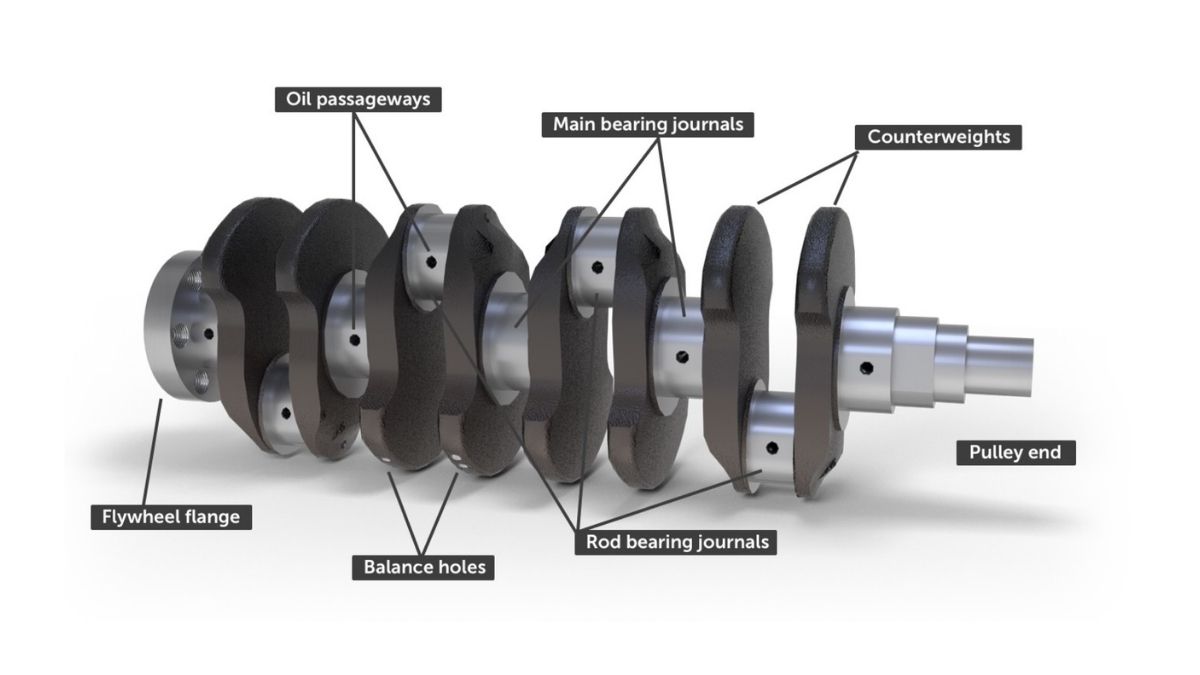
This precisely machined component transforms explosive combustion forces into smooth rotational power through a complex system of journals, counterweights, and connecting points. The crankshaft’s main bearings support the rotating assembly while crankshaft journals provide connection points for the connecting rods, creating the mechanical advantage needed to convert reciprocating motion into continuous rotation.
Quick Facts:
- Function: Converts linear piston motion to rotational output
- Category: Primary engine performance component
- Maintenance Level: Professional service recommended
- Failure Impact: Complete engine shutdown
Modern engines depend on precise crankshaft timing for optimal performance, fuel efficiency, and emissions control. The engine management system monitors crankshaft position through sensors to control ignition timing, fuel injection, and valve operation with microsecond precision.
Safety Note: Crankshaft work requires specialized tools and precision measurement equipment. Given the critical nature of this component, professional diagnosis and service ensure safety and proper engine function.
Crankshaft Parts and Construction Explained
Core Structural Elements
The crankshaft’s forged or cast steel construction creates the strength needed to handle tremendous combustion forces while maintaining precision tolerances measured in thousandths of an inch.
Main Journals: These precision-ground surfaces rotate within the main bearings mounted in the engine block. Typically measuring 2-3 inches in diameter, main journals must maintain perfect roundness and surface finish to ensure proper lubrication and prevent wear.
Rod Journals: Offset from the main journals, these surfaces connect to the connecting rods that transfer piston force. The offset distance, called the stroke, determines engine displacement and directly affects torque characteristics.
Counterweights: These precisely calculated masses balance the rotating assembly, reducing vibration and stress throughout the engine. Advanced engines may use balance shafts for additional smoothness, but proper counterweight design handles most vibration control.
Precision Engineering Features
Oil Passages: Internal drilling connects the main journals to rod journals, ensuring continuous lubrication under all operating conditions. These passages work with the oil pump to maintain critical oil film thickness between moving surfaces.
Thrust Surfaces: Special flanged bearings or integral thrust surfaces control crankshaft end play, preventing axial movement that could damage seals or affect timing. Thrust bearing wear can indicate transmission or clutch problems in manual transmission vehicles.
Seal Surfaces: Front and rear seal journals provide mounting points for oil seals that prevent leakage while allowing rotation. These areas require special attention during service, as improper installation can cause persistent oil leaks.
Material Science and Manufacturing
Modern crankshafts use forged steel for high-performance applications or nodular iron castings for standard engines. Forged crankshafts offer superior strength and fatigue resistance, essential for high-power or high-RPM applications.
Surface treatments include nitriding or induction hardening of journal surfaces, creating wear-resistant surfaces while maintaining tough, flexible cores. This dual-hardness design provides longevity under extreme conditions while preventing catastrophic failure.
How the Crankshaft Works: Step-by-Step Operation
The Four-Stroke Conversion Process
Step 1: Power Stroke Initiation Combustion forces drive the piston downward with tremendous force, typically 3,000-5,000 pounds in modern engines. The connecting rod transfers this linear force to the offset rod journal, creating rotational torque through mechanical advantage.
Step 2: Momentum and Energy Storage The flywheel connection stores rotational energy during the power stroke, providing momentum to carry the crankshaft through the three non-power strokes. This energy storage and release creates smooth power delivery despite the intermittent nature of combustion.
Step 3: Compression and Exhaust Work During compression and exhaust strokes, stored flywheel energy drives the crankshaft, forcing pistons upward against compression pressure and exhaust back-pressure. The timing system ensures precise coordination between crankshaft rotation and valve operation.
Step 4: Intake Stroke Completion Crankshaft rotation creates downward piston motion that draws the air/fuel mixture into the cylinder through the intake valve. The fuel injection system times fuel delivery based on crankshaft position for optimal combustion.
Multi-Cylinder Coordination
In multi-cylinder engines, the crankshaft coordinates power strokes from different cylinders to provide smooth operation. The crankshaft position sensor informs the engine management system of exact rotational position, enabling precise timing of ignition and fuel injection events.
Firing Order Optimization: Engineers design specific firing orders to minimize vibration and maximize smoothness. The crankshaft’s journal arrangement ensures that power strokes occur at optimal intervals, typically every 90 degrees in four-cylinder engines or every 120 degrees in six-cylinder designs.
Balance and Vibration Control: Counterweight placement counteracts the inertial forces created by reciprocating pistons and connecting rods. First-order and second-order vibrations require different balancing strategies, with some engines using dual counter-rotating balance shafts for maximum smoothness.
Lubrication System Integration
The crankshaft forms the center of the engine’s lubrication system, with pressurized oil flowing through internal passages to lubricate all bearing surfaces. The oil pan collects oil after it lubricates the crankshaft bearings, while the oil pump maintains consistent pressure throughout the system.
Hydrodynamic Bearing Operation: At operating RPM, the crankshaft literally floats on a thin film of oil, never making direct contact with bearing surfaces. This hydrodynamic lubrication prevents metal-to-metal contact and ensures long component life when properly maintained.
Crankshaft Location and Access Guide
Engine Bay Location and Identification
The crankshaft occupies the lowest portion of the engine block, rotating in main bearing caps or a bedplate structure. While never directly visible without engine disassembly, several external components provide access points and reference landmarks.
Visual Identification Markers:
- Front Crankshaft Pulley: The large pulley at the front of the engine drives belts for accessories and provides timing reference marks
- Oil Pan: The lowest point of the engine contains the crankshaft’s rotating assembly
- Transmission Bell Housing: The rear of the crankshaft connects to the transmission through the flywheel or flexplate
Access Requirements and Safety Considerations
Basic Inspection Access (Intermediate DIY Level): Visual inspection of the front crankshaft pulley and seal area requires only basic tools and vehicle lifting equipment. Check for oil leaks, pulley wobble, or timing mark visibility during routine maintenance.
Service Access Requirements (Professional Level): Internal crankshaft service demands complete engine disassembly, precision measuring tools, and specialized equipment for bearing installation. This level of work requires professional facilities and expertise.
Critical Safety Equipment:
- Proper engine lifting equipment rated for complete engine weight
- Precision measuring instruments (micrometers, dial indicators)
- Clean room environment to prevent contamination
- Torque specifications and sequence documentation
Vehicle-Specific Variations
Front-Wheel Drive Applications: Transverse engine mounting may require transmission removal for rear crankshaft seal access. The manual transmission or automatic transaxle connects directly to the crankshaft through the flywheel or flexplate.
Rear-Wheel Drive Configuration: Longitudinal engine mounting provides better access to both ends of the crankshaft. The flywheel connection transfers power through the transmission to the rear wheels.
All-Wheel Drive Systems: Additional complexity from transfer case connections may require special procedures for crankshaft service. Professional consultation ensures proper service sequences and prevents damage to expensive drivetrain components.
Professional Service Integration
Given the crankshaft’s central role in engine operation, most service requires professional expertise and equipment. However, understanding crankshaft function helps DIY enthusiasts recognize symptoms and communicate effectively with service professionals.
When to Seek Professional Service:
- Unusual engine vibration or knocking sounds
- Metal particles in engine oil
- Timing-related performance issues
- Oil pressure problems
- Engine timing diagnostic codes
Quality service facilities have the specialized tools, clean environments, and precision measuring equipment essential for crankshaft work. The 180-day guarantee available through Repairs Advisor’s customer support ensures access to professional-grade service information when needed.
Professional diagnosis prevents unnecessary work and ensures proper repair procedures. For comprehensive diagnostic and repair information specific to your vehicle, explore our extensive collection of automotive repair manuals covering all major manufacturers including Ford, Toyota, and Honda.
Information provided for reference only. Always consult manufacturer specifications and seek professional guidance for complex engine work. Crankshaft service requires specialized knowledge and equipment beyond typical DIY capabilities.