Every time you turn your steering wheel, a complex geometric relationship determines exactly how your vehicle responds. This relationship, known as steering geometry, involves five fundamental angles that work together to provide predictable handling, maximize tire life, and ensure safe vehicle control. Understanding these angles—camber, caster, toe, kingpin inclination, and scrub radius—along with Ackermann steering principles reveals why some vehicles handle precisely while others wander or wear tires prematurely.
Steering geometry problems typically manifest as pulling to one side, uneven tire wear patterns, or an off-center steering wheel when driving straight. These symptoms indicate that the angular relationship between your suspension components, steering parts, and road surface has deviated from manufacturer specifications. Whether caused by normal component wear, impact events like potholes or curb strikes, or modifications to your vehicle, misaligned geometry compromises both safety and economics. According to the Tire Industry Association, misalignment can reduce tire lifespan by up to 25%, translating to hundreds of dollars in premature replacement costs.
This comprehensive guide examines how each geometry angle affects vehicle behavior, why the Ackermann principle solves the turning radius challenge, and when professional alignment service becomes mandatory. While some inspection is DIY-accessible, the precision required for proper alignment demands specialized equipment and expertise. Before diving into the technical details, understanding the relationship between steering knuckles and rack and pinion steering provides essential context for how geometry angles are physically created and maintained.
Why Steering Geometry Is Critical
Steering geometry defines the angular relationship between your suspension components, steering linkages, wheels, and the road surface. These angles aren’t arbitrary—they’re carefully engineered to provide predictable handling characteristics, maximize tire contact with the road, and ensure straight-line stability. When geometry is correct, your vehicle tracks straight without constant steering corrections, corners predictably, and wears tires evenly across the tread surface. When geometry deviates from specifications, even by small amounts, the effects cascade through handling, tire wear, and fuel efficiency.
The most immediate consequence of misalignment is compromised vehicle control. Incorrect geometry angles cause your vehicle to pull sideways, requiring constant steering corrections to maintain a straight path. This pulling behavior isn’t just annoying—it represents a genuine safety hazard. During emergency maneuvers or in adverse weather conditions, a vehicle with poor geometry responds unpredictably, potentially increasing stopping distances or reducing your ability to avoid obstacles. The steering wheel position itself provides diagnostic information: if your wheel is off-center when driving straight, your toe settings are incorrect relative to the thrust angle.
Steering geometry changes occur through several mechanisms. Normal wear on suspension components like ball joints and bushings allows increased play in the system, gradually altering the precise angles that define proper geometry. Impact events—driving over potholes, striking curbs, or minor collisions—can bend suspension components, immediately throwing geometry out of specification. Vehicle modifications, particularly lifting or lowering, fundamentally alter the suspension geometry in ways that require compensating adjustments. Even simple component replacement during routine maintenance necessitates an alignment check, as new parts may have slightly different dimensions than worn originals.
The economic impact of poor geometry centers on accelerated tire wear. When camber is misaligned, either the inside or outside edge of your tire bears disproportionate load, creating distinctive wear patterns and reducing tire life significantly. Toe misalignment causes an even more rapid wear pattern called feathering, where the tread develops a serrated appearance as the tire constantly scrubs sideways against the direction of travel. This scrubbing not only destroys tires prematurely but also increases rolling resistance, reducing fuel economy. A set of four quality tires costs between $400-800, making premature replacement due to poor geometry an expensive consequence of deferred maintenance. Proper geometry, maintained through regular alignment service, maximizes tire life while ensuring safe, predictable vehicle control. Understanding how wheel bearing systems interact with geometry angles helps explain why bearing wear can also affect alignment.
Professional Note for Intermediate DIYers: While you can inspect for obvious damage and check toe measurements with basic tools, proper alignment requires specialized equipment. Professional alignment machines measure angles to within 0.01° accuracy—precision impossible to achieve with string-and-tape methods. Safety dictates professional service for actual adjustments.
Camber Angle: Vertical Wheel Tilt
Camber represents the angle between your wheel’s centerline and true vertical when viewed from the front or rear of the vehicle. This seemingly simple measurement profoundly affects tire contact patch, cornering performance, and wear patterns. Positive camber occurs when the top of the wheel tilts outward, away from the vehicle’s centerline. Negative camber describes the opposite condition, with the wheel top tilting inward toward the engine or differential. Zero camber means the wheel stands perfectly perpendicular to the road surface, though this ideal is rarely the target specification.
Most modern passenger vehicles run slight negative camber, typically between 0.5° and 2° depending on the suspension design and intended use. This negative camber serves multiple purposes. During straight-line driving, it helps counteract the tendency of suspension components to deflect under load, keeping the tire’s contact patch optimally positioned. More importantly, negative camber dramatically improves cornering performance. As your vehicle leans into a turn, body roll causes the suspension on the outside wheels to compress while the inside suspension extends. Without negative camber, this body roll would tilt the outside wheels onto their outer edges, dramatically reducing the contact patch and available grip. The built-in negative camber compensates for this lean, keeping the outside tire’s tread flatter against the road during cornering.
The MacPherson strut suspension design inherently experiences camber change during suspension travel—a characteristic called camber gain. As the suspension compresses over bumps or during body roll, the camber angle increases (becomes more positive or less negative). Engineers account for this dynamic behavior by setting static camber specifications that optimize the tire’s contact patch across the typical range of suspension movement. Performance vehicles often specify more negative static camber to maintain optimal tire contact at higher cornering speeds where greater suspension travel and body roll occur.
Excessive camber in either direction creates distinctive tire wear patterns. Too much positive camber concentrates load on the outer edge of the tire, creating accelerated wear that appears as smooth, worn tread on the outside while the inside tread remains relatively new. Conversely, excessive negative camber overloads the inner edge, producing the opposite wear pattern. Both conditions reduce tire life substantially and indicate the need for immediate alignment correction. Cross-camber—the difference between left and right side camber—must remain within tight tolerances, typically less than 0.5°, to prevent the vehicle from pulling toward the side with more positive camber.
Camber adjustment methods vary significantly by vehicle design. Many vehicles with strut suspension feature elongated mounting holes in the strut tower or steering knuckle, allowing lateral strut movement to adjust camber. Eccentric bolts or washers on control arm mounting points provide adjustment on double wishbone designs. Aftermarket camber plates offer increased adjustment range for modified vehicles. However, some economy vehicles provide no camber adjustment at all, relying on precise manufacturing tolerances. When these vehicles experience camber problems, only component replacement restores proper geometry. Racing applications may employ as much as -3° to -4° camber, accepting accelerated straight-line tire wear in exchange for maximum cornering grip—a compromise unsuitable for street use.
Beginner-Friendly Explanation: Think of camber like leaning into a turn on a bicycle. The wheel tilts to maintain flat contact with the ground as you corner, providing maximum grip and stability. Your car’s suspension does this automatically through engineered camber angles.
Caster Angle: Steering Axis Tilt
Caster describes the angle of the steering axis relative to vertical when viewed from the side of the vehicle. Unlike camber, which is immediately visible by looking at wheel tilt, caster is less obvious but equally important for steering feel and stability. Positive caster, found on virtually all modern vehicles, means the top of the steering axis tilts toward the rear of the vehicle. This geometry is similar to a bicycle’s front fork, which angles backward from the handlebar to the front wheel. Negative caster, with the top tilting forward, was occasionally used on very old vehicles before power steering became standard but is essentially obsolete in contemporary automotive design.
Positive caster creates a powerful self-centering effect that fundamentally shapes steering behavior. When you turn the steering wheel away from the straight-ahead position, the geometry causes the front of the vehicle to lift slightly against its own weight. This lifting action occurs because the steering axis intersects the ground ahead of where the tire contacts the road, creating mechanical leverage. The vehicle’s weight constantly works to lower itself back to the lowest position—which occurs when the wheels point straight ahead. This weight-induced torque provides the familiar sensation of the steering wheel wanting to return to center after you navigate a turn and begin releasing steering input.
The magnitude of caster angle directly affects steering effort and high-speed stability. Higher caster angles, typically 5-8° on modern vehicles, create stronger self-centering force and improved straight-line stability, particularly at highway speeds. The vehicle resists wandering and feels planted even in crosswinds or over crowned roads. However, this stability comes at the cost of heavier steering effort—more force is required to turn the wheels against the increased centering torque. Before power steering became universal, vehicles used much lower caster angles, sometimes 3-4° or even negative values, to reduce the physical effort required to turn the wheel. Modern hydraulic power steering and electric assist systems easily overcome the heavier steering forces, allowing engineers to specify higher caster for improved stability.
The distance between where the steering axis intersects the ground and where the tire contacts the road is called mechanical trail, and it directly relates to caster angle. Greater positive caster increases this trail dimension, amplifying the self-centering torque. This trail also helps absorb road irregularities transmitted through the steering. When your tire strikes a bump or pothole, the impact forces try to disturb the wheel’s direction. The mechanical trail created by positive caster provides a moment arm that dampens these disturbances, preventing the steering from feeling excessively reactive to every road imperfection. This characteristic explains why vehicles with proper caster track straight over rough roads without requiring constant steering corrections.
Cross-caster—the difference between left and right caster angles—causes the vehicle to pull toward the side with less caster. This pull occurs because the side with less caster generates less self-centering force, effectively creating an imbalance that steers the vehicle in that direction. Unlike camber-induced pull, which can result from tire or suspension issues, caster pull almost always indicates bent suspension components or frame damage. Most vehicles specify identical left and right caster within very tight tolerances, typically 0.5° or less difference. Understanding how the steering column transmits torque helps appreciate why caster angle affects steering feel so dramatically.
Caster adjustment is often limited or impossible on modern unibody vehicles. The caster angle is primarily determined by the position of the upper strut mount relative to the lower control arm attachment point. Moving these mounting locations requires specialized shims or adjustment procedures that many vehicles simply don’t accommodate. When caster is significantly out of specification on a vehicle without adjustment capability, the underlying problem is usually bent suspension components or structural damage requiring parts replacement. On vehicles that do offer caster adjustment, the procedure typically involves moving the strut top mount fore or aft, or using shims at control arm mounting points on older designs.
Professional Insight: The shopping cart analogy perfectly illustrates extreme positive caster. Shopping cart front wheels use a large offset between the swivel pivot and wheel contact point, creating such strong self-centering that the cart naturally tracks straight. Vehicles use the same principle with more moderate caster angles optimized for both stability and steering responsiveness.
Toe Settings: Parallel Alignment
Toe describes whether the front edges of your wheels point toward each other, away from each other, or run perfectly parallel when viewed from above the vehicle. This measurement, though conceptually simple, has the most dramatic effect on tire wear of any alignment angle. Toe can be expressed in degrees or as a linear measurement—typically fractions of an inch representing the difference between the distance measured between the wheel fronts versus the distance between the wheel rears. A perfectly parallel setup has zero toe, meaning the wheels track exactly the same path with no convergence or divergence.
Toe-in, the most common specification for front wheels on passenger vehicles, means the front edges of the wheels point slightly toward the vehicle centerline. Typical toe-in specifications range from 1/32″ to 1/8″ total (measuring both wheels combined), though the exact value is carefully calibrated for each vehicle design. This slight convergence serves several important purposes. Primarily, toe-in compensates for suspension compliance and tire flexibility under normal driving forces. As power is applied and the vehicle accelerates, various forces act on the suspension components and steering linkage, tending to push the wheel fronts outward. The built-in toe-in counteracts this tendency, allowing the wheels to settle into true parallel tracking under actual driving conditions. Additionally, toe-in enhances straight-line stability, giving the vehicle a more settled, predictable feel on the highway.
Toe-out describes the opposite condition, where the front edges of the wheels point away from the centerline. This configuration is occasionally used in racing applications because it creates a more responsive turn-in characteristic—the vehicle reacts more quickly to initial steering input. However, toe-out compromises straight-line stability, making the vehicle feel darty or nervous, particularly at higher speeds. More critically, toe-out dramatically accelerates tire wear through increased scrubbing action. For these reasons, toe-out specifications are rare on street vehicles and, when present, involve very small values carefully balanced against the stability drawbacks.
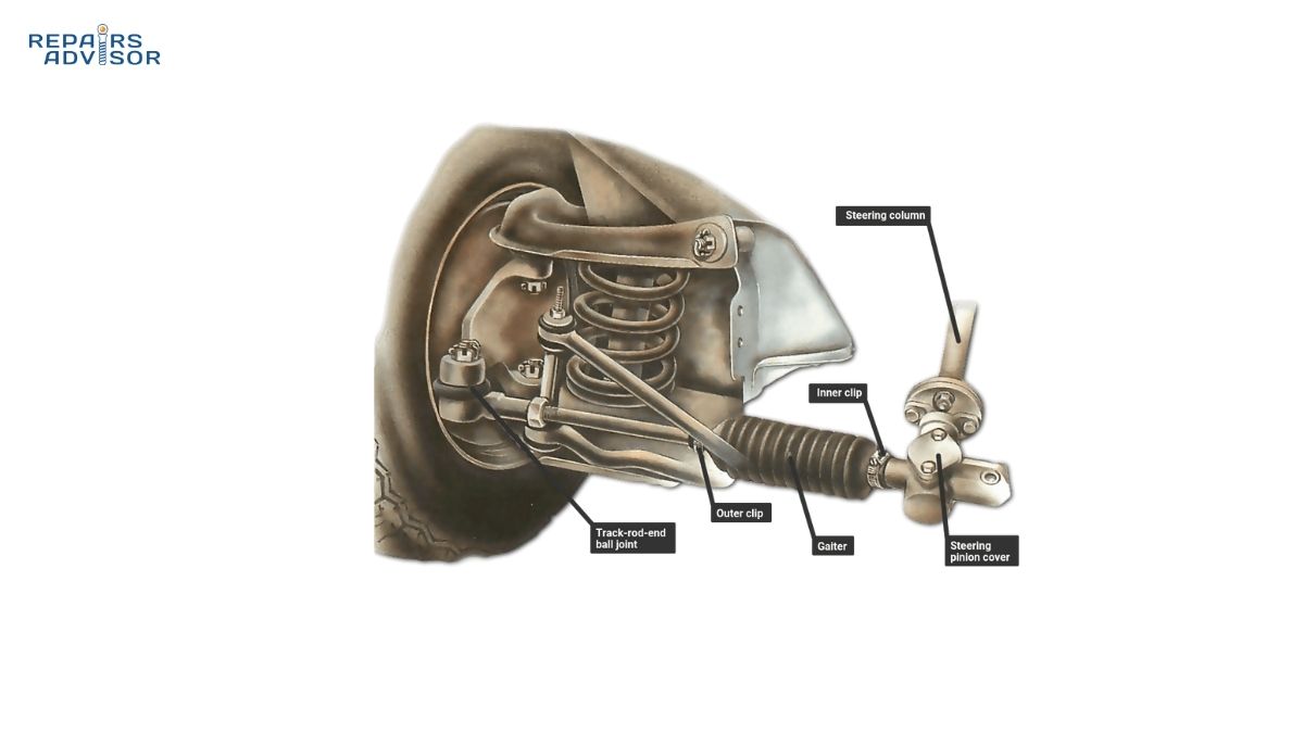
The relationship between toe and tire wear is both immediate and severe. Even 1/8″ of toe misalignment causes the tire to scrub sideways against its direction of travel with every rotation. This constant scrubbing creates a distinctive feathering wear pattern where the tread blocks develop a serrated edge, smooth on one side and sharp on the other. You can feel this pattern by running your hand across the tread—the feathering creates a noticeable rough sensation in one direction. Beyond accelerating tread wear, excessive toe misalignment increases rolling resistance, measurably reducing fuel economy. The continuous lateral scrubbing also generates heat buildup in the tire, potentially affecting its structural integrity over time. Understanding how rack and pinion steering connects to the wheels helps explain why steering component wear affects toe settings.
Four-wheel alignment has become standard practice because rear toe angles significantly affect vehicle tracking and thrust angle. Many modern vehicles with independent rear suspension offer rear toe adjustment, typically aiming for zero toe or slight toe-in at the rear. The rear toe setting determines the thrust line—the direction the rear axle actually points relative to the vehicle centerline. The front wheels must then be aligned to this thrust line, not to the vehicle body, to ensure the steering wheel centers properly when driving straight. This relationship explains why vehicles sometimes develop steering wheel misalignment even when front-wheel toe is correctly set—the rear thrust angle may have changed.
Toe adjustment is the most DIY-accessible alignment parameter because it can be modified by changing the length of the tie rods that connect the steering rack to the wheels. The tie rod ends thread into the tie rod body, and rotating them changes the effective length, thus altering toe. However, proper toe adjustment requires equal changes on both sides to maintain steering wheel centering. Professional alignment equipment measures toe to 1/100° precision using laser or camera systems, far exceeding the accuracy achievable with string-and-tape methods. While DIY toe measurement is possible for verification purposes, the safety-critical nature of steering geometry makes professional service advisable for actual adjustments.
DIY Tip for Intermediate Mechanics: You can check toe at home using a straight edge and measuring tape, comparing distances between wheel rims at hub height front and rear. However, this method only verifies gross misalignment—professional equipment is required for the precision necessary to maximize tire life and ensure proper tracking.
Kingpin Inclination and Steering Axis Inclination
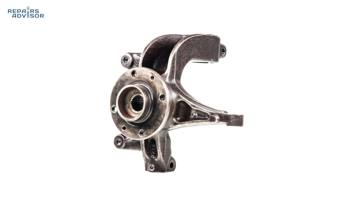
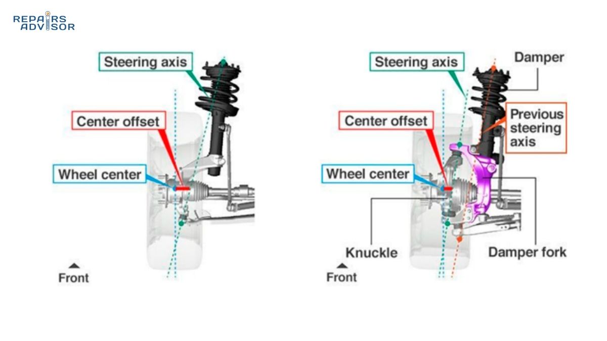
Kingpin Inclination (KPI), also called Steering Axis Inclination (SAI), describes the inward tilt of the steering axis when viewed from the front of the vehicle. The name “kingpin” is historical, referring to the physical pivot pin used in early solid-axle steering designs. Modern vehicles use ball joints or strut bearings instead of physical kingpins, but the term persists to describe the virtual line around which the wheel steers. On a MacPherson strut suspension, this line runs from the strut’s upper mount through the center of the lower ball joint. On double wishbone designs, it connects the upper and lower ball joint centers. Typical KPI angles range from 6° to 16° depending on the suspension design, with most passenger vehicles falling between 7° and 10°.
KPI creates a self-centering effect similar to, but distinct from, caster. When you turn the steering wheel, the KPI angle causes the spindle and wheel assembly to move upward slightly, literally lifting the front corner of the vehicle. This lifting action works against the vehicle’s weight, which naturally seeks the lowest position. The straight-ahead position represents this lowest point, so the vehicle’s weight constantly pushes the wheels back toward center. This weight-induced centering force supplements the centering effect created by caster angle, reducing the amount of positive caster required to achieve good straight-line stability. In fact, vehicles with higher KPI angles can use somewhat lower caster angles while maintaining excellent directional control.
The interaction between KPI and camber creates what alignment technicians call the included angle—simply the sum of the KPI angle and the camber angle (with negative camber treated as a negative number). While individual camber settings might differ slightly from left to right within acceptable tolerances, the included angle must be equal on both sides. This relationship provides powerful diagnostic information. If a vehicle shows equal camber on both sides but different included angles, one side must have different KPI—and since KPI is designed into the suspension geometry and not adjustable, this difference indicates a bent component. Specifically, an included angle variation typically means a bent steering knuckle, strut housing, or control arm. Understanding the relationship between KPI and steering knuckle design helps explain why this component is so critical to alignment.
Scrub radius represents another critical dimension related to KPI. This is the distance between where the steering axis (defined by the KPI angle) intersects the ground and where the tire’s centerline meets the ground. Positive scrub radius means the steering axis intersects the ground inside the tire’s contact patch—common on older vehicle designs. Zero scrub radius means the steering axis passes through the center of the tire’s contact patch. Negative scrub radius, where the steering axis intersects outside the tire contact patch, is standard on modern vehicles equipped with anti-lock braking systems.
Negative scrub radius provides important safety benefits during asymmetric braking events. If one front brake fails or loses pressure, or if you encounter a split-coefficient surface (one side on ice, the other on dry pavement), the differential braking forces create a strong pull toward one side. With negative scrub radius, this pull is partially self-correcting—the geometry helps stabilize the vehicle rather than amplifying the pulling force. This characteristic became particularly important with the advent of ABS systems, which can create rapid variations in individual wheel braking forces. The tradeoff is slightly increased steering effort, though modern power steering systems easily compensate.
Wheel offset changes directly affect scrub radius. Installing wheels with different offset than the original specification moves the tire contact patch laterally while the KPI angle remains fixed by the suspension geometry. This offset change alters scrub radius, potentially compromising the carefully engineered steering characteristics and stability built into the original design. Significant scrub radius changes can increase steering effort, create unusual torque steer characteristics, and affect how the vehicle responds to braking on varied surfaces. Understanding how double wishbone suspension geometry defines KPI angles helps explain why suspension design so profoundly affects steering characteristics.
Critical Professional Note: KPI angles are designed into the suspension geometry and are not adjustable in service. Any KPI measurement that falls outside manufacturer specifications absolutely indicates bent components—a situation that cannot be “aligned away” but requires parts replacement. Never accept alignment results that show out-of-specification KPI without addressing the underlying damage.
Ackermann Steering Geometry
The Ackermann principle solves a fundamental geometric challenge in vehicle steering. When a vehicle negotiates a turn, the inside wheels travel a shorter radius than the outside wheels—they’re tracing concentric circles with different diameters around a common center point. If both front wheels turned through identical angles during a turn, they would attempt to follow different-radius arcs while mechanically linked together, resulting in tire scrubbing, binding in the steering mechanism, and accelerated tire wear. The elegant solution, invented by German carriage builder Georg Lankensperger in 1816 and patented by his English agent Rudolph Ackermann in 1818, is to arrange the steering linkage so the inside wheel automatically turns through a greater angle than the outside wheel.
Before Ackermann geometry, horse-drawn carriages used turntable steering—a single pivot point under the wagon where the entire front axle rotated. This system was simple but created significant problems. The axle required substantial fore-and-aft travel space, limiting cargo area, and the long moment arm between the pivot and wheels amplified every road irregularity, creating harsh impacts through the steering. Ackermann’s innovation separated steering into two pivot points, one near each front wheel hub, dramatically improving both packaging and control. The system’s brilliance lies in its purely geometric solution requiring no complex mechanisms or adjustments—the angles are built into the fixed relationship between components.
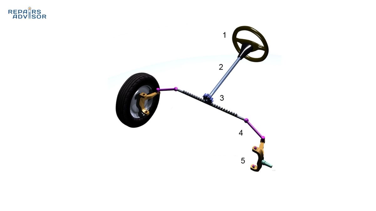
The key to Ackermann geometry is angling the steering arms toward a point on or near the rear axle centerline. When the tie rod connects these angled steering arms, the resulting trapezoid shape means the linkage deforms differently on each side as you turn the steering wheel. Picture a trapezoid with the narrow end forward: as this shape is pushed sideways, the leading corners (where the steering arms attach to the wheels) move through different angular distances. The inside wheel, which needs to turn more sharply, rotates through a greater angle because its steering arm follows a more acute geometric path. The relationship between wheelbase (distance between front and rear axles) and track width (distance between left and right wheels) determines the specific angles required for this geometry. Understanding how rack and pinion geometry creates this effect helps visualize the mechanical implementation.
Perfect Ackermann geometry would arrange the steering linkage so that, at any steering angle, all four wheels turn around a common instantaneous center of rotation. The geometric center point lies on a line extending from the rear axle, with the front wheel steering axes all intersecting at this point. In practice, achieving perfect Ackermann across the entire steering range is impossible because the linkage traces complex arcs as it moves. Modern passenger cars typically employ 20-40% Ackermann—a compromise that provides good low-speed maneuverability while accounting for real-world dynamic considerations.
The dynamic complications involve tire slip angles—the difference between where a pneumatic tire points and where it actually travels under cornering forces. When a vehicle corners at speed, the tires deform laterally, creating slip angles that vary with the load on each tire. During cornering, weight transfers to the outside wheels, increasing their load while reducing load on the inside wheels. Each tire has an optimum slip angle for maximum lateral force generation, but this optimum angle changes with load. At higher speeds, the loaded outside front tire might need to operate at a larger slip angle than the lightly loaded inside tire. This dynamic requirement is exactly opposite to what geometric Ackermann provides—pure Ackermann increases the inside wheel angle, not the outside wheel angle.
This contradiction explains why different vehicle types use varying amounts of Ackermann. Economy sedans and family vehicles prioritize low-speed maneuverability and parking convenience, specifying more Ackermann geometry. Sports cars and performance vehicles, which spend more time at higher speeds where tire slip angles dominate, trend toward parallel steer (0% Ackermann) or even slight anti-Ackermann (where the outside wheel turns more than the inside). Racing applications take this further, with some race cars using significant anti-Ackermann, accepting the resulting low-speed tire scrubbing in exchange for optimized high-speed cornering balance. Drift cars represent a special case, modified for extreme steering angles often exceeding 60° where standard Ackermann geometry becomes irrelevant to the sliding technique.
Aerodynamic considerations also influence Ackermann selection in modern high-performance vehicles. The angle of the inside front wheel during high-speed cornering can affect airflow to critical cooling components or aerodynamic devices. In some cases, additional Ackermann is specified not for tire reasons but to angle the inside wheel to manage airflow more effectively. The complexity of these interactions—tire dynamics, weight transfer, aerodynamics, and pure geometry—explains why no single “correct” Ackermann percentage exists. Each vehicle represents a carefully balanced compromise optimized for its intended use.
Engineering Note for Advanced Enthusiasts: The mathematical relationship for perfect Ackermann can be expressed as: cot(δᵢ) – cot(δₒ) = t/L, where δᵢ and δₒ are the inside and outside wheel angles, t is the track width, and L is the wheelbase. This equation shows how wheelbase and track fundamentally determine the geometric requirement, though real implementations deviate from this ideal for the dynamic reasons discussed.
Four-Wheel Alignment Concepts
Modern alignment service has evolved beyond simply setting front wheel angles. Four-wheel alignment recognizes that the rear axle orientation fundamentally affects how the vehicle tracks and where the steering wheel centers. The rear wheels, whether on a solid axle or independent suspension, define a thrust line—the direction the rear axle actually points relative to the vehicle’s geometric centerline. This thrust line, not the vehicle body centerline, becomes the reference for aligning the front wheels. Think of it this way: the rear axle determines where the vehicle is actually going, so the front wheels must be aligned to that direction for the steering wheel to center properly.
Thrust angle measures the difference between the rear axle thrust line and the vehicle geometric centerline, typically expressed in degrees or decimal degrees. A vehicle with zero thrust angle has the rear wheels pointing exactly in the same direction as the geometric centerline—an ideal situation. Most manufacturers specify acceptable thrust angles of less than 0.2°, though some sources allow up to 0.5° depending on the vehicle. Thrust angles exceeding these tolerances create a condition called dog-tracking, where the vehicle appears to move slightly sideways as it travels forward, with the rear end offset from the path traced by the front wheels.
The symptoms of excessive thrust angle are distinctive. Your steering wheel will be off-center when driving straight, pulled to one side to compensate for the rear axle pointing in a different direction. The vehicle may track straight, but you’re holding the wheel at an angle to achieve this straight tracking. This situation differs from a pull, where the vehicle actively steers toward one side when you release the wheel. With thrust angle problems, the vehicle goes straight—just not with the steering wheel centered. Correcting thrust angle requires rear wheel toe adjustment on vehicles with independent rear suspension, or checking for bent axle components on solid rear axle designs.
Setback describes a front-to-rear position difference between the left and right wheels on the same axle. Imagine looking down on your vehicle from above: setback means one front wheel is slightly ahead of the other front wheel, or one rear wheel leads its opposite-side partner. Setback is measured in inches or millimeters, with most manufacturers specifying less than 1/4″ acceptable difference. Like thrust angle, setback doesn’t directly cause handling problems in most situations, but significant setback indicates underlying issues—bent frame rails, impact damage, or worn suspension bushings that have allowed components to shift position.
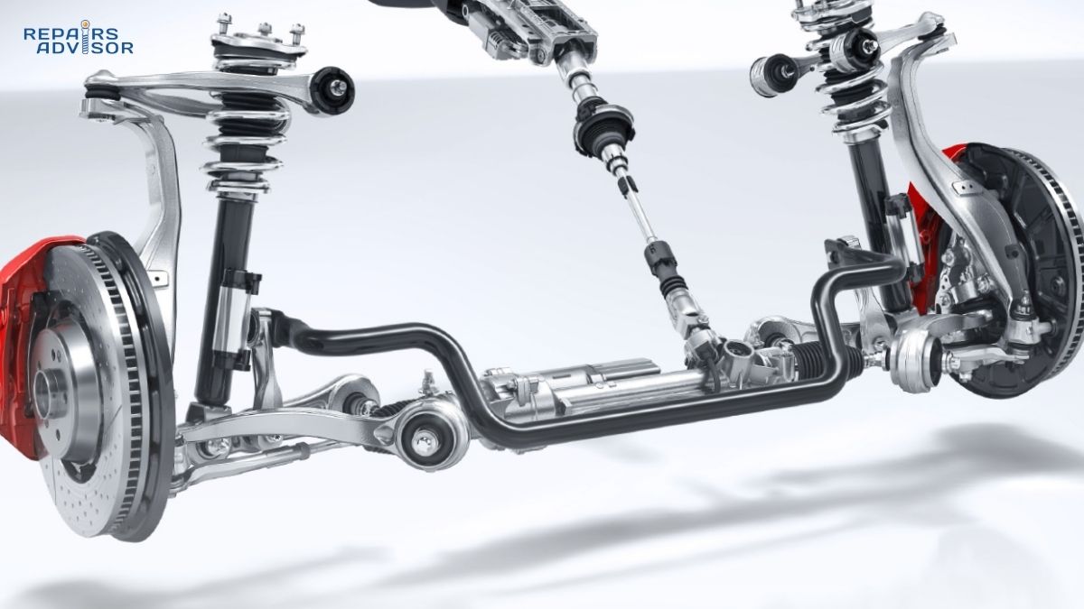
Many modern vehicles feature independent rear suspension with adjustable toe settings, making comprehensive four-wheel alignment essential. The rear toe adjustment allows technicians to correct thrust angle, ensuring the rear axle points straight before aligning the front wheels to this corrected thrust line. Vehicles with solid rear axles can’t adjust rear toe, but the thrust angle must still be measured. If a solid rear axle shows excessive thrust angle, it indicates bent axle housing or suspension mounting points—problems requiring parts replacement rather than adjustment. Understanding how your complete suspension system works together helps appreciate why all four wheels must be considered during alignment service.
The alignment sequence matters significantly. Professional technicians always begin with the rear axle, measuring and adjusting rear toe (if adjustable) to correct thrust angle first. Only after establishing the proper rear thrust line do they adjust the front wheels to align with this reference. This sequence ensures that both the front wheels and steering wheel are properly centered relative to where the vehicle actually tracks. Attempting to align the front wheels first, without addressing rear axle issues, might center the steering wheel but would leave the vehicle with built-in steering compensation for a crooked rear axle—a fundamentally flawed approach.
Professional Service Note: Four-wheel alignment is not optional on modern vehicles with independent rear suspension—it’s mandatory for proper handling and steering wheel centering. Even vehicles with solid rear axles benefit from four-wheel measurement to identify damage or wear that might not be obvious through visual inspection. The modest additional cost over front-only alignment delivers significant value in driving quality and tire longevity.
Steering Geometry Location and Service Access
The angles that define steering geometry originate from the precise three-dimensional positioning of suspension and steering components. Understanding where these geometric relationships are created helps explain why some adjustments are possible while others require parts replacement. The foundation begins with the vehicle’s frame or unibody structure—every suspension mounting point, strut tower, and subframe attachment creates reference points that define the suspension geometry. Deformation in these structural elements, whether from collision damage or rust-induced deterioration, can alter geometry in ways that exceed the normal adjustment range.
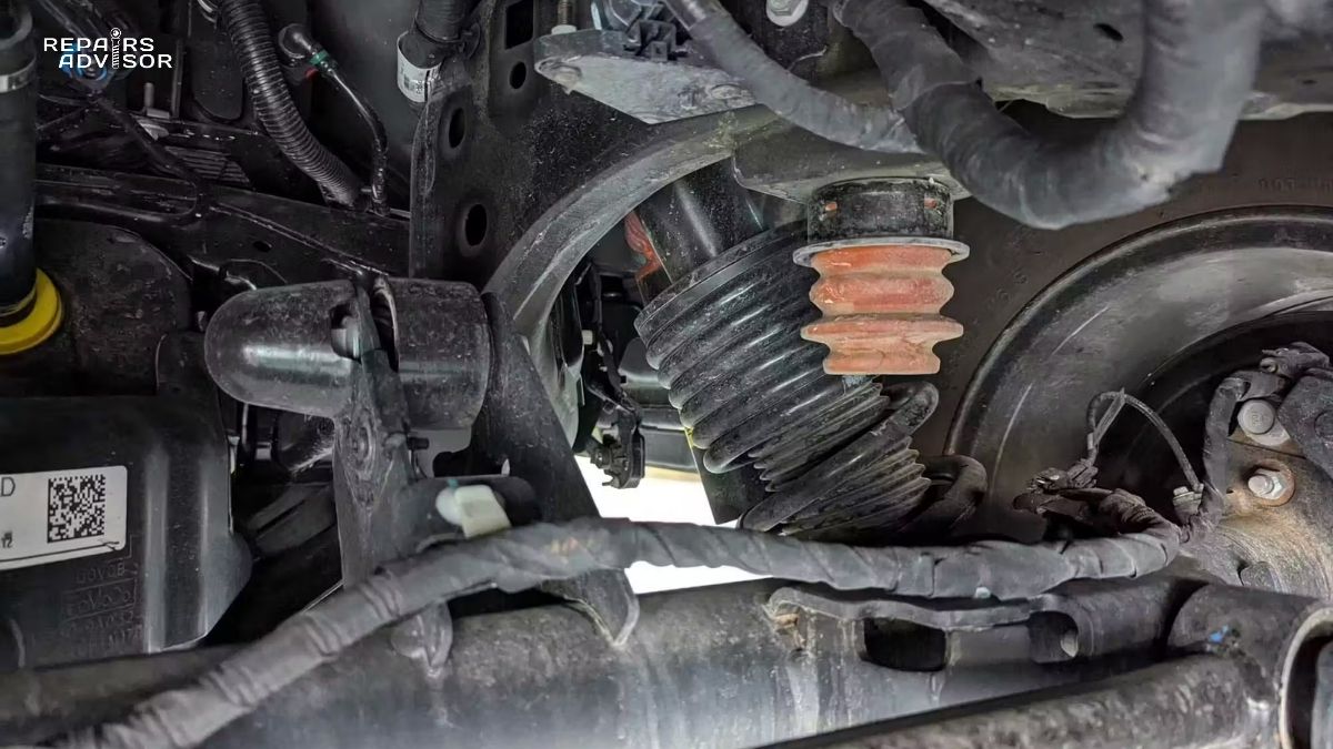
On MacPherson strut suspensions, the upper strut mount bolted to the strut tower defines the top of the steering axis, while the lower ball joint or hub carrier mounting establishes the lower point. The linear distance between these points, their angular relationship to vertical (viewed from front for KPI, from side for caster), and how the steering knuckle positions the wheel hub relative to this axis all contribute to the overall geometry. Control arm mounting locations, bushing compliance characteristics, and stabilizer bar end link positions further influence how the suspension behaves dynamically. Even the placement of the steering rack and the specific attachment points for tie rods affect Ackermann characteristics and how steering input translates to wheel angle.
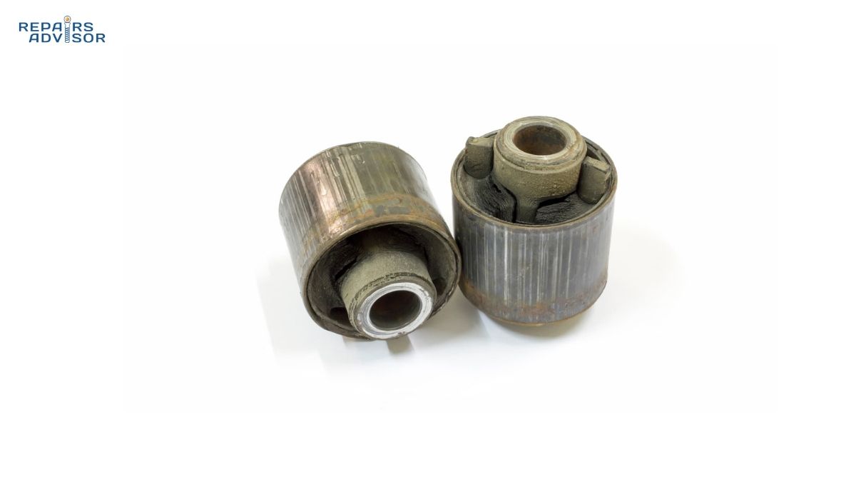
Adjustment capabilities vary dramatically between vehicle designs. Front wheel toe remains universally adjustable through tie rod length changes, making it the most accessible alignment parameter. Front camber adjustment is common but not universal—many vehicles provide slotted holes, eccentric bolts, or other adjustment methods, while economy models often include no provision for camber changes. Caster adjustment is frequently limited or impossible on modern unibody vehicles, with the caster angle determined by fixed suspension mounting points. Rear alignment adjustability has increased significantly in recent years as independent rear suspension has become standard, with many vehicles now offering both rear toe and rear camber adjustment. Understanding how control arm bushings affect suspension geometry helps explain why worn bushings prevent accurate alignment.
Professional alignment equipment represents a substantial investment in precision measurement capability. A full four-wheel alignment rack includes a perfectly level surface with rolling and turning plates that allow the wheels to move freely while measurements are taken. Each wheel receives a sensor—either a mechanical attachment or an optical target—that communicates the wheel’s spatial orientation to a central computer. Modern systems achieve measurement accuracy of ±0.01° or better, using either laser-based distance measurement or high-resolution camera systems that read optical patterns on the wheel sensors. The computer database contains manufacturer specifications for thousands of vehicle configurations, accounting for differences in options, trim levels, and equipment that affect alignment requirements.
The alignment process follows strict procedures to ensure accuracy. Technicians begin with a pre-alignment inspection, checking tire pressure (crucial for accurate measurements), tire condition, and suspension component wear. All play must be eliminated from ball joints, tie rod ends, and wheel bearings before attempting alignment, as looseness prevents maintaining accurate settings. The vehicle undergoes a specific settling procedure—typically pushing down on each corner to compress and release the suspension several times—that eliminates friction in the suspension system and allows components to find their natural position. Ride height is verified against specifications, as incorrect ride height (from worn springs or modified suspension) affects all alignment angles.
Measurement begins with the rear axle, establishing thrust angle and making any rear toe or camber adjustments required by specifications. Front wheel measurements follow, with adjustments made in a specific sequence: caster first (if adjustable), then camber, then toe. This sequence exists because caster adjustments affect camber readings, and both caster and camber adjustments affect toe. Making adjustments in the wrong order would require multiple iterations to achieve all angles simultaneously within specification. After adjustments, a road test verifies that the vehicle tracks straight, the steering wheel is centered, and no pulling or handling abnormalities exist.
The critical question for DIY mechanics involves identifying the boundary between what’s reasonably accomplished at home versus what demands professional service. Visual inspection for obvious damage—bent control arms, leaking shock absorbers, torn ball joint boots—falls well within DIY capability. Basic toe measurement using a straight edge and measuring tape can identify gross misalignment, though the accuracy limitations prevent optimizing tire life. However, the actual adjustment of any alignment angle beyond basic toe changes enters territory where professional equipment becomes essential. The precision required for proper geometry—fractions of a degree—exceeds what’s achievable with improvised tools. More critically, alignment directly affects vehicle control and braking stability, making it a safety-critical system where professional expertise provides important peace of mind.
Safety Warning for All Skill Levels: Steering geometry directly affects how your vehicle responds during normal driving, emergency maneuvers, and braking events. While inspection for damage is DIY-appropriate, the precision required for proper alignment and the safety implications of incorrect settings make professional service mandatory. The cost of professional four-wheel alignment, typically $75-150, represents sound investment in both safety and tire longevity compared to the risk of improper DIY adjustment.
Alignment Service and Maintenance
Recognizing when your vehicle needs alignment service involves observing specific symptoms and following preventive maintenance schedules. The most obvious indicator is a steering wheel that’s off-center when driving straight on a level road. This symptom specifically suggests toe misalignment or rear thrust angle problems. Vehicle pulling—where the car actively steers to one side when you release the wheel—can indicate camber differences, caster differences, or non-alignment issues like uneven tire pressure or brake drag. Uneven tire wear patterns provide definitive evidence of alignment problems: one-sided wear indicates camber issues, feathering suggests toe problems, and center wear combined with pulling might point to caster.
Beyond responding to symptoms, proactive alignment service following a logical maintenance schedule prevents many problems. Annual alignment checks, or every 12,000-15,000 miles, catch gradual changes from normal component wear before they create tire damage. Mandatory alignment occasions include any suspension component replacement—installing new struts, control arms, ball joints, or steering components changes the precise geometry relationships and requires verification. Tire replacement presents an excellent opportunity for alignment service, as you’re already paying for tire mounting and balancing. Catching alignment problems before mounting new tires prevents immediately destroying fresh rubber. Any significant impact event—striking a curb, hitting a deep pothole, or being involved in even a minor collision—warrants immediate alignment inspection, as these impacts can bend components without creating obvious visual damage.
Professional alignment service encompasses far more than simply adjusting toe settings. The service begins with comprehensive pre-alignment inspection, examining tire pressure, tire condition for unusual wear patterns, and systematic checking of all suspension and steering components for wear or damage. Ball joint play, tie rod end looseness, control arm bushing deterioration, wheel bearing play—any excessive movement in these components must be corrected before alignment attempt. Attempting to align a vehicle with worn components wastes money, as the loose parts prevent maintaining the adjusted settings. This inspection often reveals necessary repairs, and addressing them before alignment saves repeating the service after parts replacement.
After confirming mechanical soundness, the technician performs the settling procedure—loading and releasing each corner of the suspension multiple times—that overcomes static friction in bushings and allows the suspension to find its natural position. Ride height verification compares actual measurements against specifications, as worn springs or modified suspension alter geometry in ways that affect alignment angle requirements. The vehicle then undergoes complete measurement of all wheels, with results compared against manufacturer specifications and tolerance ranges.
Adjustment procedures follow the established rear-first, caster-camber-toe sequence that accounts for how changes in one angle affect others. Modern alignment machines display live angle readings, allowing technicians to observe how adjustments change measurements in real-time. The goal is to position all adjustable angles within the preferred range—typically the middle third of the acceptable specification window—rather than just barely meeting minimum requirements. Cross-vehicle comparisons (left versus right) receive particular attention, as excessive side-to-side differences cause pulling even when both sides fall within individual specifications. Understanding how shock absorbers and struts affect suspension geometry helps explain why worn dampers should be replaced before alignment service.
Alignment specifications themselves vary significantly by vehicle make, model, year, and sometimes even trim level or option packages. Manufacturers determine these specifications through extensive testing, balancing handling characteristics, tire wear, and ride comfort for each specific vehicle configuration. Tolerance ranges typically include a preferred setting (the target value), acceptable minimum, and acceptable maximum. Quality alignment service aims for the preferred specification rather than just getting within the tolerance window. Some vehicles specify different settings for laden versus unladen conditions, accounting for how passenger and cargo weight affect suspension position and, consequently, alignment angles.
Common alignment problems often indicate specific underlying failures. When measurements show all specifications out of tolerance by similar amounts, the likely cause is ride height problems from worn springs or modified suspension. When one wheel shows drastically different angles than its opposite-side partner, bent components are indicated—frame damage, bent control arms, or damaged strut housings. When angles change significantly between measurements, worn bushings or loose fasteners prevent stable geometry. Professional technicians recognize these patterns, using alignment readings as diagnostic information that guides repair recommendations. Simply adjusting angles without addressing underlying mechanical problems provides only temporary relief before the geometry drifts out of specification again.
The value proposition of professional alignment service becomes clear when comparing costs. Professional four-wheel alignment typically ranges from $75-150 depending on location and vehicle complexity. This service, properly performed, optimizes tire life and ensures safe vehicle control. The alternative—neglecting alignment until tire wear forces replacement—costs $400-800 for a set of four quality tires, along with the safety compromise of operating with poor handling characteristics. Tire manufacturers generally state that proper alignment throughout a tire’s life contributes approximately 25% to its longevity. From this perspective, alignment service represents insurance against premature tire replacement, returning its cost multiple times over through extended tire life.
Professional Consultation Recommendation: Any time you experience handling changes, observe unusual tire wear, replace suspension or steering components, or experience impact damage, professional alignment service should follow immediately. The modest cost provides both safety assurance and economic benefit through maximized tire life. If your vehicle is more than a year or 15,000 miles from its last alignment service, schedule preventive maintenance before problems develop.
Conclusion
Steering geometry represents one of the most precisely engineered systems on your vehicle, with five fundamental angles—camber, caster, toe, kingpin inclination, and scrub radius—working in concert to provide predictable handling, maximize tire life, and ensure safe vehicle control. The camber angle determines tire contact patch optimization during straight-line driving and cornering. Caster creates the self-centering force that provides steering feel and high-speed stability. Toe, the most critical angle for tire wear, must be precisely maintained to prevent the costly feathering that rapidly destroys tire tread. Kingpin inclination contributes additional self-centering force while defining scrub radius characteristics that affect steering effort and stability during braking events.
Beyond these individual angles, Ackermann steering geometry solves the fundamental challenge of allowing inside and outside wheels to trace different-radius paths during turns without tire scrubbing or steering bind. The elegant geometric solution, invented over 200 years ago, remains the foundation of modern steering systems, though contemporary implementations balance pure Ackermann geometry against dynamic tire behavior at higher speeds. The percentage of Ackermann built into each vehicle’s steering represents a carefully optimized compromise between low-speed maneuverability and high-speed cornering performance, tailored to the vehicle’s intended use.
Four-wheel alignment has evolved from an optional service to a mandatory procedure on modern vehicles. The rear axle thrust angle fundamentally affects where the vehicle tracks and where the steering wheel centers, making rear measurement and adjustment essential for proper front wheel alignment. Even vehicles with non-adjustable solid rear axles benefit from thrust angle measurement that identifies damage or wear requiring attention. The alignment sequence—rear adjustment first, followed by front caster, camber, and finally toe—ensures all angles achieve proper specification simultaneously.
The precision required for proper alignment—measurements accurate to hundredths of a degree—exceeds what any DIY approach can achieve without specialized equipment costing thousands of dollars. While inspection for obvious damage and basic toe verification remain appropriate for skilled DIY mechanics, the actual adjustment of alignment angles falls firmly in professional service territory. The safety implications of improper geometry—compromised vehicle control during emergency maneuvers or braking events—make professional expertise essential. Professional alignment service, typically $75-150, represents sound investment when compared to the $400-800 cost of premature tire replacement and the immeasurable value of safe, predictable vehicle behavior.
Regular alignment maintenance, whether annual or every 12,000-15,000 miles, catches gradual changes before they create tire damage. Mandatory alignment occasions include any suspension component replacement, tire installation, or impact event. The comprehensive pre-alignment inspection often reveals worn components requiring replacement before alignment can be properly set and maintained. This diagnostic value adds to the service’s worth, identifying problems before they progress to failure.
Understanding steering geometry transforms from academic knowledge to practical benefit when you recognize alignment symptoms early and pursue professional service before expensive consequences develop. Your vehicle’s handling characteristics, tire longevity, and fundamental safety all depend on maintaining proper geometric relationships between suspension, steering, and wheels. These angles aren’t optional settings subject to casual tolerance—they’re precisely engineered specifications that, when maintained, deliver the driving experience and safety performance the manufacturer intended.
Final Safety Reminder: Steering geometry directly affects vehicle control during normal driving, emergency maneuvers, and braking. Professional alignment service using calibrated equipment is mandatory for safety after suspension work, impact damage, or when symptoms indicate geometry problems. The modest investment in professional service prevents catastrophic tire wear and ensures your vehicle responds predictably when it matters most.
Next Steps: For detailed repair manual guidance including complete alignment specifications for your specific year, make, and model, along with diagnostic procedures for suspension component inspection, explore the comprehensive repair manual collection at Repairs Advisor. Professional repair information helps you communicate effectively with service providers and understand the work your vehicle requires.