Modern engines rely on sophisticated intake air control devices to optimize combustion efficiency, reduce emissions, and maximize performance across all operating conditions. These advanced systems create controlled air motion patterns within the combustion chamber, directly impacting fuel mixing, flame propagation, and overall engine performance. Understanding how tumble flaps, swirl valves, and variable intake runners work together provides essential insight into contemporary engine management technology.
Professional mechanics leverage this knowledge for diagnostic efficiency, while DIY enthusiasts can better understand performance modifications and maintenance requirements. Beginners should focus on recognizing these systems during routine maintenance, always consulting professional guidance for any modifications or repairs involving intake air control devices.
Why Intake Air Control Devices Are Critical for Engine Performance
Intake air control devices serve as the sophisticated orchestrators of combustion chamber airflow, creating precisely controlled turbulence patterns that enhance fuel-air mixing and combustion efficiency. These systems generate two primary air motion patterns: tumble (vertical air rotation) and swirl (horizontal air rotation), each optimized for different engine operating conditions and combustion chamber designs.
The primary function centers on optimizing the air-fuel mixture formation through controlled turbulence generation. Tumble flaps create vertical air motion that enhances mixing during the compression stroke, particularly beneficial at part-throttle conditions where fuel atomization requires additional energy. Swirl valves generate horizontal air motion that maintains flame front propagation consistency, especially important in diesel engines and direct-injection gasoline applications.
ECU control systems continuously monitor engine load, speed, and temperature conditions to determine optimal air motion patterns. During cold start conditions, increased tumble motion helps compensate for poor fuel vaporization, while high-load conditions may require reduced air motion to minimize pumping losses. This dynamic adjustment capability represents a significant advancement over fixed intake runner designs.
For professional mechanics, understanding these systems is crucial when diagnosing performance issues, particularly those involving irregular idle, combustion knock, or emissions compliance failures. How Engine Management Systems Work provides comprehensive coverage of the electronic control integration that manages these devices.
Intermediate DIY enthusiasts should recognize that intake air control device problems often manifest as performance inconsistencies rather than complete failure, making systematic diagnosis essential. Common symptoms include rough idle, reduced fuel economy, or check engine lights related to air-fuel mixture control.
Safety Note for All Skill Levels: Intake air control devices operate under vacuum and electronic control. Any diagnostic or repair work should include proper safety procedures, including battery disconnection and verification of no stored energy in electronic actuators before component removal.
Intake Air Control Device Parts and Construction Explained
The construction of intake air control devices involves precisely engineered components designed to create controlled airflow disturbances while maintaining optimal flow characteristics across all operating conditions. Understanding the mechanical and electronic integration reveals the sophistication of modern engine management systems.
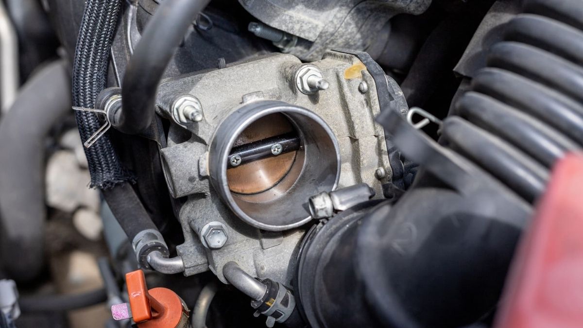
Tumble flap assemblies consist of butterfly-style valves mounted on shafts within the intake runners, typically positioned close to the intake ports for maximum effectiveness. The flap design incorporates aerodynamic profiling to minimize pressure drop when fully open while creating maximum turbulence when partially closed. Professional mechanics recognize that tumble flap shaft wear and actuator failures are common service issues, particularly in higher-mileage vehicles.
The actuator systems utilize either vacuum-operated diaphragms or electronic stepper motors, depending on manufacturer design philosophy and cost considerations. Vacuum-operated systems integrate with the engine management vacuum network, while electronic systems offer more precise control but require additional wiring and electronic feedback systems.
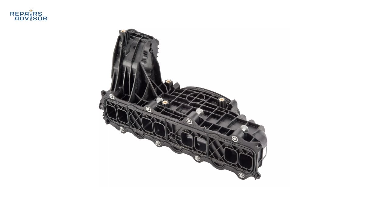
Swirl valve construction varies significantly between manufacturers, with some utilizing rotating drums within the intake manifold and others employing sliding plates or rotating vanes. The BMW swirl flap system represents one of the most complex implementations, incorporating multiple individually controlled valves per cylinder.
Variable intake runner systems extend the concept further, incorporating adjustable runner lengths or cross-sectional areas to optimize airflow characteristics across the entire RPM range. These systems typically combine mechanical complexity with sophisticated electronic control, requiring specialized diagnostic equipment for proper service.
The ECU control integration involves multiple sensor inputs including manifold absolute pressure, engine speed, coolant temperature, and throttle position. How Throttle Position Sensors Work explains the critical sensor integration that enables precise air motion control.
Construction materials must withstand continuous temperature cycling, vacuum exposure, and potential carbon buildup from crankcase ventilation systems. Aluminum and engineered plastics dominate modern designs, with sealed bearings and corrosion-resistant coatings extending service life.
For DIY enthusiasts, visual inspection during routine maintenance can identify obvious problems such as seized actuators, damaged linkages, or excessive carbon buildup. However, complete diagnosis requires specialized scan tools capable of commanding actuator operation and monitoring system response.
Maintenance consideration: These systems benefit from quality fuel and regular air filter maintenance, as contamination accelerates wear and can cause binding in precision-fitted components.
How Intake Air Control Devices Work: Step-by-Step Operation
The operation of intake air control devices represents a sophisticated integration of mechanical engineering and electronic control, continuously adapting air motion characteristics to match engine operating conditions and performance requirements. This step-by-step analysis reveals the complex coordination required for optimal combustion enhancement.
Step 1: ECU Condition Assessment
The engine control unit continuously monitors engine operating parameters including RPM, load, coolant temperature, and throttle position. During cold start conditions, the ECU commands increased tumble motion to enhance fuel vaporization and mixing. At idle, controlled swirl motion maintains combustion stability while minimizing pumping losses.
Step 2: Control Signal Generation
Based on the monitored conditions, the ECU generates control signals to the intake air control actuators. Vacuum-operated systems receive duty-cycle controlled vacuum signals through solenoid valves, while electronic systems receive direct PWM or stepper motor commands. How Engine Management Systems Work details the comprehensive sensor network that enables this precise control.
Step 3: Mechanical Actuation
The actuator systems respond to ECU commands by positioning the tumble flaps or swirl valves to create the desired air motion patterns. Tumble flap systems typically operate in synchronized groups, while more sophisticated systems allow individual cylinder control for optimized performance balancing.
Step 4: Airflow Pattern Generation
As intake air passes through the controlled restrictions created by the positioned valves, it develops the intended motion patterns. Tumble motion creates vertical air rotation that enhances mixing during compression, while swirl motion generates horizontal rotation that maintains flame front consistency during combustion.
Step 5: Combustion Enhancement
The controlled air motion directly impacts fuel-air mixing quality, flame propagation speed, and combustion completeness. During part-throttle operation, enhanced mixing compensates for reduced air velocity, while high-load operation may minimize air motion to reduce pumping losses and maximize volumetric efficiency.
Step 6: Feedback and Adaptation
Advanced systems incorporate feedback sensors to monitor actual air motion or combustion quality. Pressure sensors in the intake manifold provide indirect feedback, while knock sensors indicate combustion quality. The ECU uses this feedback to refine control algorithms and compensate for component wear over time.
Professional diagnostic insight: System operation can be verified using scan tools capable of commanding actuator operation while monitoring intake manifold vacuum patterns. Irregularities in vacuum response often indicate mechanical problems with the actuator or valve assemblies.
For DIY diagnosis: Simple tests include listening for actuator operation during engine start-up and monitoring engine performance for irregularities that might indicate air motion control problems. However, comprehensive diagnosis requires professional-level equipment and expertise.
Integration with related systems: Intake air control device operation coordinates with variable valve timing systems and direct injection timing to optimize overall combustion efficiency.
Performance impact: Properly functioning intake air control devices can improve fuel economy by 3-8% while reducing emissions and enhancing drivability across all operating conditions.
Intake Air Control Device Location and Access Guide
Locating and accessing intake air control devices requires systematic understanding of engine layout and component integration, as these systems are typically integrated within the intake manifold assembly or positioned between the throttle body and cylinder head. Proper access techniques ensure safe and effective maintenance or diagnostic procedures.
Primary location identification begins with the intake manifold assembly, where most tumble flaps and swirl valves are integrated directly into the runner design. Professional mechanics recognize that access often requires partial or complete intake manifold removal, particularly on V-configuration engines where space constraints limit component accessibility.
Tumble flap systems are commonly located within individual intake runners, positioned close to the intake ports for maximum air motion effectiveness. On inline engines, access may be possible from above with throttle body removal, while V-configuration engines often require additional component removal including intake plenum sections or fuel rail assemblies.
Actuator location varies significantly between manufacturers, with some systems utilizing centrally mounted actuators connected through linkage assemblies, while others incorporate individual actuators for each valve assembly. Mercedes-Benz intake systems often feature complex multi-actuator designs requiring specialized removal procedures.
Access considerations for DIY enthusiasts should focus on visual inspection opportunities during routine maintenance. Many systems allow limited inspection through throttle body removal, though complete access requires professional-level disassembly procedures and specialized tools.
Safety requirements for accessing intake air control devices include proper battery disconnection to prevent accidental actuator operation during service. Additionally, intake manifold work requires attention to fuel system depressurization procedures and coolant handling on systems with integrated coolant passages.
Tool requirements typically include standard metric socket sets, specialized intake manifold removal tools, and scan tools for actuator positioning during assembly. Professional-level work may require manufacturer-specific alignment tools and calibration procedures following component replacement.
Component identification can be challenging due to integration with other intake systems. Tumble flaps may appear similar to traditional butterfly valves but incorporate specific aerodynamic profiling and linkage connections to actuator systems. How Intake Manifolds Work provides comprehensive coverage of intake system integration.
Inspection points during access include actuator operation verification, linkage condition assessment, and carbon buildup evaluation on valve surfaces. Carbon accumulation reduces effective opening area by up to 40%, creating measurable performance losses including rough idle (±50 RPM variation), reduced fuel economy (2-4% degradation), and increased emissions. Professional ultrasonic cleaning or chemical decarbonization procedures can restore full functionality and return system pressure drop characteristics to specification (2-4% fully open, 15-25% optimal restriction).
Reassembly considerations include proper torque specifications for intake manifold bolts, actuator calibration procedures, and system relearning through scan tool procedures. Many systems require specific initialization sequences following component replacement or major service.
Model-specific guidance: Access procedures vary significantly between manufacturers and model years. BMW intake systems, Audi intake designs, and Volkswagen applications each incorporate unique access requirements and service procedures.
Professional recommendation: Given the complexity and potential for expensive damage during disassembly, intake air control device service should typically be performed by qualified technicians with manufacturer-specific training and equipment. DIY enthusiasts should focus on external inspection and basic maintenance tasks while leaving major service to professionals.
Conclusion
Intake air control devices represent sophisticated engineering solutions that significantly impact engine performance, fuel economy, and emissions compliance. These systems demonstrate the evolution of engine management technology from simple mechanical designs to complex electromechanically controlled assemblies that continuously optimize combustion characteristics.
For professional mechanics, mastering intake air control device diagnosis and service represents essential skills in modern automotive repair, particularly as these systems become more prevalent across all manufacturer lines.
DIY enthusiasts benefit from understanding these systems to make informed maintenance decisions and recognize when professional service is required. Regular maintenance of related components including air filters and fuel system components supports long-term system reliability.
Beginning automotive enthusiasts should recognize intake air control devices as advanced systems requiring professional attention for major service, while focusing their DIY efforts on supporting systems and routine maintenance tasks.
Safety reminder: All work involving intake air control devices should include proper safety procedures, manufacturer-specific service information, and professional consultation when system complexity exceeds individual skill levels. These systems directly impact engine operation and emissions compliance, making proper service procedures essential for reliable operation.
Information provided for educational reference only. Always consult manufacturer service information and professional guidance for specific diagnostic and repair procedures. Intake air control device work may require specialized tools and training beyond typical DIY capabilities.