Why Ignition System Is Critical for Electrical Function
The ignition system serves as the foundation of engine electrical function, creating precisely timed spark events that initiate combustion in each cylinder. This sophisticated electrical network coordinates spark plugs, ignition coils, and timing control components to deliver high-voltage energy exactly when needed for optimal engine performance. Without proper ignition system operation, even perfectly functioning engines cannot start or run efficiently.
Modern ignition systems generate voltages exceeding 40,000 volts, transforming low-voltage battery power into the intense electrical energy required to jump spark plug gaps and ignite compressed air-fuel mixtures. The system’s timing precision directly impacts engine power output, fuel efficiency, and emissions compliance, making it critical for overall vehicle electrical function.
Quick Facts:
- Function: High-voltage spark generation and timing control
- Primary Components: Ignition coils, spark plugs, ignition module, crankshaft position sensor
- Voltage Range: 40,000-100,000 volts output
- Failure Impact: No-start conditions, misfiring, reduced performance, increased emissions
Safety Note: Ignition systems operate at extremely high voltages. Always disconnect the battery and follow manufacturer safety procedures before working on ignition components. Professional diagnosis is recommended for complex ignition system troubleshooting.
Ignition System Parts and Construction Explained
Modern automotive ignition systems integrate multiple precision components working in perfect synchronization. Understanding each component’s construction reveals how the system achieves reliable spark generation across all engine operating conditions.
Primary Components Overview
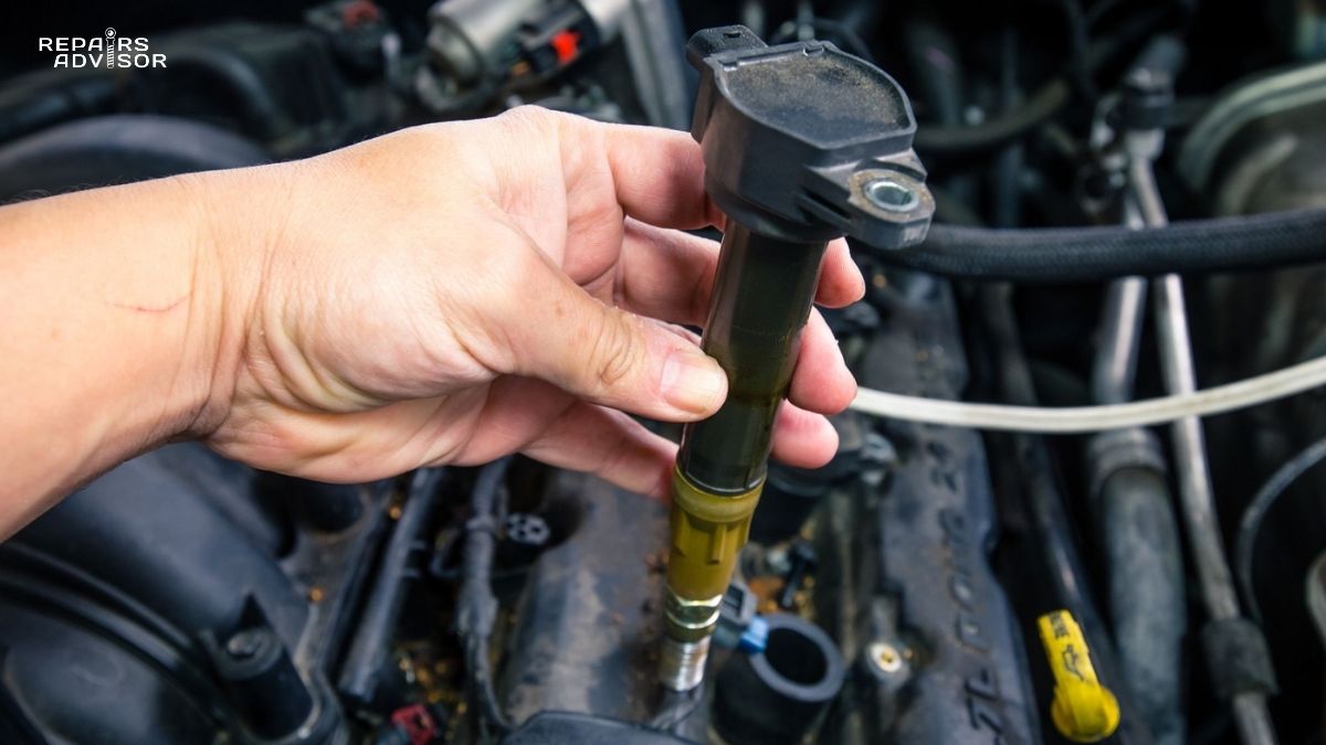
Ignition Coils form the voltage transformation heart of the system. These electromagnetic devices contain primary windings (approximately 200 turns of heavy wire) and secondary windings (up to 25,000 turns of fine wire) wrapped around iron cores. When the Engine Control Unit (ECU) interrupts current flow through the primary winding, the magnetic field collapse induces extremely high voltage in the secondary winding – sufficient to create spark across the plug gap.
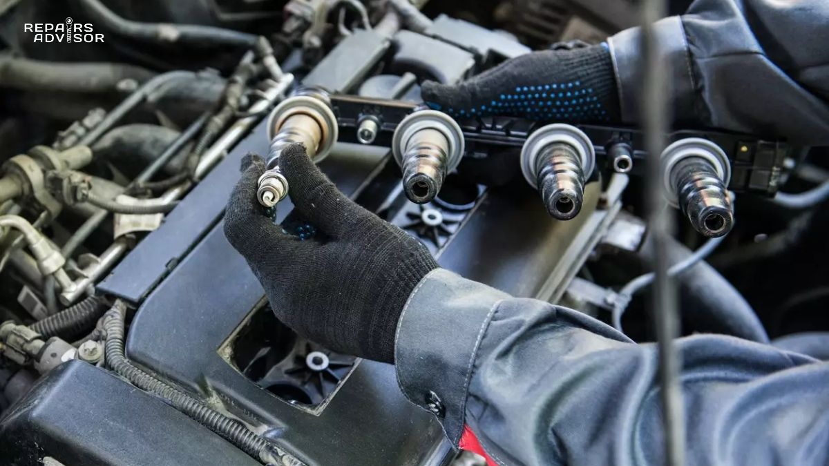
Spark Plugs serve as the final delivery mechanism for ignition energy. Each plug features a center electrode, ground electrode, ceramic insulator, and metal shell. The electrode gap (typically 0.028-0.060 inches) must be precisely maintained to ensure proper spark formation. The ceramic insulator prevents voltage leakage while withstanding extreme combustion temperatures and pressures.
Crankshaft Position Sensors provide critical timing reference signals to the ECU. These magnetic or Hall-effect sensors detect reluctor wheel teeth passing at predetermined crankshaft positions, enabling the ECU to calculate exact engine position and fire ignition coils at optimal timing.
Advanced Control Components
The Ignition Module or integrated ECU ignition control manages coil charging (dwell time) and firing sequences. Modern systems use individual coil-on-plug designs, eliminating mechanical distributors and spark plug wires while providing independent control over each cylinder’s ignition timing.
Knock Detection Systems incorporate piezoelectric sensors that detect engine knock (pre-ignition) vibrations. When knock occurs, the ECU immediately retards ignition timing to prevent engine damage, demonstrating the system’s sophisticated feedback control capabilities.
For comprehensive repair procedures and component specifications, refer to manufacturer-specific service documentation available through Honda Repair Manuals, Toyota Repair Manuals, or Ford Repair Manuals.
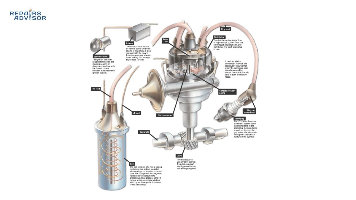
How Ignition System Works: Step-by-Step Operation
The ignition system operates through carefully orchestrated electrical and magnetic processes, converting 12-volt battery power into precisely timed high-voltage sparks. This transformation occurs thousands of times per minute with exact timing critical to engine performance.
Power-Up and System Initialization
When the ignition key turns to “ON,” the ECU initializes ignition system operations by performing component diagnostics and establishing communication with engine sensors. The system verifies crankshaft position sensor signals, camshaft position sensor inputs (for sequential firing systems), and ignition coil primary circuit integrity.
The ECU calculates initial ignition timing based on stored calibration maps, considering engine temperature, atmospheric pressure, and other environmental factors. This preparation ensures optimal spark timing from the moment cranking begins.
Coil Charging Sequence (Dwell Period)
During the dwell time phase, the ECU energizes each ignition coil’s primary winding, typically 2-8 milliseconds before the planned spark event. Current flow through the primary winding creates a strong magnetic field in the iron core, storing energy for subsequent spark generation.
Modern coil-on-plug systems charge individual coils independently, allowing precise dwell control optimized for each cylinder’s specific requirements. The ECU continuously adjusts dwell time based on engine speed, load, and electrical system voltage to ensure consistent spark energy across all operating conditions.
High-Voltage Generation and Spark Creation
At the precise ignition timing moment, the ECU instantly interrupts primary coil current. This sudden magnetic field collapse induces extremely high voltage (40,000-100,000 volts) in the secondary winding through electromagnetic induction principles.
The high voltage travels through the secondary circuit to the spark plug, where it overcomes the electrical resistance of the compressed air-fuel mixture in the gap between electrodes. The resulting electrical arc creates the spark that initiates combustion, with spark duration typically lasting 1-2 milliseconds.
Timing Control and Adaptation
The ECU continuously monitors engine conditions through multiple sensors, adjusting ignition timing in real-time for optimal performance. Timing control systems advance ignition timing under light loads for maximum efficiency and retard timing under heavy loads to prevent knock.
Advanced systems incorporate knock detection feedback, automatically reducing ignition advance when pre-ignition occurs. This closed-loop control protects the engine while maintaining optimal timing under varying fuel quality and operating conditions.
For detailed diagnostic procedures and timing specifications, consult Engine Management Systems guides or Spark Plug diagnostic information.
Ignition System Location and Access Guide
Locating ignition system components varies significantly between vehicle designs, but understanding typical locations enables efficient diagnosis and service. Modern vehicles predominantly use coil-on-plug configurations that integrate directly with engine valve covers, while some applications retain centralized coil packs with spark plug wires.
Coil-On-Plug System Access
Individual Ignition Coils mount directly above each spark plug, typically secured by single bolts or clips to the valve cover or cylinder head. Access usually requires removing engine covers, air intake ducting, or other components that obstruct coil visibility. Each coil features an electrical connector that must be carefully disconnected before coil removal.
Most coil-on-plug designs allow spark plug access after coil removal, though deep recessed plugs may require special tools. The integrated design eliminates spark plug wires but requires individual coil replacement when failures occur.
Centralized Coil Pack Systems
Some vehicles use coil pack assemblies mounted on or near the engine, distributing high voltage through spark plug wires. These systems typically mount to intake manifolds, valve covers, or dedicated brackets with multiple coils integrated into single housings.
Wire routing from coil packs to individual spark plugs must be maintained correctly, as incorrect firing order will cause severe engine performance problems. Wire numbers or color coding typically identify proper cylinder connections.
Sensor and Control Module Locations
Crankshaft Position Sensors typically mount near the harmonic balancer, flywheel, or crankshaft pulley, requiring access from below the vehicle or through wheel wells. These locations provide optimal reluctor wheel detection while protecting sensors from engine heat and vibration.
Ignition Control Modules (when separate from ECU) often mount to firewalls, fender wells, or intake manifolds with heat sink attachments. Some older systems place modules inside distributor housings, requiring distributor cap removal for access.
Safety and Access Considerations
Before accessing ignition components, always disconnect the battery negative terminal and allow engines to cool completely. Ignition systems retain high voltage even after engine shutdown, and hot components can cause serious burns.
Use appropriate tools rated for high-voltage work, and never touch ignition components with engines running. Compressed air can help clean debris from coil and plug wells before component removal, preventing contamination from falling into cylinders.
For specific access procedures and torque specifications, reference vehicle-specific service manuals from manufacturers like BMW Repair Manuals, Mercedes-Benz Repair Manuals, or Volkswagen Repair Manuals.
Related Reading
- How Spark Plugs Work: Ignition and Heat Range – Deep dive into electrode design and heat range selection
- How Ignition Coils Work: High Voltage Generation – Electromagnetic principles and coil-on-plug technology
- How Engine Management Systems Work: ECU and Sensor Networks – Integration with engine control systems
- How Crankshaft Position Sensors Work: Engine Timing – Timing reference and signal generation
- How Distributors Work: Classic Ignition Timing – Traditional ignition system operation
For comprehensive ignition system troubleshooting and repair procedures, explore our collection of automotive service manuals and technical guides.
This information is provided for reference only. Always consult manufacturer specifications and professional guidance for complex ignition system diagnosis and repair. Safety-critical electrical work should be performed by qualified professionals.