Your dashboard lights flicker, the starter cranks slowly despite a new battery, and the radio cuts out when you turn on the headlights. You’ve checked fuses, tested the battery, and inspected connections—but the problem persists. The culprit? Your vehicle’s ground system, the invisible network of return paths that completes every electrical circuit in your vehicle. While we obsess over power distribution—positive cables, fuses, and relays—we often overlook the ground side until something goes wrong. Understanding how ground systems work transforms electrical troubleshooting from frustrating guesswork into systematic problem-solving.
The ground system provides the return path for electrical current flowing through every component in your vehicle. Think of electricity as a circle: current flows from the battery or alternator through a component, then must return through the ground path to complete the circuit. Without a proper ground connection, electrical circuits cannot function—it’s that fundamental. Unlike household wiring with dedicated ground wires, automotive systems use the vehicle’s metal chassis and frame as a massive, low-resistance conductor to carry return current from hundreds of components simultaneously back to the power sources.
Your vehicle’s car battery and alternator rely on multiple ground paths working together. The battery negative terminal connects to the engine block or chassis through a heavy cable, establishing the primary ground reference point. From there, ground straps connect the engine to the chassis, and the chassis distributes ground connections to every corner of the vehicle through wiring harnesses and local ground points. This distributed network handles everything from the 200+ amps needed for starter motor operation to the milliamp-level signals from engine sensors. When ground paths fail—through corrosion, loose connections, or inadequate wire sizing—the results range from annoying electrical quirks to complete system failure that leaves you stranded.
Why Ground System Is Critical for Electrical Function
The ground system serves as the electrical backbone that completes every circuit in your vehicle, providing the return path for current from all components back to the power source. When your engine is off, current flows from the battery through an accessory and returns through the ground system to the battery negative terminal. When the engine runs, current flows from the alternator through components and returns through the ground path to the alternator case. Ground is the common connection point where the battery, alternator, and all electrical loads meet—it’s not just the battery negative terminal, but rather the vehicle’s chassis or frame that serves as this universal reference point.
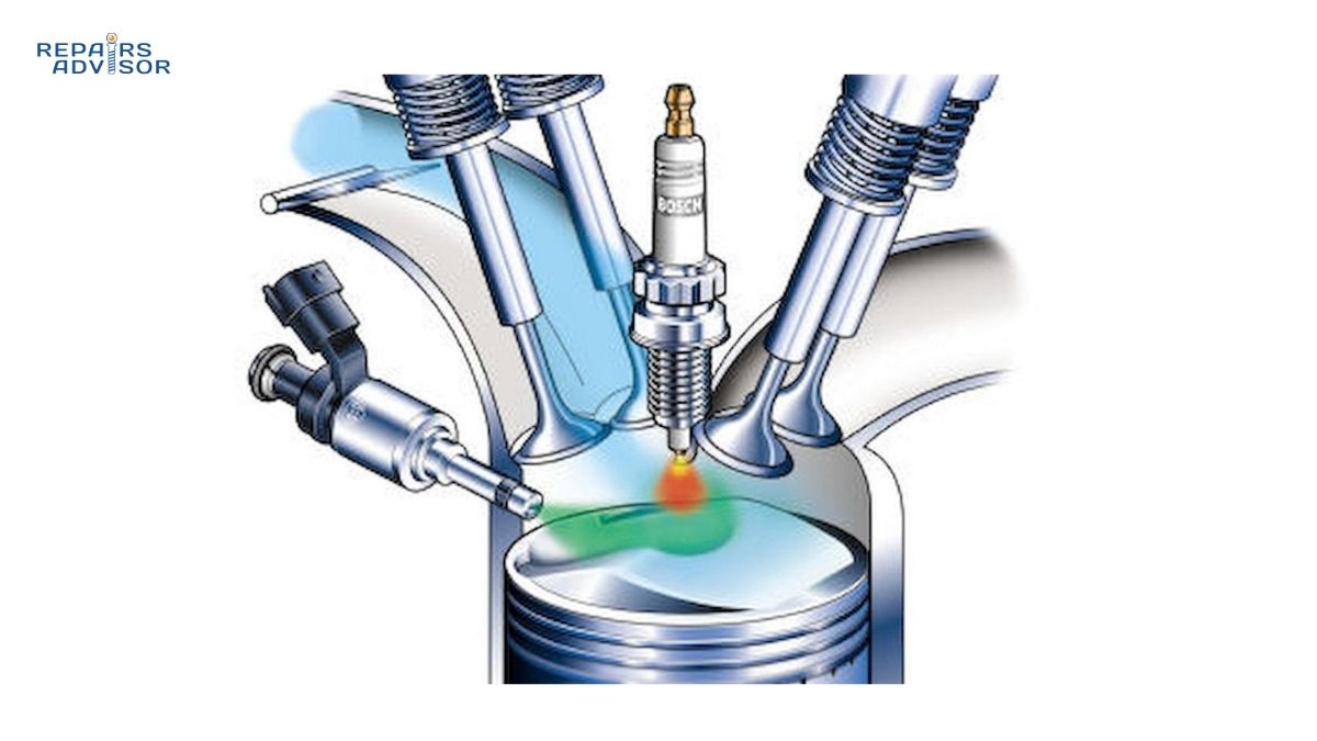
During starting, the electrical demands illustrate why ground paths must be robust. When you turn the ignition key, the starter motor draws 150-300+ amps from the battery. This massive current flows through the starter motor windings, then must return through the engine block, across the engine ground strap to the chassis, through the main battery ground cable, and back to the battery negative terminal. If any connection in this ground path has high resistance—from corrosion, loose bolts, or inadequate wire size—voltage drop occurs, reducing the effective voltage delivered to the starter motor. A ground path with just 1 ohm of resistance causes a 200-amp starter to lose 200 volts of potential (V = IR), though in a 12V system this manifests as reduced current and slow cranking.
The ground system provides more than just a current return path—it establishes the zero-volt reference point for all voltage measurements and sensor operations in your vehicle. Your engine control unit (ECU) measures sensor voltages relative to its ground connection. If the ground voltage shifts due to current flowing through a shared, resistive ground path (called ground offset), sensor readings become inaccurate. For example, if 100 amps of alternator charging current flows through a ground connection with 0.1 ohms of resistance, that creates a 10-volt offset (V = IR: 100A × 0.1Ω = 10V). Sensors that should read 0 volts at ground now see 10 volts, causing the ECU to receive corrupted data that leads to poor engine performance, misfires, or warning lights.
Modern vehicles specify ground conductor sizing to maintain voltage drops below 3% of system voltage—that’s 0.36 volts maximum in a 12-volt system. Professional technicians measure voltage drop by connecting a multimeter between a component’s ground terminal and the battery negative terminal while the component operates under load. Readings above 0.5 volts indicate excessive resistance requiring immediate attention. Common symptoms of ground system problems include dim or flickering lights (particularly noticeable when multiple accessories operate simultaneously), slow engine cranking even with a good battery, erratic gauge readings that jump or fluctuate, radio interference or alternator whine through speakers, ECU fault codes without corresponding component failures, and premature component failure from voltage stress.
Ground system failures create safety hazards beyond mere inconvenience. Without proper grounding, the vehicle chassis can become electrically “hot,” creating shock hazards when touching metal body panels. Airbag systems require clean grounds for reliable deployment—a critical safety concern in crashes. High-voltage hybrid and electric vehicles use sophisticated isolation monitoring that depends on proper grounding to detect dangerous ground faults before they become lethal. Poor ground connections generate excessive heat from resistance, creating fire hazards particularly in areas with flammable materials or fuel vapor. The ground system quite literally keeps your vehicle safe, functional, and reliable—making it deserving of the same attention we give to positive power distribution.
The electrical demands of modern vehicles stress ground systems beyond what was acceptable in older vehicles. Vehicles from the 1960s had minimal electrical loads—a 6-volt battery, simple lighting, and mechanical ignition sufficed. Today’s vehicles may have 200-amp alternators powering heated seats, infotainment systems, adaptive cruise control, and dozens of electronic control modules. Many manufacturers now use multiple ground distribution points with dedicated ground straps for specific systems. Automotive relays and high-current accessories require their own robust ground paths to prevent voltage drops from affecting sensitive electronics. Understanding ground system design and maintenance has become essential knowledge for anyone working on modern vehicles.
Ground System Parts and Construction Explained
A ground system consists of cables, straps, connection points, and the vehicle structure itself working together to provide low-resistance return paths for electrical current. The system begins with the main battery ground cable, typically 2-4 AWG (American Wire Gauge) for standard vehicles or 0-1 AWG for high-output electrical systems. This heavy-gauge copper cable connects the battery negative terminal directly to either the engine block or the vehicle chassis, establishing the primary ground reference point. The cable uses crimped or soldered ring terminals at both ends, with the battery end fitting over the negative battery post and the chassis end bolting to a designated ground stud or bolt. This connection must be clean, tight, and free from corrosion—any resistance here affects the entire electrical system.
The engine block ground strap provides the critical connection between the engine and chassis in all vehicles, regardless of battery location. This connection typically uses braided copper strapping 1-2 inches wide, or heavy cable of at least 4 AWG. The braided design allows flexibility to accommodate engine movement during acceleration and deceleration—engines torque significantly under load, moving several inches on their mounts. If the ground strap is too short or uses rigid cable, this movement can pull the connection apart or fatigue the conductor until it fails. The strap bolts to the engine block and connects to either the firewall, inner fender, or chassis rail depending on vehicle design. Some vehicles use multiple engine ground straps for redundancy or to provide separate paths for different electrical loads. This strap must handle hundreds of amps during starting, as the starter motor bolts directly to the engine block and relies on the engine-to-chassis ground for its return path.
Chassis ground points distribute grounding capability throughout the vehicle structure. These are bare metal studs, bolts, or welded mounting points strategically located in the engine compartment, interior, and trunk areas. Factory ground points often use star washers or serrated lock washers to bite through any oxidation and ensure metal-to-metal contact. Vehicle designers place these ground points near the accessories they serve, minimizing ground wire length and associated voltage drop. A fuel pump in the rear of the vehicle grounds to a local chassis point near the fuel tank rather than running a ground wire all the way to the engine compartment. This distributed approach creates multiple parallel current paths and prevents any single ground point from becoming overloaded.
Body-on-frame vehicles require special ground considerations because rubber bushings between the body and frame provide vibration isolation but also electrical isolation. In these vehicles, the frame typically serves as the primary ground distribution network, with heavy ground cables connecting the battery and engine to the frame. The body then requires a separate ground connection to the frame—usually a braided strap or heavy cable connecting the body to the frame at one or more points. Without this body-to-frame ground, accessories mounted to the body (interior lights, power windows, radio) cannot complete their ground path and will not function. Professional wiring harness design accounts for this by routing body accessory grounds to specific connection points near the body ground strap.
Unibody vehicles simplify the ground distribution challenge because the body structure itself serves as the frame—a single unified metal structure provides both structural support and ground distribution. However, unibody construction introduces its own challenges. Modern manufacturing uses spot welds spaced several inches apart and structural adhesives to bond panels together. These connections can introduce resistance in the ground path, as current must flow through relatively small weld spots rather than continuous metal-to-metal contact. Some manufacturers address this by installing supplemental ground straps across critical junctions, particularly in areas prone to corrosion or where high-current accessories mount. When adding aftermarket accessories to unibody vehicles, choosing ground points with good electrical connection to the main structure becomes important.
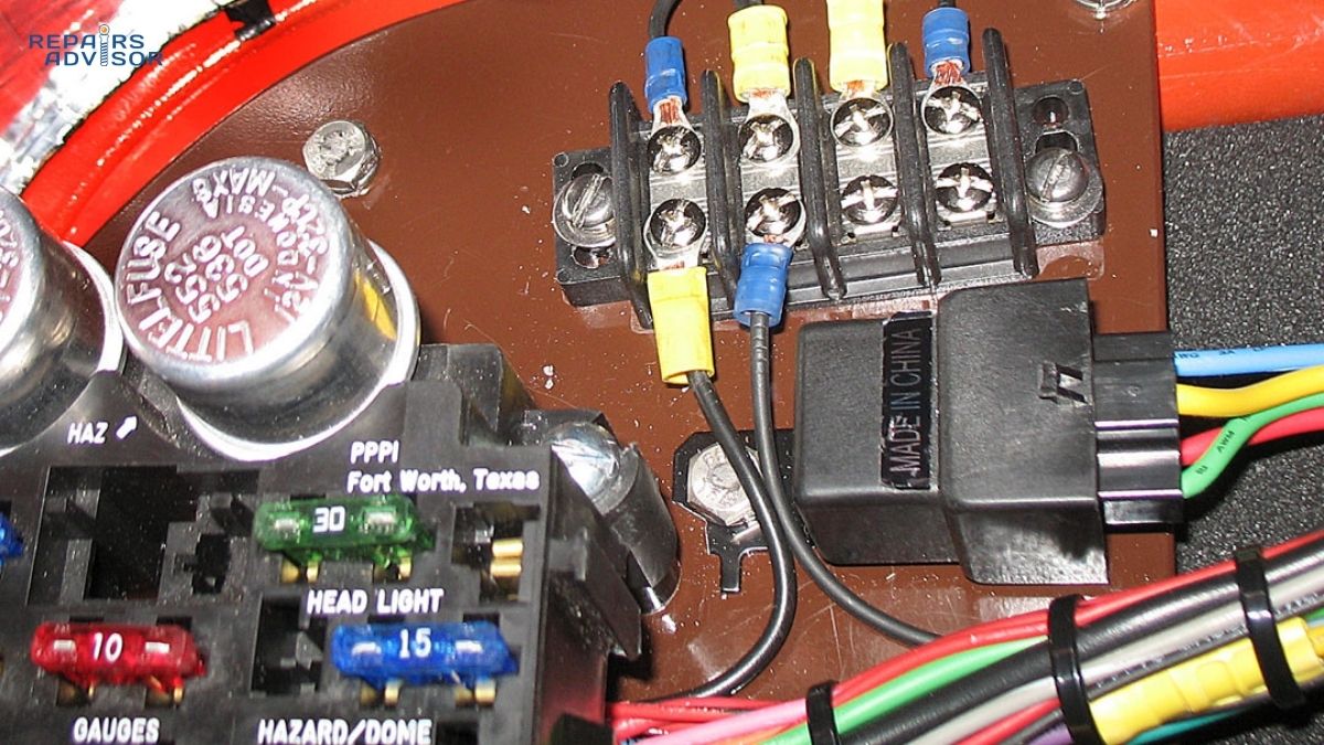
Professional electrical systems and aftermarket installations often use ground distribution blocks to centralize multiple ground connections. These blocks consist of a metal terminal block with a single large input connection from the main ground and multiple smaller output terminals for individual circuits. This approach offers several advantages: it eliminates the cluttered appearance of multiple wires bolted to a single chassis point, ensures all connected circuits share the exact same ground reference (no voltage differences between connection points), and simplifies troubleshooting by providing a single point to test all connected grounds. Custom audio installations frequently use distribution blocks to prevent ground loops that cause alternator whine through speakers.
Star-point grounding represents the gold standard for sensitive electronic systems, particularly engine control units and their sensor networks. In a star-point ground configuration, each device connects to a single common point through its own dedicated ground wire—no shared ground paths exist between different circuits. This prevents high-current circuits from affecting low-current sensitive electronics. The ECU sensor ground operates independently from power grounds, ensuring that starter motor current or alternator charging current cannot induce voltage offsets in sensor readings. Professional engine management system installations always specify star-point grounding, with sensor grounds connecting ONLY to the ECU sensor ground terminal, never to the engine block or chassis ground.
Wire sizing standards ensure ground paths can handle their current loads without excessive voltage drop or heat generation. The battery-to-engine ground cable requires 2 AWG minimum for standard vehicles, with 0-1 AWG for high-output systems (vehicles with amplifiers, winches, or upgraded alternators over 150 amps). Engine-to-chassis ground straps use 4 AWG minimum, though many manufacturers specify even heavier braided straps for additional capacity. Body ground connections use 8-10 AWG minimum, while accessory grounds should match or exceed the gauge of the power wire feeding that accessory—a component fed by 14 AWG power wire needs at least 14 AWG ground wire. Signal grounds for sensors and control modules typically use 16-18 AWG, which is sufficient for their milliamp-level current draws.
Material selection for ground conductors is critical. Copper provides the best conductivity and remains the only acceptable material for automotive ground wires—aluminum has higher resistance and is prone to corrosion at connections. Stranded wire is strongly preferred over solid wire because it resists vibration fatigue and remains flexible for routing around engine components. For ground wires longer than 6 inches, insulated wire protects against accidental short circuits and corrosion. Bare braided copper strap works well for short engine-to-chassis connections where flexibility and high current capacity are priorities. All connection points require clean, bare metal surfaces—paint, rust, and corrosion act as insulators that dramatically increase resistance.
How Ground System Works: Step-by-Step Operation
The ground system begins its operation the moment the battery negative terminal connects to the engine block or chassis, establishing the vehicle’s ground reference point at zero volts. All voltage measurements in the vehicle reference this point—when we say the battery measures 12.6 volts, we mean 12.6 volts relative to the ground reference. This primary ground cable provides the return path for all electrical current, creating the foundational circuit. During starting, when you turn the ignition key to engage the starter, the sequence demonstrates why ground paths must be robust. Current flows from the battery positive terminal through the ignition switch and starter solenoid, energizing the starter motor. The starter motor draws 150-300+ amps through its windings to spin the engine, and this massive current must return through the engine block, across the engine ground strap to the chassis, through the main battery ground cable, and back to the battery negative terminal to complete the circuit.
Once the engine starts and runs, the electrical system transitions to a different operating mode. The alternator now supplies electrical power for all vehicle systems while simultaneously recharging the battery. The alternator case mounts to the engine block and grounds through this mechanical connection, making the engine block the ground reference for alternator-generated current. Now when accessories operate, current flows from the alternator output terminal through the vehicle electrical system, through the accessory, and returns through the ground path to the alternator case. The battery remains in the circuit as an electrical buffer—it absorbs excess current when the alternator produces more than vehicle loads require, and supplies additional current during peak loads that exceed alternator output capacity. This is why both the battery and alternator must share the same ground reference point through robust connections.
Multiple parallel ground paths distribute return current across the vehicle chassis, taking advantage of the chassis’s massive cross-sectional area to create extremely low-resistance return paths. Unlike a single ground wire with fixed resistance, the chassis provides multiple current paths that work in parallel. The physics of parallel resistance (1/R_total = 1/R₁ + 1/R₂ + 1/R₃…) means that adding more ground points actually reduces total ground system resistance. For example, if three ground straps each have 0.1 ohm resistance and connect in parallel from engine to chassis, the combined resistance is only 0.033 ohms—one-third of any single strap’s resistance. This parallel distribution also spreads heat generation across multiple connection points rather than concentrating it in one location.
Body-on-frame vehicles require careful attention to current routing because rubber bushings between the body and frame create electrical isolation. In these vehicles, the frame serves as the primary ground distribution network. The battery ground cable connects to the frame, and the engine ground strap also connects to the frame, establishing the frame as the common ground reference. However, accessories mounted to the body—interior lights, power windows, radio, dashboard gauges—mount to a structure that’s electrically isolated from the frame by rubber bushings. These components require a dedicated body-to-frame ground connection, typically a heavy braided strap connecting the body to the frame at one or more points. Without this connection, current from body-mounted accessories cannot find a path back to the battery or alternator. The ignition system and other engine-mounted components use the engine block and frame as their ground paths, while body components use the body-to-frame connection.
Ground point selection becomes critical for different types of electrical loads. Heavy-load components like the starter motor and alternator ground directly to the engine block, providing the shortest, lowest-resistance path for their hundreds of amps of current. This minimizes voltage drop and ensures maximum performance. Medium-load components including fuel pumps, cooling fans, and heater blowers ground to chassis points near their mounting locations, using 8-12 AWG ground wires. This distributed approach reduces voltage drop by minimizing wire length—a 15-foot ground wire has more resistance than a 3-foot ground wire of the same gauge. Low-load but noise-sensitive components like the ECU, sensors, and audio systems require special grounding considerations. These components use star-point grounding where sensor grounds connect ONLY to the ECU sensor ground terminal, never to the engine block or chassis. This isolation prevents high-current circuits from inducing voltage offsets on sensitive sensor signals.
The ground system establishes the zero-volt reference point that makes accurate voltage measurements possible. The ECU measures sensor voltages relative to its sensor ground connection. A throttle position sensor might output 0.5 to 4.5 volts depending on throttle opening, with the ECU interpreting these voltages relative to its sensor ground. If the sensor ground voltage shifts due to current flowing through a shared ground path (creating what’s called ground offset), the sensor readings become inaccurate. Consider this example: if 100 amps of alternator charging current flows through a ground connection with 0.1 ohm resistance, Ohm’s Law (V = I × R) tells us this creates a 10-volt drop across that resistance. Suddenly the “ground” reference isn’t at 0 volts anymore—it’s at 10 volts. Sensors that should read 0-5 volts now appear to the ECU as 10-15 volts, causing the ECU to receive completely incorrect data that results in poor engine performance or fault codes.
Star-point grounding solves this problem by ensuring that high-current power grounds and low-current signal grounds never share the same path. In a properly designed star-point system, all ECU sensor grounds connect through individual wires to a single common point at the ECU. The ECU’s power ground connects through a separate, heavy-gauge wire directly to the engine block or chassis. These two ground systems—power and signal—meet only at the battery negative terminal, which means high starter motor or alternator currents flowing through the power ground paths cannot create voltage offsets in the signal ground path. This is why vehicle network systems and modern engine management systems specify never grounding sensors directly to the engine block—doing so would bypass the isolation that star-point grounding provides.
Electromagnetic interference (EMI) control represents another critical function of proper grounding. When a component grounds at two different points, it creates what’s called a ground loop. Since different ground points on a large chassis may have slightly different voltages (due to current flows creating small voltage drops), current flows through the chassis between these ground points. This current loop acts as an antenna, both radiating electromagnetic noise and picking up interference from other electrical systems. The solution is to ground each component at only ONE point, breaking the loop. Shielded cables—commonly used for oxygen sensors, wheel speed sensors, and communication networks—should have their shields grounded at only one end (typically at the ECU) to prevent ground loops through the shield. Ford and other manufacturers provide detailed grounding diagrams showing the single designated ground point for each system.
Heat generation in ground connections becomes significant under high-current loads. Current flowing through any resistance generates heat according to the formula P = I²R (power equals current squared times resistance). A ground connection with even a small amount of resistance (0.1 ohm) carrying 200 amps of starter current generates 4,000 watts of heat (P = 200² × 0.1 = 4,000W). This explains why poor ground connections—corroded terminals, loose bolts, undersized wire—can melt insulation, damage terminals, or even start fires. The heat degrades the connection further in a positive feedback cycle: resistance causes heat, heat increases resistance and damages the connection, increased resistance causes more heat. Proper ground connections with clean, tight terminals and adequate wire gauge minimize resistance and safely dissipate the modest heat that does generate. Multiple parallel ground paths share the current load, reducing the current through any single path and the associated heat generation at each connection point.
Ground System Location and Access Guide
The battery ground cable serves as the primary ground connection in your vehicle, and locating it requires finding the path from the battery negative terminal to either the engine block or chassis. On most vehicles, this heavy black cable (2-4 AWG typical) runs from the battery negative terminal to a stud or bolt on the engine block, often near the starter motor mounting area. Some vehicles ground the battery negative terminal directly to the chassis at a point near the battery tray, particularly in vehicles with rear-mounted batteries. The cable typically routes under the battery tray or along the inner fenderwell to reach its connection point. You can identify it as the heaviest gauge black cable from the battery, with a large ring terminal or cable lug at the connection end.
Accessing the battery ground cable requires basic hand tools. You’ll need a battery terminal wrench or standard combination wrench (typically 10mm) to remove the connection at the battery negative terminal, and a socket wrench (commonly 13-15mm) to remove the bolt at the engine block or chassis connection point. Before disconnecting any ground connections, always remove the battery negative terminal first—this prevents accidental short circuits if your tools touch both the positive terminal and ground simultaneously. Use a wire brush to clean both the cable terminals and the mounting surfaces, removing any corrosion, paint, or oxidation. These surfaces must make clean metal-to-metal contact. After reconnection, apply a thin coat of dielectric grease or anti-corrosion spray to protect against future corrosion, particularly in humid or salt-exposed environments.
The engine ground strap provides the critical connection between the engine block and chassis, accommodating engine movement while maintaining low-resistance ground continuity. The most common location runs from the engine block or cylinder head to the firewall, creating a short, direct path. You’ll find this strap by looking for a flat braided copper strap (typically 1-2 inches wide) or heavy cable connecting between the engine and the vehicle body or frame. Some Toyota and Honda vehicles place this strap from the engine block to the inner fenderwell or strut tower. Body-on-frame trucks often use the transmission bell housing area as an additional ground point to the chassis frame.
Engine ground strap locations vary significantly by vehicle configuration. Front-wheel-drive vehicles typically use shorter ground straps due to the transverse engine mounting, connecting the engine to the nearby firewall or inner fender panel. Rear-wheel-drive vehicles may have longer straps running from the engine block to the firewall, and often include an additional ground from the transmission to the chassis frame. All-wheel-drive vehicles sometimes use multiple ground straps—one for the engine, one for the transfer case, and potentially another for the rear differential if it’s mounted with isolated bushings. The ground strap appears as a flat braided copper conductor, which may be bare copper showing its distinctive orange-brown color or covered with a thin protective coating. Both ends have bolt holes or ring terminals, with paint or coating deliberately removed at the contact points for clean metal-to-metal connection.
Chassis ground points distribute throughout the vehicle to provide local grounding for accessories and components. In the engine compartment, look for studs or bolts on the inner fenderwell, firewall, and radiator support structure. These often have multiple ground wires already connected, indicating factory-designated ground points. Interior ground points appear on the dashboard structure beneath the dash panel, on seat rail mounting points, or on the center console mounting brackets. Trunk areas typically have ground points on the quarter panel structure or near the taillight mounting areas. Factory ground points frequently feature bare metal with star washers or lock washers to ensure solid contact, and may have identifying marks or part numbers cast into the surrounding metal.
Identifying good chassis ground points requires looking for specific characteristics. The metal surface should be bare—free of paint, powder coating, or corrosion—to allow direct metal-to-metal contact. Existing ground wires connected to a point indicate it’s a factory-designed ground location. The mounting point should be solidly welded or bolted to the main chassis or body structure, not a loosely-attached bracket or removable panel. Some Chevrolet and GM vehicles have dedicated ground studs that protrude from the firewall or fender wells specifically for grounding purposes. When adding aftermarket accessories, choose ground points close to the accessory to minimize wire length and voltage drop, and ensure the connection point connects solidly to the vehicle structure.
Fiberglass-bodied vehicles present unique grounding challenges because the non-conductive fiberglass body provides no ground path. Hot rods, kit cars, and some specialized commercial vehicles fall into this category. These vehicles require custom ground distribution systems with ground wires running from the engine block to all accessory locations. A typical setup includes one ground wire to the rear of the vehicle for rear lighting and fuel pump, two ground wires to the dashboard area for instruments and accessories (more if the vehicle has extensive electrical equipment), and one ground wire to the front for headlights and grille-mounted accessories. Each ground wire can connect to a distribution block at its destination, with individual accessories grounding to that local distribution point. This approach centralizes grounding while avoiding the cluttered appearance of dozens of wires bolted directly to the engine block.
Safety equipment and precautions become paramount when working with ground systems. Always wear safety glasses to protect against battery acid splashes and flying debris when cleaning corroded connections. Use insulated gloves when working near the battery, as even the “ground” side of the electrical system carries full current. Disconnect the battery negative terminal before performing any ground system work—this prevents short circuits if tools accidentally contact both positive and ground connections simultaneously. Ensure the vehicle is on a level surface and properly supported if you need to access underbody ground connections. Never work under a vehicle supported only by a jack; use properly-rated jack stands.
Accessing and servicing ground systems requires specific tools for effective work. A socket set covering 8mm through 19mm handles most ground connection bolts. Combination wrenches in the same range provide access in tight spaces where sockets won’t fit. A wire brush or sandpaper prepares connection surfaces by removing corrosion and exposing clean metal—this step is critical for low-resistance connections. A digital multimeter enables testing for continuity and voltage drop, helping diagnose ground problems systematically. A torque wrench ensures proper tightening of ground connections to manufacturer specifications—overtightening can damage threads or break studs, while undertightening allows corrosion to form and increases resistance.
Professional service becomes necessary for certain ground system work that exceeds DIY capabilities. ECU grounding modifications or diagnosis of complex ground-related fault codes require professional scan tools and expertise. Installing star-point grounding systems for performance engine management requires understanding electrical theory and proper implementation techniques. Hybrid and electric vehicle grounding MUST be performed only by certified technicians—these systems involve high voltage that can be lethal, and orange-colored wiring indicates high-voltage components that should never be touched without proper training and equipment. Custom high-power audio system installations often benefit from professional ground system design to prevent noise and ensure adequate current capacity.
Specific safety warnings apply to ground system work. NEVER work on hybrid or electric vehicle high-voltage grounds without proper certification and equipment. High-voltage systems in these vehicles can deliver fatal electric shocks even when the vehicle appears off. Orange cables and components indicate high-voltage systems that require specialized training. Always disconnect the battery negative terminal before removing any ground cables to prevent short circuits and component damage. Never rely solely on the vehicle frame as a ground path without verifying all connections—rubber body mounts, loose connections, or corroded joints can interrupt ground paths. Corroded ground connections represent fire hazards because the increased resistance generates heat that can ignite nearby materials or fuel vapors.
Professional consultation becomes advisable in several situations. If you experience persistent electrical issues even after inspecting and cleaning visible ground connections, the problem may lie in hidden ground paths that require diagnostic equipment to locate. A complete ground system audit with professional voltage drop testing can identify marginal connections before they fail completely. Hybrid or electric vehicles require specialized diagnostic tools and safety equipment that justify professional service rather than DIY attempts. Complex aftermarket electrical installations—performance engine management systems, high-output charging systems, or extensive accessory additions—benefit from professional electrical system design that properly distributes ground loads. When in doubt, the cost of professional diagnosis and repair is far less than the cost of damaged electronic components or a vehicle fire from a ground system failure.
The 12V battery in your vehicle depends entirely on the ground system to complete its circuits and enable electrical flow. Whether you’re working on a modern BMW with sophisticated electronics or a classic vehicle with simpler electrical demands, the ground system principles remain the same. Understanding ground system locations and access requirements empowers you to perform basic maintenance while recognizing when professional service is the safer, more effective choice.
Conclusion
The ground system serves as the electrical foundation that enables every circuit in your vehicle to function, providing the return path for current from all components back to the battery and alternator. This distributed network of cables, straps, and chassis connections works invisibly until something fails—then the consequences range from annoying electrical quirks to complete system failure that leaves you stranded. The primary ground cable connecting the battery negative terminal to the engine block or chassis establishes the ground reference point for the entire vehicle. From there, the engine-to-chassis ground strap handles high starter motor current while accommodating engine movement, and multiple chassis ground points distribute grounding capability throughout the vehicle for local accessories. In body-on-frame vehicles, the critical body-to-frame ground connection enables body-mounted accessories to complete their ground path across the rubber-isolated body/frame joint.
Common ground system problems stem from environmental factors and inadequate maintenance. Corrosion at battery terminals and chassis connection points increases resistance, causing voltage drops that reduce component performance. The engine ground strap represents the single most common ground system failure point—this critical connection can break from fatigue, corrode at the connection points, or pull apart if too short to accommodate engine movement. Modified vehicles or those with added accessories frequently suffer from insufficient grounding as the factory ground system wasn’t designed to handle the additional current loads. Ground offset in ECU systems occurs when high-current power grounds and low-current sensor grounds share paths, allowing charging system or starter motor current to create voltage offsets that corrupt sensor readings. Electrical noise manifests as radio interference, alternator whine through speakers, or poor engine performance when ground loops form through components grounded at multiple points. Paint, rust, or corrosion at connection points acts as an insulator blocking current flow and causing the same symptoms as a loose or broken ground.
Maintaining your ground system requires regular attention but involves straightforward procedures. Inspect all visible ground connections during battery service or oil changes—look for corrosion, loose bolts, or damaged cables. Clean connection points annually, especially in humid climates or areas that use road salt, which accelerates corrosion. Remove the battery negative terminal first to prevent short circuits, then clean both the cable terminal and chassis connection point with a wire brush until you see clean, shiny metal. Tighten all ground connections securely after cleaning, ensuring metal-to-metal contact without paint or corrosion interfering. Check that the engine ground strap remains secure at both ends and shows no signs of fraying, corrosion, or damage. If you’re adding aftermarket accessories, verify that the existing ground system can handle the additional load—high-current accessories may require dedicated ground wires rather than sharing existing ground points.
Professional voltage drop testing provides definitive diagnosis when electrical problems suggest ground issues. Using a multimeter, technicians measure the voltage difference between a component’s ground terminal and the battery negative terminal while the component operates under load. Readings should be less than 0.5 volts; anything higher indicates excessive resistance requiring repair. This testing identifies marginal connections before they fail completely, preventing the frustration of intermittent electrical problems that are difficult to diagnose. Modern diagnostic scan tools can also detect ground-related fault codes, particularly in engine management systems where sensor ground issues manifest as implausible sensor readings or conflicting data.
Ground system problems can cause complete electrical failure, leaving you stranded far from help. The warning signs are clear: dimming lights when operating multiple accessories, slow cranking despite a good battery, gauge readings that fluctuate or behave erratically, radio interference that changes with engine speed or electrical load, difficulty starting particularly when the engine is hot, and dashboard warning lights illuminating without corresponding component failures. Any of these symptoms warrants immediate ground system inspection—the problem typically worsens over time as corrosion spreads or loose connections damage from arcing.
While inspecting ground connections represents straightforward DIY maintenance, testing for voltage drop and diagnosing complex grounding problems requires professional diagnostic equipment and expertise. The automotive electrical system has become increasingly complex, with multiple control modules communicating over networks and sophisticated sensors requiring clean ground references. What appears as an engine performance problem may actually stem from ground offset affecting sensor readings. Professional technicians have the diagnostic tools and knowledge to systematically test ground paths, identify high-resistance connections, and verify proper ground distribution. The cost of proper diagnosis prevents expensive misdiagnosis—replacing sensors, modules, or other components when the actual problem is a corroded ground connection wastes time and money.
NEVER work on hybrid or electric vehicle high-voltage grounding systems—these systems operate at voltages that can be immediately lethal and require specialized certification, safety equipment, and procedures. Orange-colored wiring and components indicate high-voltage systems that must only be serviced by certified technicians. Even experienced automotive technicians must complete additional training and certification before working on high-voltage vehicle systems. The risks are simply too high for DIY attempts.
For vehicle-specific ground point locations, wire gauge specifications, and testing procedures, consult your repair manual. Each manufacturer designs ground systems differently based on vehicle architecture, electrical loads, and component placement. Smart power distribution systems in modern vehicles use sophisticated electronic control of power distribution, but still rely entirely on proper grounding for operation. The ground system remains fundamental regardless of technological advancement. Professional diagnosis ensures proper ground system function and prevents component damage from voltage-related stress. Your vehicle’s electrical system depends on these invisible connections—giving them the attention they deserve prevents problems and ensures reliable operation for years to come.
Understanding how ground systems work transforms electrical troubleshooting from frustrating guesswork into systematic problem-solving, empowering you to maintain this critical system properly while knowing when to seek professional help for complex issues. Visit the automotive electrical system category for more technical guides on vehicle electrical systems and components.