Despite the widespread adoption of disc brakes on modern vehicles, drum brakes remain a critical component of automotive braking systems. Found primarily on the rear wheels of passenger cars and light trucks, drum brakes offer a unique combination of cost-effectiveness, durability, and powerful stopping force that continues to make them relevant in today’s automotive landscape. Their enclosed design protects internal components from road debris and moisture while providing the mechanical foundation for integrated parking brake systems.
Understanding how drum brakes work reveals an elegant mechanical system that leverages physics to multiply braking force through self-energizing action. This servo effect allows drum brakes to generate powerful stopping force without requiring excessive hydraulic pressure, making them particularly effective for rear-wheel applications where cost and reliability are prioritized over ultimate performance. Whether you’re maintaining your own vehicle, diagnosing brake issues, or simply curious about automotive technology, this comprehensive guide will walk you through every aspect of drum brake construction, operation, and maintenance.
In this article, you’ll learn about the critical components that make up drum brake assemblies, how the self-energizing effect multiplies braking force, the different types of drum brake configurations used across vehicle applications, and practical guidance for inspection and maintenance. We’ll also compare drum brakes to disc brake systems to help you understand when each technology excels, and provide essential safety information for DIY mechanics considering brake service work.
Why Drum Brakes Are Critical to Vehicle Safety
Drum brakes serve as the primary rear-wheel braking system on millions of vehicles worldwide, playing an essential role in overall vehicle safety and control. Their fundamental purpose is to convert kinetic energy from the moving vehicle into thermal energy through friction, effectively slowing or stopping wheel rotation. In typical hybrid disc/drum configurations, drum brakes handle approximately 30-40% of total braking force while providing 100% of parking brake functionality, making them far more than just a cost-saving compromise.
Primary Safety Functions
The safety criticality of drum brakes extends beyond basic stopping power. They provide reliable rear wheel braking that complements front disc brakes in the vast majority of passenger vehicles, creating a balanced braking system that prevents premature rear wheel lockup during emergency stops. This front-biased braking distribution protects against dangerous rear-end skids that could cause loss of vehicle control. Additionally, drum brakes generate consistent stopping power in both forward and reverse directions due to their symmetrical shoe geometry, unlike some disc brake systems that may exhibit directional sensitivity.
Perhaps most importantly, drum brakes naturally integrate with mechanical parking brake systems through cable-actuated lever mechanisms built directly into the brake shoe assembly. This mechanical connection provides a fail-safe parking brake that operates independently of the hydraulic system, ensuring vehicles can be securely held on inclines even if hydraulic pressure is lost. This integration is so valuable that even some vehicles with four-wheel disc brakes retain small drum-in-hat parking brake assemblies within the rear rotors.
Advantages Over Disc Brakes
Drum brakes offer several distinct advantages that explain their continued widespread use. Cost-effectiveness stands as the primary driver, with drum brake systems typically costing 40-60% less to manufacture and service compared to equivalent disc brake assemblies. This cost advantage stems from simpler caliper-less design, lower-cost friction materials, and reduced precision machining requirements. For automakers producing millions of vehicles annually, these savings are substantial without compromising safety performance for rear-wheel applications.
The self-energizing effect represents drum brakes’ most significant technical advantage. When brake shoes contact the rotating drum, the drum’s rotation physically helps wedge the leading shoe more tightly against the friction surface. This servo action can multiply applied force by 2-3 times beyond what hydraulic pressure alone provides, allowing drum brakes to generate powerful stopping force from relatively compact, lightweight components. A 10-inch diameter drum brake can produce braking force equivalent to a much larger disc brake system simply by leveraging this mechanical advantage.
Durability and longevity further favor drum brakes in appropriate applications. The enclosed design protects brake shoes, wheel cylinders, and return springs from road salt, water spray, mud, and debris that would rapidly degrade exposed disc brake components. This protection translates to longer service intervals, with properly maintained drum brake shoes often lasting 250,000-300,000 kilometers before requiring replacement—significantly longer than typical disc brake pads. The larger friction contact area distributes heat and wear across a greater surface, contributing to extended component life.
Modern Applications and Evolution
Today’s drum brakes serve specific roles where their advantages outweigh their limitations. The most common application is rear brakes on front-wheel drive passenger vehicles equipped with front disc brakes. This configuration provides optimal braking performance: disc brakes deliver superior stopping power and heat management at the front wheels (which handle 60-70% of braking force), while drum brakes offer cost-effective, durable rear braking with integrated parking brake functionality.
Light-to-medium duty trucks and commercial vehicles continue using drum brakes when load-carrying capacity and parking brake holding power take priority over ultimate performance. The self-energizing action proves particularly valuable for vehicles that frequently operate at gross vehicle weight, as the servo effect helps generate adequate braking force without requiring massive hydraulic systems or exotic friction materials.
Interestingly, electric and hybrid vehicles represent a growing market for drum brakes. These vehicles rely heavily on regenerative braking systems for normal deceleration, dramatically reducing mechanical brake usage. Since drum brakes already excel at durability and can easily handle the reduced duty cycle, automakers like Toyota, Volkswagen, and others equip many EV and hybrid models with rear drum brakes to save cost and weight without compromising safety. The enclosed drum design also generates less particulate matter than disc brakes, providing an environmental benefit.
Safety Note for DIY Mechanics: While intermediate-skill DIY enthusiasts can safely inspect drum brakes for wear and damage, brake shoe replacement and adjustment require proper tools, knowledge of spring mechanisms, and understanding of adjustment procedures. First-time DIY mechanics should seek guidance from experienced technicians or professional supervision when performing drum brake service work. Improper reassembly can result in brake failure or uneven braking that compromises vehicle safety.
Drum Brake Components and Construction
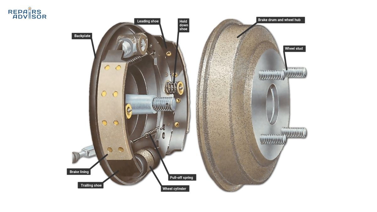
A complete drum brake assembly contains approximately 15-20 individual components working together to convert hydraulic pressure into mechanical braking force. Understanding each component’s construction and function provides the foundation for diagnosing issues, performing maintenance, and appreciating the elegance of this time-tested design. Let’s examine each critical component in detail.
Brake Drum
The brake drum serves as both the rotating component and the friction surface for the entire assembly. Mounted directly to the wheel hub via lug studs, the drum rotates at wheel speed and provides the cylindrical inner surface against which brake shoes press to generate stopping force. Modern brake drums are manufactured from special gray cast iron with graphite content, a material chosen for its exceptional heat conductivity, wear resistance, and ability to maintain consistent friction characteristics across a wide temperature range.
Typical passenger vehicle brake drums measure 9-11 inches in diameter and 2-3 inches in width, with wall thickness of approximately 0.25-0.375 inches. This substantial mass serves dual purposes: providing structural rigidity to resist distortion under braking loads, and acting as a heat sink to absorb and dissipate thermal energy generated by friction. The drum’s thermal mass allows it to absorb intense heat bursts during hard braking without immediately overheating, though sustained braking can eventually lead to heat saturation and brake fade.
Maximum allowable drum diameter specifications are permanently stamped or cast into the drum’s outer edge, typically indicating that the drum must be replaced when internal diameter exceeds 0.120 inches beyond original specification. This limit prevents excessive drum thickness loss that would compromise structural integrity and heat management. Some performance-oriented drums incorporate cooling fins or ventilation holes on the outer circumference to improve heat dissipation, though these features are less common on passenger vehicle applications.
The drum’s inner friction surface must maintain precise cylindrical geometry and smooth finish for proper brake operation. Manufacturing tolerances typically hold internal diameter variations to less than 0.005 inches around the circumference. Any deviation from true cylindrical shape—caused by overheating, improper installation, or wear—results in pulsating brake pedal feel and uneven shoe wear. Regular measurement during brake service using specialized drum micrometers ensures drums remain within specifications.
Brake Shoes: Primary and Secondary
Brake shoes are the friction-generating heart of drum brake assemblies, consisting of two crescent-shaped steel pieces welded together to create a rigid structure that can withstand substantial applied forces. Each brake assembly uses two shoes—designated primary (leading) and secondary (trailing)—that work together to generate braking force through carefully engineered geometric relationships. The shoes pivot at anchor points and slide radially to contact the drum’s inner surface when hydraulic pressure is applied.
The primary shoe faces the front of the vehicle and experiences the full benefit of self-energizing action during forward braking. Drum rotation in the forward direction physically pulls this leading shoe more tightly against the friction surface, multiplying the force from the wheel cylinder piston. This self-servo effect makes the primary shoe the dominant friction generator in most drum brake designs, and it typically shows greater wear than the secondary shoe over time.
The secondary shoe faces the rear of the vehicle and works against drum rotation during forward braking, experiencing negative servo action that reduces its effective contribution. To compensate for this reduced mechanical advantage, secondary shoes often use different friction material compounds or greater lining thickness compared to primary shoes. During reverse vehicle motion, the shoes reverse roles—the secondary becomes leading and the primary becomes trailing—ensuring consistent braking performance regardless of travel direction.
Friction material bonded or riveted to each shoe’s outer surface typically measures 3-5 millimeters thick when new, depending on application. Modern friction compounds use carefully formulated mixtures of organic fibers, ceramic materials, metallic particles, and friction modifiers to achieve optimal performance across the operating temperature range of 150-600°F. The material must provide consistent friction coefficient, resist fade at elevated temperatures, and wear gradually without gouging the drum surface. Semi-metallic and ceramic formulations have largely replaced asbestos-based linings that were common decades ago.
The shoe’s web structure contains precisely positioned holes and slots that accommodate return springs, hold-down hardware, parking brake linkage, and automatic adjustment mechanisms. All application force from the wheel cylinder pistons transfers through this web to the friction-bearing lining table, making structural rigidity essential. The shoe edges feature three “V”-shaped notches or tabs (nibs) that rest against support pads on the backing plate, providing the pivot points that allow shoes to swing outward during brake application while maintaining proper positioning.
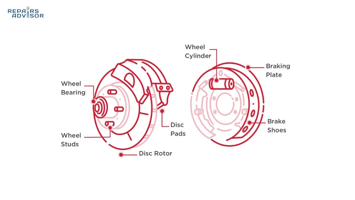
Wheel Cylinder
The wheel cylinder serves as the critical interface between the hydraulic brake system and mechanical brake shoe movement, converting pressurized brake fluid into the linear force that pushes shoes outward against the drum. This compact assembly measures approximately 1.5-2 inches in diameter and 2-3 inches in length, yet generates hundreds of pounds of force when actuated. The cylinder body is typically cast from aluminum or iron, with precision-bored cylinder walls that house the piston assemblies.
Inside the wheel cylinder housing, two pistons operate in opposition to each other, with one piston pushing each brake shoe. Each piston consists of a metal or composite plunger fitted with a rubber piston cup that seals against the cylinder bore, preventing fluid leakage while allowing the piston to slide freely during actuation. The rubber cup design creates a hydraulic seal in one direction while allowing trapped air to escape around the cup edges during bleeding procedures. Spring-loaded dust boots at each end of the cylinder protect the piston surfaces from moisture, dirt, and corrosion.
Dual-piston wheel cylinders represent the most common configuration, using two pistons housed within a single cylinder body positioned at the top of the backing plate assembly. When hydraulic pressure from the master cylinder reaches the wheel cylinder, it acts equally on both piston cups, forcing the pistons to move outward in opposite directions. This simultaneous outward motion pushes both brake shoes against the drum at the same instant, ensuring balanced force application.
Alternative wheel cylinder designs exist for specialized applications. Single-piston cylinders use one large-diameter piston to actuate a single shoe, typically in conjunction with fixed pivot points for the other shoe. This configuration appears in some duo-servo brake designs where the shoes are mechanically linked. Double-acting cylinder designs incorporate pistons that can move in both directions depending on hydraulic pressure routing, enabling both shoes to function as leading shoes regardless of vehicle direction—a feature used in twin-leading shoe configurations.
A bleeder valve positioned at the highest point of the wheel cylinder allows technicians to purge air from the hydraulic system during brake service. This small 7-8mm hex valve must remain closed during normal operation to prevent fluid leakage, opening only during bleeding procedures to release trapped air that would otherwise compress under pressure and create a spongy brake pedal feel. Proper bleeding technique ensures solid hydraulic coupling between brake pedal and wheel cylinder operation.
Backing Plate
The backing plate provides the rigid foundation upon which all drum brake components mount, serving as the structural backbone of the entire assembly. Manufactured from 3-4 millimeter thick stamped steel, this circular plate bolts directly to the vehicle’s axle housing or suspension components, creating a fixed reference point against which brake shoes can react. Without this rigid mounting base, brake shoes would simply push against flexible suspension components rather than generating effective braking force against the drum.
The backing plate’s circular design incorporates precisely positioned mounting holes, support pads, and raised tabs that locate and secure each brake component. Shoe support pads at the 12 o’clock and 6 o’clock positions provide smooth bearing surfaces against which the shoe nibs slide during brake application. The anchor pin or anchor plate—typically mounted at the bottom of the assembly—provides the fixed pivot point that enables self-energizing action by preventing shoe rotation with the drum. Mounting holes positioned around the perimeter allow bolting to the axle or suspension with exact alignment to ensure the backing plate remains perpendicular to the drum axis.
Beyond its structural role, the backing plate functions as a protective shield that prevents road debris, water spray, and mud from contaminating the brake shoe friction surfaces. This protection significantly extends component life compared to exposed disc brake systems, as the enclosed environment shields friction materials from corrosive road salts and abrasive contaminants. However, this same enclosed design also traps heat, limiting cooling capacity compared to open disc brake designs.
Several mounting holes in the backing plate accommodate the wheel cylinder, parking brake components, automatic adjustment mechanisms, and various brackets. The wheel cylinder typically mounts at the top of the assembly with two bolts, positioning it to push both shoes outward simultaneously. Parking brake cable guides and retaining clips integrate into the backing plate structure, routing mechanical parking brake cables to the brake shoe lever mechanisms. Access holes allow inspection of lining thickness without complete disassembly, though these inspection windows are less common on modern designs.
Return Springs and Hold-Down Hardware
Return springs and hold-down hardware create the mechanical intelligence that allows brake shoes to automatically return to rest position after each brake application, preventing drag that would cause excessive heat, wear, and fuel consumption. This seemingly simple spring arrangement incorporates careful engineering to balance multiple requirements: strong enough to ensure complete shoe retraction, yet not so strong that they require excessive hydraulic pressure to overcome during brake application.
The upper return spring—positioned at the top of the brake assembly near the wheel cylinder—serves as the primary retraction mechanism. This heavy-gauge spring connects both shoes together above the wheel cylinder, storing energy during brake application as shoes spread apart. When hydraulic pressure releases, this stored spring energy pulls both shoes inward away from the drum, creating the necessary clearance (typically 0.010-0.030 inches) that prevents brake drag. Upper return springs must withstand extreme operating temperatures without losing tension, as heat-weakened springs can cause brake drag or incomplete retraction.
The lower return spring maintains shoe position relative to the automatic adjuster or anchor point at the bottom of the assembly. This spring typically exhibits lighter tension than the upper return spring, as its primary function is positioning rather than complete shoe retraction. During brake application, the lower spring stretches as shoes spread, but the upper spring does most of the actual retraction work. Some brake designs use a single continuous return spring that loops around both shoes, combining upper and lower functions into one component.
Hold-down springs and pins prevent brake shoes from rattling or moving axially (parallel to the drum axis) while still allowing radial movement during brake application. Each shoe typically has one or two hold-down assemblies consisting of a spring, retaining cap, and mounting pin. The pin passes through a hole in the shoe web and threads into the backing plate, while the spring provides tension that keeps the shoe pressed against the backing plate. This arrangement allows shoes to slide outward and inward perpendicular to the backing plate while preventing them from shifting side-to-side or lifting away from support pads.
Automatic adjustment mechanisms—usually in the form of star-wheel adjusters—thread between the bottoms of the two brake shoes, maintaining proper shoe-to-drum clearance as friction material wears. These adjusters automatically lengthen by one click during certain brake applications (typically when backing up and braking), gradually extending to compensate for lining wear. The adjuster lever mechanism, connected to one shoe and actuated by brake movement, ratchets the star wheel one tooth at a time. This automatic compensation maintains consistent brake pedal height and feel throughout the life of the brake shoes without requiring manual adjustment.
Parking Brake Components
Parking brake mechanisms integrate directly into drum brake assemblies, leveraging the same brake shoes and friction surfaces used for hydraulic braking. This integration explains why drum brakes remain common on rear wheels despite the prevalence of front disc brakes—the mechanical simplicity of drum-type parking brakes offers reliability and holding power that disc-brake parking mechanisms struggle to match without additional complexity.
The parking brake lever mounts to the secondary (trailing) brake shoe via a pivot pin, creating a mechanical linkage that can force the shoe outward against the drum independently of hydraulic pressure. One end of this lever connects to the brake cable coming from the parking brake pedal or lever in the vehicle cabin, while the other end pivots on the brake shoe. When the driver applies the parking brake, cable tension pulls the lever, which pivots and forces the secondary shoe outward. A connecting link or strut between the two shoes then transfers this mechanical force to the primary shoe, expanding both shoes against the drum.
This mechanical parking brake system operates completely independently from the hydraulic brake circuit, providing fail-safe parking brake functionality even if hydraulic pressure is lost due to fluid leaks or system failures. The mechanical advantage built into the lever mechanism allows relatively light cable tension (typically 50-100 pounds) to generate sufficient shoe force to hold vehicles on moderate inclines. On steep grades, the self-energizing effect of the shoes wedging against the drum provides additional holding power without requiring excessive cable tension.
Cable routing from the cabin control lever to each rear brake assembly requires careful design to prevent binding, stretching, or corrosion that would compromise parking brake effectiveness. Most systems use a single cable from the hand lever or foot pedal that splits into an equalizer assembly, then separate cables run to each rear wheel. This equalizer ensures balanced force application to both rear brakes, preventing uneven parking brake action that could cause the vehicle to roll or shift on inclines. Regular lubrication of cable pivot points and conduit interiors maintains free movement essential for proper parking brake operation.
Understanding these individual components and their interactions provides the foundation for comprehending how drum brakes convert simple hydraulic pressure into powerful, self-energizing braking force. The system’s elegance lies in how each component plays a precisely defined role while working harmoniously with all other elements to create reliable, cost-effective braking performance.
How Drum Brakes Work: Step-by-Step Operation
Drum brake operation follows a carefully orchestrated sequence of hydraulic and mechanical events that convert driver brake pedal input into vehicle deceleration. Understanding this step-by-step process reveals how drum brakes leverage physics and mechanical advantage to generate powerful stopping force from relatively modest hydraulic pressure. The complete braking cycle involves five distinct phases, each building upon the previous to create smooth, controlled braking performance.
Step 1: Brake Application and Hydraulic Activation
The braking sequence begins when the driver presses the brake pedal, initiating a chain reaction that propagates through the entire hydraulic system in milliseconds. The pedal linkage transfers mechanical force to the brake booster—either vacuum-assisted or hydraulic depending on vehicle design—which amplifies pedal force by a factor of 3-5 times. This boosted force then actuates the master cylinder, which converts mechanical pedal force into hydraulic pressure.
Inside the master cylinder, two pistons operating in tandem generate hydraulic pressure in separate brake circuits, providing redundancy in case one circuit fails. The primary piston moves first, building pressure in the front brake circuit, while the secondary piston follows, pressurizing the rear brake circuit. This split circuit design ensures that even if one circuit loses pressure due to a leak, the other circuit maintains partial braking capability. Typical brake systems generate 800-1,200 psi during moderate braking, with panic stops reaching 1,500-2,000 psi or higher.
Pressurized brake fluid travels from the master cylinder through steel brake lines and flexible rubber hoses to reach the wheel cylinders at each wheel. The hydraulic system provides approximately 4-6 times force multiplication beyond the boost already provided by the brake booster, meaning a driver applying 50 pounds of pedal force might generate 1,000-1,500 pounds of total force at the brake shoes. This substantial mechanical advantage allows drivers to generate powerful braking force with comfortable pedal effort.
The brake fluid itself plays a critical role as the incompressible medium that transfers force instantaneously across distances. DOT 3, DOT 4, or DOT 5.1 glycol-based fluids resist compression under pressure while maintaining fluidity across wide temperature ranges. The fluid’s hygroscopic nature (tendency to absorb moisture over time) requires periodic replacement every 24-36 months to prevent water contamination that would lower boiling point and risk vapor lock during hard braking.
Step 2: Wheel Cylinder Piston Extension
As hydraulic pressure reaches the wheel cylinder at each rear wheel, it acts equally on both piston cups, forcing the pistons to move outward in opposite directions within the cylinder bore. The pistons must first overcome the resistance of the return springs holding the brake shoes in rest position—typically requiring 50-100 psi of pressure before any shoe movement occurs. This slight delay explains the initial “dead zone” some drivers notice at the beginning of pedal travel, particularly with drum brakes compared to the more immediate response of disc brakes.
Once hydraulic pressure exceeds return spring resistance, the pistons extend outward at rates proportional to the applied pressure. During gentle braking, pistons may extend only 1-2 millimeters, barely bringing shoes into light contact with the drum. During hard braking, pistons can extend 4-5 millimeters or more, forcing shoes firmly against the drum with hundreds of pounds of force. The rate of piston extension directly correlates with brake pedal position—pressing the pedal farther increases hydraulic pressure, extending pistons further, and generating greater braking force.
Each piston pushes directly against one brake shoe, with the force applied at the top of the shoe near the wheel cylinder. This top-mounted actuation point creates a pivoting action as the shoe swings outward around its anchor point at the bottom of the assembly. The geometric relationship between actuation point, pivot point, and friction surface contact area determines the mechanical advantage and self-energizing characteristics of the brake design. Shoes typically arc outward from the pivot point like opening jaws, with the entire friction surface approaching the drum simultaneously rather than one edge contacting first.
The rubber piston cups in the wheel cylinder perform dual functions during this extension phase. They seal against the cylinder bore to prevent fluid leakage past the piston, while also flexing slightly to accommodate piston movement without binding. High-quality piston cups made from EPDM or similar rubber compounds resist degradation from petroleum-based fluids and extreme temperatures, maintaining sealing integrity for 100,000+ miles under normal conditions. Cup failure typically manifests as brake fluid leaking past pistons, resulting in reduced hydraulic pressure and soft pedal feel.
Step 3: Self-Energizing Action—The Servo Effect
As brake shoes make contact with the rotating drum, the physics of drum brake operation truly shine through the self-energizing effect that distinguishes them from disc brakes. This servo action multiplies applied force far beyond what hydraulic pressure alone provides, enabling drum brakes to generate powerful stopping force from relatively compact components. Understanding self-energizing action requires examining what happens to each shoe differently during forward braking.
The leading shoe (primary shoe, facing forward) contacts the drum and immediately experiences friction force in the direction of drum rotation. Since the shoe is anchored at the bottom and pushed outward at the top, this friction force attempts to rotate the shoe in the same direction the drum is turning. However, the anchor point at the bottom prevents the shoe from rotating, transforming this rotational force into additional radial pressure against the drum. The drum’s rotation literally wedges the leading shoe more tightly against the friction surface, creating a self-amplifying effect that can multiply applied force by 2-3 times.
This self-energizing phenomenon operates continuously as long as the shoe remains in contact with the rotating drum. The faster the drum rotates (higher vehicle speed), the greater the self-energizing force becomes—though this relationship is nonlinear and depends on friction coefficient. The beauty of this design is that it provides greater mechanical advantage exactly when it’s needed most: at higher speeds when more braking force is required to slow the vehicle. As vehicle speed decreases during braking, the self-energizing effect naturally diminishes, providing a progressive, controllable braking feel.
The trailing shoe (secondary shoe, facing rearward) experiences the opposite effect during forward braking. Drum rotation works against this shoe’s tendency to wedge into the friction surface, creating negative servo action that reduces its effective contribution to braking force. The friction force on the trailing shoe attempts to rotate it backward, away from the drum, which the wheel cylinder pressure must overcome to maintain contact. This negative servo effect means the trailing shoe contributes significantly less to total braking force compared to the leading shoe—often only 30-40% as much despite receiving equal hydraulic pressure.
To compensate for this unequal contribution, brake designers employ several strategies. Many systems use different friction material compounds on leading versus trailing shoes, with the trailing shoe receiving a higher-friction material to boost its contribution. Others vary the lining thickness, giving trailing shoes thicker friction material that wears at the same rate as the faster-wearing leading shoe despite experiencing less servo action. Some designs adjust the pivot point position to modify the geometric relationship and balance force contribution between shoes.
Three primary factors influence the magnitude of self-energizing action: friction material coefficient of friction (μ), shoe anchor position relative to drum center, and the length of lining contact arc. Higher friction coefficients increase servo action proportionally—a material with μ=0.4 generates twice the servo effect of one with μ=0.2. Moving the anchor point toward the drum center increases servo action but also increases sensitivity to friction variations, making braking feel less progressive. Longer contact arcs distribute force over greater surface area while increasing the moment arm that generates servo action.
The self-energizing effect also functions during reverse vehicle motion, with roles reversed: the secondary shoe becomes the leading shoe experiencing positive servo action, while the primary shoe becomes trailing and experiences negative servo action. This role reversal ensures drum brakes generate consistent braking force regardless of vehicle direction, making them equally effective for forward driving and backing maneuvers. This bidirectional capability proves particularly valuable for parking brake holding power on inclines, whether facing uphill or downhill.
Step 4: Friction and Heat Generation
Once brake shoes press firmly against the rotating drum under combined hydraulic and self-energizing forces, friction between the lining material and drum’s cast iron surface converts the vehicle’s kinetic energy into thermal energy. This energy conversion represents the fundamental principle of all friction braking systems—slowing a moving vehicle requires dissipating its motion energy as heat. The rate of energy conversion correlates directly with vehicle mass, speed, and deceleration rate: heavier vehicles braking from higher speeds generate dramatically more heat than light vehicles making gentle stops.
A typical passenger vehicle traveling 60 mph possesses significant kinetic energy that must be absorbed by the brakes during a stop. Bringing this vehicle to a complete halt in 3-4 seconds requires the brake system to dissipate this energy rapidly, generating substantial heat in the process. Brake drum temperatures during normal driving typically reach 300-400°F, with hard braking from highway speeds pushing temperatures to 500-600°F or higher. Extreme conditions like descending mountain grades with heavy loads can drive drum temperatures beyond 800°F, approaching the limits of friction material effectiveness.
The enclosed drum design creates both advantages and challenges for heat management. On the positive side, the drum’s substantial thermal mass—typically 15-20 pounds of cast iron per brake—can absorb significant heat energy before reaching saturation. This thermal capacity allows drum brakes to handle multiple moderate stops without excessive temperature rise. The drum also shields brake shoes from wind blast and water spray that could cause abrupt temperature fluctuations and uneven wear on exposed friction surfaces.
However, the enclosed design severely limits heat dissipation compared to ventilated disc brakes. Air cannot flow freely across the friction surfaces to carry away heat, forcing the drum to rely primarily on conduction through the drum material to the outer surface, then radiation and convection to the surrounding air. This slower cooling process makes drum brakes more susceptible to brake fade during sustained heavy braking. Once the drum reaches heat saturation, temperatures rise rapidly and friction coefficient begins declining—sometimes dramatically—resulting in reduced braking effectiveness that requires increased pedal pressure to maintain stopping power.
The friction material itself undergoes significant thermal stress during each brake application. Quality brake shoe linings incorporate heat-resistant organic fibers, ceramic particles, metallic elements, and friction modifiers specifically formulated to maintain consistent friction coefficient across the operating temperature range. Modern semi-metallic and ceramic friction compounds resist fade better than older organic materials, maintaining friction coefficients in the 0.35-0.45 range even at elevated temperatures. However, all friction materials eventually reach a temperature threshold where binders begin to decompose and friction coefficient drops precipitously.
Step 5: Brake Release and Shoe Retraction
When the driver releases the brake pedal, the master cylinder opens the hydraulic circuit to the brake fluid reservoir, allowing fluid to flow back from the wheel cylinders and dropping system pressure to zero within milliseconds. This rapid pressure drop initiates the retraction sequence that returns brake shoes to their rest position and creates the necessary clearance to prevent brake drag during driving. The return springs that were compressed or stretched during brake application now release their stored energy, pulling the shoes forcefully away from the drum.
The upper return spring provides most of the retraction force, pulling both shoes inward simultaneously. This spring’s stored energy must overcome any residual friction between shoes and drum, plus compress the rubber piston cups in the wheel cylinder back to their neutral position. Quality return springs maintain consistent tension throughout their service life, but heat-damaged springs lose tension and can result in incomplete shoe retraction that causes brake drag, heat buildup, and premature lining wear. Proper spring function is essential for fuel efficiency and component longevity.
As shoes retract, the wheel cylinder pistons follow them inward, driven by the flexible piston cups returning to their neutral shape. The pistons and cups don’t actually retract actively—they simply release pressure and allow the return springs’ force transmitted through the shoes to push them back. Brake fluid displaced from the wheel cylinders flows back through the brake lines to the master cylinder reservoir, where thermal expansion of hot brake fluid is accommodated. This fluid return path must remain unobstructed, as restrictions can prevent complete shoe retraction and cause brake drag.
Automatic adjustment mechanisms maintain optimal shoe-to-drum clearance as friction material wears over thousands of miles. When shoes retract after brake application, the adjuster mechanism (typically a star wheel with ratcheting pawl) detects excessive shoe travel and advances one tooth, lengthening the adjuster and reducing clearance. This automatic compensation occurs gradually—one click at a time, typically during reverse-and-brake maneuvers—maintaining approximately 0.020-0.030 inches clearance throughout lining life. Proper adjuster function ensures consistent brake pedal height and feel without requiring manual adjustment during normal service intervals.
Complete shoe retraction creates the critical clearance gap that prevents brake drag during driving. With shoes properly retracted, the drum rotates freely with minimal resistance, preventing unnecessary heat generation, friction material wear, and parasitic drag that would increase fuel consumption. Brake drag even from slight incomplete retraction can elevate drum temperatures by 100-200°F during highway driving, dramatically accelerating lining wear and potentially causing brake fade during subsequent hard braking. This clearance gap also allows slight drum runout or distortion without causing constant shoe contact.
Real-Time System Integration
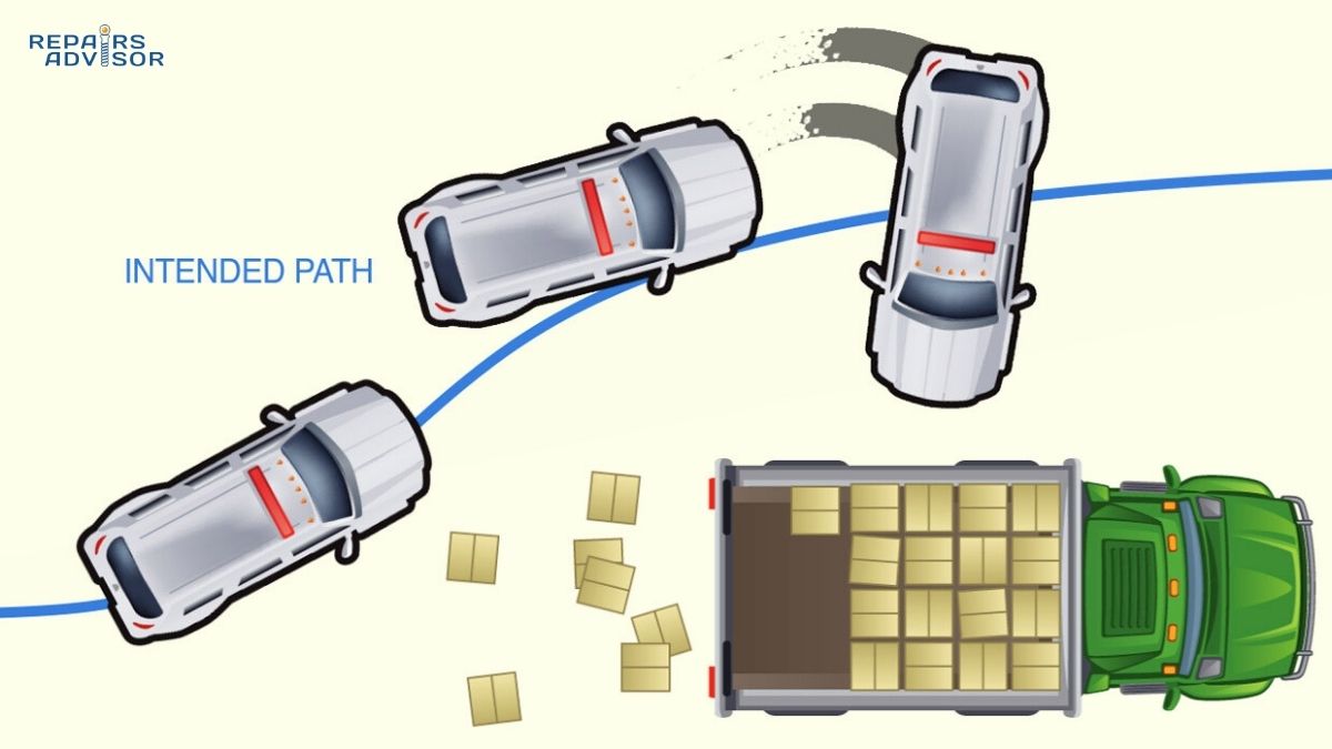
Modern drum brakes don’t operate in isolation but integrate with sophisticated electronic control systems that modulate braking force to optimize safety and performance. Anti-lock braking systems (ABS) monitor wheel speed sensors to detect impending wheel lockup during hard braking. When a rear wheel begins to lock, the ABS control module rapidly pulses hydraulic pressure to that wheel’s drum brake—up to 15 times per second—allowing the wheel to continue rotating while still providing maximum braking force just below the lockup threshold. This prevents rear-end skids and maintains vehicle stability during panic stops.
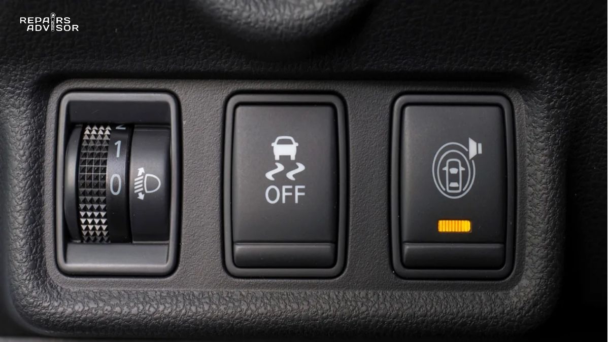
Electronic stability control (ESC) and traction control systems also command individual wheel brake applications through the hydraulic control unit. If sensors detect vehicle yaw (rotation) diverging from the driver’s steering input, ESC can apply brake force to specific wheels to generate a correcting moment that brings the vehicle back on course. This individual wheel control works seamlessly with drum brakes, though the enclosed design and slightly slower thermal response compared to disc brakes can limit sustained performance in extreme dynamic scenarios.
Hybrid and electric vehicles add another layer of integration through regenerative braking coordination. The vehicle’s control systems must seamlessly blend friction braking force from mechanical brakes with regenerative resistance from the electric motor/generators. During gentle deceleration, regenerative braking may provide 70-80% of retardation force, with drum brakes contributing minimally. As braking demand increases or battery charge reaches maximum, the system smoothly transitions to greater friction brake contribution. This careful blending maintains consistent brake pedal feel while maximizing energy recovery and extending drum brake component life through reduced duty cycles.
This complete operational sequence—from initial pedal application through hydraulic activation, self-energizing force multiplication, heat generation, and controlled release—demonstrates the sophisticated mechanical engineering embodied in what appears to be a simple braking system. Each phase builds upon the previous, creating smooth, powerful, and controllable braking performance that has served reliably for over a century of automotive evolution.
Types of Drum Brake Systems
While all drum brakes share common operating principles, significant design variations exist that optimize performance for specific vehicle applications. These different drum brake configurations manipulate how brake shoes interact with the drum and each other to achieve varying levels of braking force, directional consistency, and cost-effectiveness. Understanding these types helps explain why certain vehicles use specific drum brake designs and what performance characteristics to expect.
Leading/Trailing Shoe (Simplex) Type
The leading/trailing shoe configuration represents the most common drum brake design, found on the rear wheels of the vast majority of passenger vehicles equipped with disc/drum hybrid braking systems. This design employs a single wheel cylinder positioned at the top of the brake assembly, with two pistons that push against the top of each brake shoe simultaneously. The shoes pivot at a common anchor point positioned at the bottom of the assembly, 180 degrees opposite the wheel cylinder.
During forward braking, one shoe functions as the leading shoe—moving in the direction of drum rotation—and experiences strong positive self-energizing action. The other shoe functions as the trailing shoe—moving opposite to drum rotation—and experiences negative servo action that reduces its effective contribution. This unequal force contribution creates a brake system that provides adequate stopping power for rear-wheel applications while maintaining cost-effectiveness and simplicity.
The leading/trailing design’s primary advantage is its consistent bidirectional performance. When the vehicle reverses and braking is applied, the shoes simply reverse roles: the former trailing shoe becomes the leading shoe with positive servo action, while the former leading shoe becomes trailing. This role reversal ensures the brake generates essentially identical stopping force regardless of whether the vehicle moves forward or backward. This bidirectional consistency proves particularly valuable for parking brake applications, where the brake must hold reliably on inclines regardless of whether the vehicle faces uphill or downhill.
Installation at the rear wheels of front-wheel-drive vehicles represents the ideal application for leading/trailing drum brakes. Since front disc brakes handle 60-70% of total braking force during normal stops, the rear brakes need only contribute the remaining 30-40% of stopping power. The leading/trailing configuration provides adequate force for this secondary braking role while offering superior durability, cost-effectiveness, and parking brake integration compared to rear disc brakes. The design’s inherent balance and self-adjusting characteristics make it well-suited for vehicles where brake performance requirements are moderate but reliability and cost control are paramount.
Twin Leading Shoe (Duplex) Type
Twin leading shoe drum brakes employ two wheel cylinders—one positioned at the top of the assembly and another at the bottom—with each cylinder actuating a single brake shoe. The key distinction from leading/trailing designs is that during forward braking, both shoes function as leading shoes, each experiencing positive self-energizing action. This dual servo effect generates significantly greater braking force compared to leading/trailing designs of equivalent size, making twin leading configurations ideal for applications requiring maximum stopping power.
The mechanical arrangement positions each shoe to pivot at opposite ends of the assembly, with one wheel cylinder pushing each shoe in a direction that aligns with drum rotation during forward motion. Both shoes wedge forcefully into the drum surface under combined hydraulic and servo forces, generating braking power that can exceed dual-servo designs for forward braking applications. This superior forward stopping power made twin leading shoe brakes the preferred choice for front brakes on light-to-medium trucks before the widespread adoption of front disc brakes.
However, this performance advantage comes with a significant limitation: drastically reduced effectiveness during reverse braking. When the vehicle backs up, both shoes become trailing shoes moving against drum rotation, experiencing negative servo action simultaneously. The resulting reverse braking force may be only 30-40% of forward braking capability, creating noticeably weaker stopping power when backing. This directional sensitivity limits twin leading shoe applications to front axles where forward braking performance takes absolute priority over reverse capability.
A variant called dual twin leading shoe design incorporates double-acting wheel cylinders with pistons that can push in either direction depending on vehicle motion. This sophisticated arrangement allows both shoes to function as leading shoes regardless of travel direction, providing equally strong braking force forward or backward. The mechanical complexity and cost of this design limited its use to front brakes on medium-duty trucks and some performance applications where directional consistency was essential.
Modern applications of twin leading shoe drum brakes have largely disappeared as disc brakes became universal on front axles. The twin leading design’s performance advantages couldn’t offset its complexity, directional limitations, and inferior heat management compared to ventilated disc brakes. However, understanding this configuration remains relevant for maintenance of older vehicles and certain commercial truck applications that may still employ twin leading shoes on non-drive axles.
Duo-Servo Type
Duo-servo drum brakes represent the most powerful and mechanically sophisticated drum brake configuration, capable of generating extraordinary stopping force through an advanced self-energizing cascade effect. Unlike leading/trailing designs where shoes operate independently, duo-servo brakes mechanically link the primary (leading) and secondary (trailing) shoes through an adjustable strut or link at the bottom of the assembly. This connection allows the self-energizing force from the primary shoe to assist in applying the secondary shoe, creating a servo-on-servo amplification effect.
The operational sequence demonstrates this design’s elegance: when the wheel cylinder pushes the primary shoe outward against the rotating drum, self-energizing action wedges this shoe forcefully against the friction surface. Since the bottom of the primary shoe connects to the bottom of the secondary shoe through the floating adjuster, this wedging force transmits through the link to push the secondary shoe outward as well. The secondary shoe then generates its own self-energizing action, which feeds back through the link to further increase primary shoe force. This mutual reinforcement creates a powerful positive feedback loop—limited only by anchor pin strength and material friction coefficients—that can multiply applied force by 4-6 times or more.
This extraordinary force multiplication makes duo-servo brakes the most powerful drum brake design per unit size. Commercial vehicles requiring massive braking force for heavy loads frequently employ duo-servo drum brakes on all axles, leveraging the design’s ability to generate truck-stopping power from reasonably compact brake assemblies. The design also provides equal stopping force in both directions, as the shoe linkage allows the servo chain effect to work regardless of which shoe initiates contact during forward or reverse braking.
However, duo-servo designs exhibit critical limitations that restrict their application range. The system’s extreme sensitivity to friction coefficient means that any reduction in friction—from water contamination, glazed linings, or heat fade—causes dramatic drops in braking effectiveness. A 20% reduction in friction coefficient might reduce braking force by 40-50% in a duo-servo design, compared to 20-25% in a leading/trailing design. This sensitivity makes duo-servo brakes less forgiving of worn friction material, contamination, or overheating.
The mechanical complexity of duo-servo systems also increases service difficulty and requires precise adjustment. The floating link between shoes must be set to exact length to ensure both shoes contact the drum simultaneously and share load appropriately. Improper adjustment can cause one shoe to do most of the work while the other barely contacts the drum, negating the servo amplification advantage. Many technicians find duo-servo brakes more challenging to service correctly compared to simpler leading/trailing designs.
Modern passenger vehicles rarely use duo-servo drum brakes, as the design’s advantages don’t justify its complexity for rear-brake applications where disc brakes already handle primary stopping duties. However, duo-servo designs remain common on heavy commercial trucks, trailers, and some performance applications where maximum braking force per unit weight and cost are essential. Understanding duo-servo operation is critical for anyone servicing commercial vehicle brakes or maintaining older performance vehicles equipped with this powerful but demanding brake design.
Drum Brakes vs. Disc Brakes: Understanding the Trade-offs
The disc versus drum brake debate has persisted throughout automotive history, with each technology offering distinct advantages that make it optimal for specific applications. Rather than one being universally superior, modern brake system design strategically deploys each technology where its strengths provide maximum benefit. Understanding these trade-offs helps explain why most vehicles combine front disc brakes with rear drum brakes rather than using one technology exclusively.
Drum Brake Advantages
Cost-effectiveness stands as drum brakes’ most compelling advantage, with complete drum brake assemblies typically costing 40-60% less to manufacture than equivalent disc brake systems. This cost advantage stems from simpler construction requiring no calipers, fewer precision-machined surfaces, less expensive friction materials, and straightforward mounting that doesn’t demand tight tolerances. For automakers producing millions of vehicles annually, specifying drum brakes for rear wheels where ultimate performance isn’t required saves substantial costs without compromising safety. This economic reality explains why even premium vehicles often retain rear drum brakes despite front disc brakes.
Self-energizing action provides drum brakes with a fundamental mechanical advantage that disc brakes cannot match. The servo effect multiplies applied force by 2-3 times beyond hydraulic pressure alone, allowing compact, lightweight drum brake assemblies to generate stopping force comparable to much larger disc brake systems. This force multiplication proves particularly valuable for parking brake applications, where mechanical cable tension can generate sufficient holding power to secure vehicles on steep inclines—a feat difficult to achieve with disc brake parking mechanisms that lack servo assistance.
Durability and longevity favor drum brakes significantly in appropriate applications. The enclosed design protects all internal components from road salt, water spray, mud, and debris that rapidly corrode exposed disc brake components. This environmental protection, combined with larger friction contact area that distributes wear across greater surface, enables drum brake shoes to last 250,000-300,000 kilometers before requiring replacement—often double or triple the service life of disc brake pads in similar applications. Lower maintenance frequency translates to reduced lifetime ownership costs and fewer service appointments.
Parking brake integration represents another clear drum brake advantage. The mechanical lever-and-cable parking brake system mounts directly within the drum brake assembly, using the same shoes and friction surfaces as the hydraulic service brakes. This shared-component approach provides reliable, fail-safe parking brake functionality at minimal additional cost or complexity. Disc brake parking mechanisms typically require separate mini-drum systems integrated into the rotor hat, or complex screw-actuated calipers that add cost and potential failure points.
Drum Brake Limitations
Heat dissipation stands as drum brakes’ most significant weakness, with the enclosed design severely limiting cooling capacity compared to ventilated disc brakes. Air cannot flow freely across the friction surfaces to carry away heat, forcing drums to rely on conduction through the drum casting to the outer surface, then radiation and convection to surrounding air. During sustained heavy braking—such as descending mountain grades or repeated high-speed stops—drum temperatures can rise rapidly to 600-800°F or higher, approaching the thermal limits where friction materials begin to fade and lose effectiveness.
Brake fade under extreme conditions occurs more readily with drum brakes than disc brakes due to inferior heat management. As drum temperature rises, friction coefficient drops and pedal travel increases as components expand thermally. Drivers must push the pedal harder and farther to maintain braking force, potentially reaching the floor during extreme fade. While modern friction materials resist fade better than historical organic compounds, the fundamental heat dissipation limitation means drum brakes reach fade threshold sooner than disc brakes during demanding use.
Mechanical complexity and service difficulty exceed disc brakes despite drum brakes’ simpler external appearance. A typical drum brake assembly contains 15-20 individual components—springs, adjusters, hardware—that must be disassembled, inspected, and correctly reassembled during service. Spring removal and installation requires special tools and technique to avoid injury or incorrect assembly. Automatic adjusters can seize or malfunction, requiring skilled diagnosis. In contrast, disc brake service involves removing calipers, replacing pads, and reassembly—typically a simpler procedure requiring fewer special tools.
Water sensitivity affects drum brakes more than disc brakes, as the enclosed design can trap water inside the drum after driving through deep puddles or heavy rain. Water between shoes and drum dramatically reduces friction coefficient temporarily, causing temporarily weak or uneven braking until repeated brake applications evaporate the moisture. Disc brakes experience similar initial water contamination, but the exposed design and centrifugal force of the spinning rotor quickly expel water. The brake pads also act like squeegees, wiping water from the rotor surface after only 1-2 applications.
Weight penalties accumulate with drum brakes due to the substantial cast iron drum mass required for structural strength and thermal capacity. A typical drum brake assembly weighs 15-20 pounds more than an equivalent disc brake, adding unsprung mass that degrades ride quality and handling response. This weight disadvantage is one reason performance vehicles universally employ four-wheel disc brakes despite the cost premium—reducing unsprung weight improves suspension effectiveness and dynamic response.
Modern Hybrid Systems: Optimizing Both Technologies
Contemporary brake system design strategically combines technologies to leverage each design’s strengths while minimizing weaknesses. The nearly universal configuration employs ventilated disc brakes at the front wheels—where 60-70% of braking force is needed and heat generation is most severe—paired with drum brakes at the rear wheels that handle remaining braking force and parking brake duties. This hybrid approach optimizes performance, cost, and reliability.
Front disc brakes provide superior stopping power and heat management exactly where it’s needed most. During braking, weight transfer loads the front suspension and unloads the rear, concentrating braking force demand at the front wheels. Ventilated disc brake rotors dissipate heat efficiently through internal air passages and exposed surfaces, maintaining consistent performance during sustained hard braking. Front disc brakes also reduce unsprung weight compared to drums, improving steering feel and suspension response.
Rear drum brakes contribute adequate stopping force for the secondary braking role while offering significant advantages for rear-wheel applications. Since weight transfer during braking reduces rear wheel load, less braking force is needed at the rear to avoid premature rear wheel lockup. Drum brakes easily provide the required rear braking force while offering superior durability, weather protection, and integrated parking brake functionality at lower cost than rear disc brakes. The enclosed design’s heat retention disadvantage matters less at the rear wheels where heat generation is lower.
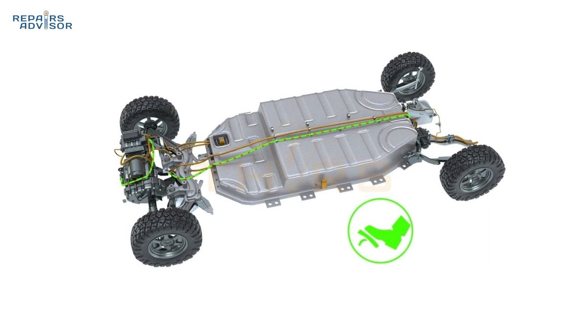
Electric and hybrid vehicles represent an emerging application where rear drum brakes offer unexpected advantages. These vehicles rely heavily on regenerative braking for normal deceleration, with friction brakes providing only supplemental and emergency stopping force. Since mechanical brake usage is dramatically reduced, drum brake durability perfectly matches the duty cycle. The Toyota Prius, Volkswagen ID.4, and many other hybrids and EVs employ rear drum brakes specifically because the enclosed design’s longevity and low maintenance requirements suit reduced-duty-cycle applications. These vehicles also benefit from reduced particulate matter emissions compared to disc brakes, as wear particles remain trapped within the drum rather than dispersing into the environment.
Understanding the complementary nature of disc and drum brake technologies explains modern brake system architecture. Rather than representing obsolete versus advanced technology, drum brakes continue fulfilling specific roles where their advantages outweigh limitations. The optimal system uses each technology strategically: disc brakes where ultimate performance and heat management matter most, drum brakes where durability, cost-effectiveness, and parking brake integration provide greater value.
Drum Brake Location and Access Guide
Drum brakes mount at each rear wheel on vehicles equipped with hybrid disc/drum braking systems, positioned between the wheel and axle or suspension components. Understanding where drum brakes are located, how to access them, and what tools are required for inspection helps DIY mechanics assess brake condition and determine when professional service may be necessary. This section provides practical guidance for identifying, accessing, and evaluating drum brake assemblies safely.
Visual Identification and Component Recognition
With the wheel installed, drum brakes remain hidden from view behind the wheel and tire assembly. Unlike disc brakes where rotors and calipers are visible through wheel spokes, drum brake assemblies present only the outer surface of the brake drum—a cylindrical casting approximately 9-11 inches in diameter that appears as part of the hub assembly. The drum’s outer surface is typically unpainted cast iron with a natural gray-brown patina, though some vehicles use drums with protective coating that may be silver, black, or painted to match vehicle color.
Maximum allowable drum diameter specifications are permanently stamped or cast into the drum’s outer edge, visible once the wheel is removed. This stamping typically reads “MAX DIAM 10.040 IN” or similar, indicating the maximum internal diameter beyond which the drum must be replaced. This specification provides critical information for determining drum serviceability during inspection. Adjacent to the diameter specification, you’ll often find date codes or part numbers that identify the drum’s manufacture date and OEM specifications.
Removing the wheel reveals the complete drum assembly bolted to the wheel hub via the same lug studs that secure the wheel. Depending on vehicle design, the drum may be hubbed (with wheel bearings integrated into the drum casting) or hubless/floating (sliding over a separate hub assembly). Hubbed drums were common on older rear-wheel-drive vehicles, while modern front-wheel-drive vehicles almost universally use floating drums. The distinction matters for service procedures, as hubbed drums require bearing service during drum removal while floating drums simply slide off the hub.
The backing plate becomes visible behind the drum as a dark steel disc, typically 12-14 inches in diameter, bolted to the axle or suspension. This plate provides the mounting surface for all internal brake components. Several features help identify components: the wheel cylinder appears as a small aluminum or steel housing at the top of the assembly, often with a rubber brake line connected; the access hole (if present) allows inspection of lining thickness without complete disassembly; and the parking brake cable routing can be traced from its backing plate entry point.
Access Requirements and Safety Preparations
Accessing drum brakes for inspection requires raising the vehicle and removing the wheels, following proper safety protocols to prevent injury or vehicle damage. The minimum equipment includes a quality hydraulic floor jack rated for vehicle weight, jack stands with capacity exceeding vehicle weight, a lug wrench or impact wrench, and wheel chocks. Additional useful tools include a rubber mallet for drum removal, brake parts cleaner spray, shop rags, and personal protective equipment.
Safety preparations begin with parking the vehicle on level, solid ground with the transmission in park (automatic) or first gear (manual). Apply the parking brake firmly if inspecting front drum brakes, but do NOT engage parking brake when inspecting rear drum brakes—engaging rear parking brakes prevents drum removal. Position wheel chocks in front of and behind wheels that will remain on the ground during the procedure. Consult the vehicle owner’s manual to identify proper jacking points, as improper jack placement can damage body panels, suspension components, or chassis structures.
Raise the vehicle with the floor jack positioned at the designated jacking point, lifting until the tire clears the ground by 2-3 inches. Immediately place jack stands under designated support points before beginning any work. Lower the vehicle onto the jack stands until weight transfers fully, then shake the vehicle to ensure stable support. Never work under a vehicle supported only by a jack, as hydraulic jack failure can cause catastrophic crushing injuries. The jack should remain in position as backup support but not bearing vehicle weight.
Personal protective equipment is essential for brake work due to friction material dust that may contain hazardous substances. Wear safety glasses to protect eyes from debris and brake cleaner spray. Use nitrile gloves to protect hands from brake fluid, which damages paint and skin. Most importantly, wear a dust mask or respirator when working around drum brakes, as friction material dust—while no longer containing asbestos in modern vehicles—still presents respiratory irritation risk. Never blow brake dust away with compressed air, as this creates dangerous airborne particles.
Professional Service Indicators and DIY Boundaries
Intermediate DIY mechanics can safely perform visual drum brake inspections, assess component condition, and make informed decisions about when professional service is required. The skill boundary lies between inspection and actual service work: while examination and evaluation fall within DIY capability for those with mechanical aptitude, brake shoe replacement, wheel cylinder service, and spring hardware work require greater expertise, specialized tools, and thorough understanding of proper procedures.
Indicators that suggest professional service include any brake fluid leaks around the wheel cylinder, evidenced by dark, oily residue on the backing plate or drum inner surface. Wheel cylinder leaks indicate failed piston cups that allow hydraulic fluid to escape, requiring cylinder replacement or rebuild. Attempting to drive with leaking wheel cylinders risks complete brake failure if fluid level drops sufficiently, making this a safety-critical issue requiring immediate professional attention.
Uneven brake shoe wear patterns—where one shoe shows significantly greater wear than its partner—indicate possible seized wheel cylinder pistons, contaminated friction surfaces, or worn automatic adjusters. While observing this condition is straightforward, diagnosing and correcting the root cause requires understanding drum brake mechanics and access to proper service information. Professional technicians can identify whether wheel cylinder replacement, adjuster service, or other repairs are necessary to restore proper operation.
Damaged or broken return springs and hold-down hardware present serious safety hazards that mandate immediate professional service. These springs operate under high tension and can cause injury if they suddenly release during improper removal attempts. Worn or heat-damaged springs also compromise brake performance, potentially causing brake drag, uneven shoe application, or reduced retraction that leads to overheating. Professional brake technicians have specialized spring tools and training to service hardware safely and correctly.
Excessive drum wear beyond maximum diameter specifications requires drum replacement, a service best left to professionals who can properly measure drum diameter with specialized micrometers, determine if drums can be machined or must be replaced, and ensure new drums are correctly installed and adjusted. Contaminated friction surfaces—evidenced by oil or grease on brake shoes or drum inner surface—typically indicate leaking axle seals or wheel bearings that require professional diagnosis and repair beyond simple brake service.
First-time DIY mechanics should strongly consider professional service or supervised learning when attempting drum brake work. While inspection builds knowledge and understanding, actual service work involves dozens of small springs, clips, and adjusters that must be removed and reinstalled in exact positions using proper techniques. Working alongside an experienced technician or taking advantage of hands-on training courses helps develop the skills and confidence necessary for safe, successful drum brake service.
Understanding these access requirements and recognizing professional service indicators helps DIY mechanics make informed decisions about brake maintenance. Visual inspection provides valuable information about brake condition and remaining service life, while recognizing the boundaries of DIY capability ensures safety-critical brake work receives appropriate professional attention when needed.
Maintenance, Inspection, and Troubleshooting
Regular drum brake maintenance extends component life, ensures consistent performance, and prevents small issues from developing into safety-critical failures. While drum brakes require less frequent service than disc brakes due to their enclosed design and longer-wearing friction materials, periodic inspection and preventive maintenance remain essential for safe vehicle operation. This section provides practical guidance for maintaining drum brakes, recognizing wear indicators, diagnosing common problems, and determining when professional service is necessary.
Regular Inspection Schedule and Best Practices
Drum brake inspection should occur every 20,000-40,000 miles as part of routine tire rotation service, providing opportunity to assess brake shoe wear, hardware condition, and overall system health before problems develop. This inspection frequency aligns with typical tire rotation intervals, making it convenient to evaluate brakes whenever wheels are removed for tire service. More frequent inspection may be warranted for vehicles subjected to severe duty cycles—frequent trailer towing, mountainous terrain driving, or commercial use—where brake system demands exceed normal passenger car usage.
Brake fluid condition and level require separate attention every six months regardless of mileage. Glycol-based brake fluids are hygroscopic, absorbing moisture from the atmosphere over time through microscopic pores in rubber hoses and seals. Moisture contamination lowers brake fluid boiling point and promotes internal corrosion of wheel cylinders, master cylinders, and brake lines. Checking fluid level in the master cylinder reservoir takes only moments and provides early warning of leaks or excessive wear. Dark, cloudy, or discolored fluid indicates contamination requiring immediate replacement.
Complete brake fluid replacement every 24 months (or per manufacturer specifications) represents essential preventive maintenance that many vehicle owners overlook. Fresh fluid with proper boiling point prevents vapor lock during hard braking and protects system components from corrosion. The modest cost of fluid service—typically $80-120 at professional shops—prevents expensive repairs from corroded wheel cylinders or master cylinders that can develop when fluid maintenance is neglected. DIY mechanics with proper bleeding equipment and procedures can perform this service at minimal cost.
During each inspection, monitor for warning signs that may indicate developing problems requiring attention before they become safety issues. Unusual noises during braking—squealing, grinding, or scraping sounds—suggest worn friction material, damaged hardware, or debris contamination. Vibrations or pulsations through the brake pedal indicate distorted drums or uneven shoe wear. Vehicle pulling to one side during braking points to uneven brake force between left and right wheels, possibly from contaminated shoes, malfunctioning wheel cylinder, or seized adjuster.
Brake Shoe Wear Assessment and Replacement Criteria
Evaluating brake shoe condition requires removing the drum to directly inspect friction material thickness, wear patterns, and overall shoe condition. Modern drum brakes typically lack the external wear indicators common on disc brake pads, making visual inspection the only reliable method for assessing remaining lining life. Professional shops often include drum inspection during tire service, but DIY mechanics can learn to perform this inspection with proper tools and safety precautions.
Friction material thickness provides the primary indicator for determining shoe replacement necessity. Riveted brake shoes—where friction material attaches to the shoe with metal rivets—must be replaced when lining material wears to within 1/32 inch (0.8 millimeters) of any rivet head. Continuing to use shoes beyond this point allows rivets to contact the drum, causing severe scoring damage that requires expensive drum replacement. Bonded brake shoes—where friction material adheres with high-temperature adhesive—require replacement when lining thickness reaches 1/16 inch (1.6 millimeters), as thinner material risks adhesive bond failure or backing plate contact.
Uneven wear patterns between primary and secondary shoes, or between left and right brake assemblies, indicate potential problems requiring diagnosis beyond simple shoe replacement. The primary (leading) shoe typically shows somewhat greater wear than the secondary shoe due to self-energizing action, but dramatic differences suggest malfunctioning wheel cylinder pistons, contaminated friction material, or seized automatic adjusters. Shoes should wear relatively evenly across their length; wear concentrated at one end indicates improper adjustment, distorted drums, or worn pivot/anchor components.
Glazed friction material surfaces appear shiny and smooth rather than showing the normal slightly rough texture. Glazing occurs when brake shoes experience excessive heat without sufficient cooling, causing friction material binders to migrate to the surface and form a hardened layer. This glazed surface dramatically reduces friction coefficient, requiring increased pedal pressure to achieve normal stopping force. Glazing typically results from driving with dragging brakes, extended downhill braking, or operating with severely overloaded vehicle. Glazed shoes must be replaced, as the glazed layer cannot be effectively removed and will continue exhibiting poor performance.
Oil or grease contamination of friction material—indicated by dark, shiny areas or visible fluid on shoe surfaces—necessitates immediate shoe replacement plus diagnosis and repair of the contamination source. Common causes include leaking axle seals, leaking wheel bearings (on hubbed drums), or brake fluid leaking from wheel cylinder. Contaminated shoes cannot be cleaned or salvaged, as petroleum products penetrate friction material and permanently destroy its friction characteristics. Simply replacing contaminated shoes without addressing the leak source will result in rapid contamination of new shoes.
Drum Condition Evaluation and Service Limits
Brake drum condition directly affects braking performance, safety, and component longevity, making thorough drum inspection essential during any brake service. Three primary measurements determine drum serviceability: internal diameter, out-of-round condition, and surface condition. Professional shops use precision drum micrometers or specialized brake lathes with measurement capabilities, while DIY mechanics can perform basic visual inspection to identify obvious problems requiring professional attention.
Maximum internal diameter specifications stamped on each drum establish the absolute limit beyond which the drum must be replaced regardless of apparent condition. This specification accounts for the drum’s structural strength requirements and heat dissipation capacity, both of which diminish as wall thickness decreases. Typical specifications allow drums to wear 0.060 inches beyond original diameter before requiring replacement, or 0.080 inches for drums that have been machined once. Exceeding these limits risks drum failure under braking loads or extreme overheating that could cause catastrophic brake failure.
Measuring drum diameter requires taking multiple readings at 90-degree intervals around the circumference, both horizontally and vertically, to detect out-of-round conditions. Drums should maintain cylindrical shape within 0.005 inches around their entire circumference. Greater variation indicates distortion from overheating, improper installation, or bearing problems (hubbed drums). Out-of-round drums cause pulsating brake pedal feel and uneven shoe wear as shoes alternately approach and recede from the drum surface during rotation. Drums exhibiting excessive out-of-round condition must be machined to restore cylindrical geometry or replaced if they exceed maximum diameter specifications.
Surface condition assessment examines the drum’s friction surface for scoring, heat checking, hot spots, and other damage that affects braking performance. Fine heat checking—small surface cracks appearing as a network of tiny lines—is normal on drums with extended service life and generally doesn’t require correction unless cracks exceed 0.015 inches in depth. However, localized heat checking concentrated in specific areas indicates overheating from uneven shoe contact, contaminated friction material, or dragging brakes. Deep cracks, especially those extending through the drum wall, mandate immediate drum replacement as structural failure risk becomes unacceptable.
Scoring—grooves or scratches in the friction surface—results from abrasive contamination, severely worn shoes with exposed rivets or backing plates, or debris trapped between shoe and drum. Light scoring less than 0.015 inches deep can often be removed by drum machining, restoring smooth friction surface. Deep scoring requires drum replacement, as excessive material removal would thin the drum beyond safe limits. Blue discoloration or hot spotting indicates extreme overheating that may have altered the drum’s metallurgical properties, potentially causing distortion or cracking. Drums showing significant discoloration should be replaced rather than machined.
Common Problems: Diagnosis and Resolution
Squealing or grinding noises during brake application typically indicate worn brake shoes requiring replacement, though other causes can produce similar symptoms. High-pitched squealing often results from worn shoe linings approaching their service limit, with wear indicators (if equipped) or backing plates beginning to contact the drum. Grinding noises suggest metal-to-metal contact between backing plates and drum, indicating shoes have exceeded their service life and likely caused drum damage requiring replacement. Unusual rattling or clicking may point to broken or loose return springs and hold-down hardware that require professional service.
Reduced braking performance manifests as longer stopping distances, increased pedal effort required for normal stops, or brake fade during extended use. Multiple root causes can create these symptoms, requiring systematic diagnosis. Air in the hydraulic system—typically from low fluid level, recent component replacement without proper bleeding, or leaking wheel cylinders—produces spongy pedal feel and reduced braking force. Bleeding the brake system purges air and restores solid hydraulic coupling, though finding and repairing leak sources is essential for permanent correction.
Brake fade during sustained braking results from drum overheating that reduces friction coefficient and causes pedal travel increase as components thermally expand. Descending long grades, repeated high-speed stops, or operating with severely overloaded vehicle can generate heat faster than drums dissipate it, leading to fade. Drivers experiencing fade should downshift to lower gears for engine braking and avoid continuous brake application, instead using intermittent braking that allows cooling between applications. Severely overheated drums may require replacement if heat damage has distorted them or altered their metallurgical properties.
Glazed friction material from previous overheating episodes continues causing reduced braking performance even after drums cool, as the hardened friction surface layer provides poor friction characteristics. The only effective correction is replacing brake shoes with fresh friction material, though investigating and correcting the overheating cause prevents rapid reglazng of new shoes. Common overheating causes include dragging brakes from incomplete shoe retraction, inadequate brake force distribution (rear brakes doing excessive work), or driver technique issues on vehicles frequently operated in mountainous terrain.
Vehicle pulling to one side during braking indicates unequal braking force between left and right wheels, creating steering imbalance that requires hands-on steering correction. This condition presents serious safety concerns, as emergency braking can cause severe pull that drivers may be unable to control. Potential causes include contaminated brake shoes on one side (oil or grease), malfunctioning wheel cylinder with seized piston, seized automatic adjuster creating different shoe-to-drum clearances side-to-side, or significantly different drum diameters from uneven wear or previous machining.
Diagnosing pulling requires comparing brake condition between left and right sides, examining shoe wear patterns, checking wheel cylinder operation, and verifying adjuster function. Professional diagnostic equipment can measure actual braking force at each wheel to quantify imbalance. Correction typically involves identifying and repairing the root cause—replacing contaminated shoes and sealing leak sources, rebuilding or replacing malfunctioning wheel cylinders, or servicing seized adjusters—then ensuring both sides have matching new components properly adjusted for equal performance.
Vibration or pulsation through the brake pedal or steering wheel during brake application points to distorted brake drums that have lost their cylindrical shape. This distortion causes shoe-to-drum gap to vary as the drum rotates, creating pulsating brake force that transmits through the suspension as vibration. Out-of-round drums result from severe overheating, uneven torque when installing wheel lug nuts, or worn wheel bearings (on hubbed drum vehicles). Correction requires drum machining to restore cylindrical geometry or drum replacement if distortion is severe or drums exceed maximum diameter specifications.
Break-In Procedures for New Components
New brake shoes require a proper break-in period of 300-500 kilometers to achieve optimal performance and longevity. During this initial period, the friction material surface must conform to the drum’s contours while microscopic high spots on both surfaces gradually wear to create maximum contact area. Rushing this break-in through aggressive braking can glaze friction material or generate excessive heat before proper seating occurs, permanently degrading performance. Patient break-in delivers full braking capability and maximum component life.
Break-in technique emphasizes gentle to moderate braking applications rather than aggressive stops. Use light to medium pedal pressure for the first few dozen stops, avoiding hard braking except in emergencies. This gentle approach allows friction material and drum surfaces to gradually mate without generating excessive heat. After approximately 200 kilometers of this gentle use, gradually increase braking intensity over the next 200-300 kilometers, working up to normal driving conditions. This progressive approach ensures optimal friction material seating and heat treatment.
Avoid sudden hard braking during the entire break-in period, as high initial temperatures can glaze new friction material before proper seating occurs. Emergency stops remain acceptable if safety demands—brake performance even during break-in should provide adequate stopping force—but deliberately testing maximum braking capability should wait until break-in completes. Similarly, avoid extended downhill descents or repeated stops that might overheat new shoes before they’ve properly seated to the drums.
Do not conduct official brake performance tests—such as required during vehicle safety inspections (MOT, TÜV, etc.)—until break-in completes, as braking force may measure slightly below normal during the seating period. Most inspection facilities will recognize recently replaced brakes and may retest after appropriate break-in mileage. Professional installers typically document installation date and mileage, recommending customers return for inspection after break-in completion if initial measurements fall slightly below inspection standards.
Understanding these maintenance requirements, inspection criteria, and troubleshooting approaches empowers vehicle owners to maintain drum brakes proactively, recognize developing problems early, and make informed decisions about when professional service is necessary. While drum brakes are durable and long-lived when properly maintained, neglecting regular inspection and fluid service can lead to component failures that compromise safety and require expensive repairs beyond simple brake shoe replacement.
Conclusion: The Enduring Value of Drum Brake Technology
Drum brakes continue serving as essential safety components on millions of vehicles worldwide, providing cost-effective, durable braking performance that meets the demanding requirements of modern automotive applications. Their elegant mechanical design leverages self-energizing action to multiply braking force, creating powerful stopping capability from compact assemblies that integrate seamlessly with parking brake systems. Understanding how drum brakes work—from component construction through hydraulic activation to the physics of self-energizing operation—helps vehicle owners maintain these systems properly and recognize when service is necessary.
The strategic combination of front disc brakes with rear drum brakes represents thoughtful engineering that optimizes each technology’s strengths while minimizing weaknesses. Disc brakes deliver superior stopping power and heat management at the front wheels where braking demands are greatest, while drum brakes provide adequate rear braking force with exceptional durability, weather protection, and parking brake integration at lower cost. This hybrid approach appears in the vast majority of passenger vehicles for sound technical and economic reasons that balance performance, safety, reliability, and cost across the vehicle’s service life.
Regular inspection and maintenance extend drum brake component life and ensure consistent safety performance. Checking brake fluid condition every six months, replacing fluid every 24 months, and inspecting brake shoes during tire rotation intervals of 20,000-40,000 miles provides adequate monitoring without excessive maintenance burden. Recognizing warning signs—unusual noises, vibrations, vehicle pulling, or reduced braking effectiveness—allows early intervention before minor issues develop into safety-critical failures requiring extensive repairs. Proper diagnosis of common problems prevents unnecessary component replacement and ensures repairs address root causes rather than just symptoms.
When Professional Consultation is Essential
While intermediate DIY mechanics can safely perform visual drum brake inspections and assess component condition, actual service work falls into professional territory for most vehicle owners. Hydraulic system repairs—wheel cylinder replacement, brake line service, or system bleeding—require specialized tools, proper procedures, and thorough understanding of safety-critical brake system requirements. Attempting these repairs without adequate knowledge, tools, and experience risks brake failure that could cause accidents or injuries.
Severe heat damage to drums or friction materials—evidenced by cracked drums, extreme discoloration, or glazed shoe surfaces—mandates professional evaluation and repair. Overheating can alter drum metallurgical properties in ways that visual inspection doesn’t reveal, potentially leading to sudden structural failure under subsequent heavy braking. Professional technicians have experience recognizing heat damage severity and access to precision measurement equipment that determines whether components can be safely machined or must be replaced.
First-time brake service represents another scenario where professional guidance provides immense value. Drum brake assemblies contain numerous springs, adjusters, and hardware pieces that must be removed and reinstalled in specific sequences using proper techniques. Working alongside an experienced technician or seeking professional training helps develop the skills and confidence necessary for successful brake service. Many community colleges and vocational schools offer hands-on automotive courses that teach proper brake service procedures in supervised environments where mistakes don’t create safety hazards.
Brake adjustment problems—persistent brake drag, inadequate braking force despite new components, or brake pedal that travels excessively far—often indicate issues beyond simple shoe wear requiring professional diagnostic expertise. Modern vehicles integrate drum brakes with electronic systems including ABS, traction control, and electronic stability control, creating complexity that extends beyond mechanical brake assembly work. Specialized diagnostic equipment and training helps professionals identify whether problems stem from mechanical brake components, hydraulic system issues, or electronic control system malfunctions.
Final Safety Reminders
Brake system integrity directly impacts vehicle safety and accident prevention capability. Properly functioning brakes can mean the difference between safely stopping before an obstacle and causing a collision that injures occupants or bystanders. This safety criticality demands that all brake work—whether DIY or professional—follows proper procedures, uses quality replacement components, and includes thorough testing before returning the vehicle to service. Cutting corners on brake maintenance or service quality is never acceptable.
If uncertainty exists about brake condition, repair procedures, or the appropriate course of action for addressing brake problems, consult a qualified automotive technician. Professional mechanics have training, experience, and diagnostic capabilities that enable accurate problem identification and proper repair. The modest cost of professional service provides tremendous value when compared to potential consequences of brake failure from improper repairs or ignored warning signs. Brake service is not an area where trial-and-error DIY experimentation should occur.
Vehicle owners should never ignore brake warning signs or defer necessary brake service due to cost concerns or inconvenience. Brake problems rarely improve on their own and typically worsen progressively until component failure occurs. What might have been a straightforward brake shoe replacement can escalate to damaged drums, seized wheel cylinders, and damaged brake lines if neglected too long. Addressing brake issues promptly when they’re identified saves money through less extensive repairs while maintaining the safety performance that protects vehicle occupants and other road users.
Understanding drum brake operation, maintenance requirements, and limitations empowers informed decision-making about brake system care. Whether you maintain your own vehicle or rely on professional service, this knowledge helps you recognize when brake attention is needed, communicate effectively with service providers, and appreciate the sophisticated engineering embodied in these time-tested braking systems. Drum brakes have reliably stopped vehicles for over a century of automotive evolution and continue serving this essential safety function on modern vehicles, testament to the enduring value of this elegant mechanical design.