The camshaft is one of the most critical components for engine performance, acting as the precise conductor that orchestrates when your engine’s valves open and close. Understanding how camshafts work helps intermediate DIY enthusiasts diagnose timing issues, while professionals can leverage this knowledge for performance optimization and complex timing system repairs. Even beginners benefit from understanding this fundamental component that directly affects engine power, efficiency, and emissions.
Safety Note: Camshaft work involves precise timing relationships. Beginners should focus on understanding the principles rather than attempting repairs. Intermediate enthusiasts can handle basic inspection and timing verification. Complex camshaft replacement or timing adjustments should be performed by qualified professionals due to potential engine damage from timing errors.
Why Camshafts Are Critical for Engine Performance
The camshaft serves as the engine’s breathing controller, determining exactly when intake and exhaust valves open and close during each combustion cycle. This precise timing control directly impacts engine performance, fuel efficiency, emissions, and overall power delivery. Without proper camshaft operation, engines cannot maintain the precise valve timing necessary for optimal combustion.
For Intermediate DIY Enthusiasts: The camshaft’s timing relationship with the crankshaft must maintain perfect synchronization – typically at a 2:1 ratio where the camshaft rotates once for every two crankshaft rotations. This timing relationship affects valve overlap, intake efficiency, and exhaust scavenging. Understanding these relationships helps diagnose performance issues like rough idle, power loss, or unusual engine noises.
For Professional Mechanics: Camshaft profiles directly influence volumetric efficiency, compression ratio dynamics, and power band characteristics. Modern variable valve timing systems use camshaft position feedback to optimize timing based on engine load and RPM conditions. Professional diagnostics require understanding how camshaft timing affects engine management system parameters and emissions compliance.
For Beginners: Think of the camshaft as the engine’s conductor – just as a conductor controls when different instruments play in an orchestra, the camshaft controls when valves open to let air in and exhaust out. This timing must be perfect for the engine to run smoothly and efficiently.
The camshaft’s lobes are specifically designed with unique profiles that determine valve lift, duration, and timing characteristics. These profiles directly influence engine performance characteristics from idle smoothness to peak power delivery.
Early Warning Signs and Symptoms
Engine performance degradation often provides the first clues that your camshaft may be developing problems, though these symptoms can be subtle and easily attributed to other causes. Power loss typically develops gradually, with drivers first noticing reduced acceleration response or difficulty maintaining highway speeds during hills or headwinds. The engine may feel like it’s “holding back” during acceleration, particularly at higher RPMs where proper valve timing becomes more critical for optimal breathing. This occurs because worn cam lobes can’t open valves to their full extent or for the proper duration, reducing the engine’s ability to intake fresh air-fuel mixture and expel exhaust gases efficiently.
Fuel economy changes often accompany performance issues but may be the only noticeable symptom in early-stage camshaft wear. When valves don’t open and close with optimal timing, combustion efficiency suffers, requiring more fuel to produce the same power output. Drivers may notice they’re filling up more frequently or that their usual driving routes require more fuel than expected. This symptom is particularly insidious because it develops slowly, and many drivers adapt their expectations without realizing an underlying mechanical problem exists.
Audible symptoms provide some of the most reliable early indicators of camshaft problems, though they require careful listening to distinguish from other engine noises. The characteristic “ticking” or “tapping” sound associated with camshaft wear typically increases in frequency with engine RPM and is most noticeable from the top of the engine near the valve cover. This noise results from increased clearances between worn cam lobes and their followers, creating impact sounds as the components make contact. Cold engine operation often makes these noises more pronounced, as oil viscosity changes and clearances increase with lower temperatures.
The location and characteristics of these noises provide diagnostic clues about the severity and specific nature of camshaft problems. Rhythmic ticking that follows engine RPM precisely suggests cam lobe wear, while irregular or intermittent noises might indicate more complex timing system issues. Some drivers describe the sound as similar to a playing card in bicycle spokes—a rapid clicking that varies with engine speed. Professional technicians often use automotive stethoscopes to isolate these sounds and determine their exact source.
Visual indicators can sometimes be observed without engine disassembly, particularly changes in exhaust smoke patterns that suggest combustion irregularities. Improper valve timing from camshaft wear can cause incomplete combustion, resulting in black smoke from rich running conditions or blue smoke from oil consumption due to poor valve sealing. Modern engines with sophisticated emission controls may trigger check engine lights or fail emission tests due to the combustion irregularities caused by camshaft problems.
Engine behavior changes during idling and starting provide additional diagnostic information about camshaft condition. Rough idle quality, irregular RPM fluctuations, or difficulty maintaining stable idle speed can all result from inconsistent valve timing caused by camshaft wear. Starting difficulties, particularly when the engine cranks normally but struggles to fire, may indicate that valve timing has shifted enough to affect combustion quality. In severe cases, engines may stall unexpectedly or refuse to start at all, though this typically indicates advanced camshaft wear requiring immediate attention.
Understanding these engine performance diagnostic indicators helps differentiate camshaft problems from other potential causes like fuel system issues, ignition problems, or sensor failures. The key is recognizing patterns of symptoms that point specifically to valve timing irregularities rather than fuel delivery or spark timing problems.
Visual Inspection Techniques
Professional camshaft inspection begins with oil analysis—one of the most revealing early detection methods available to both technicians and informed vehicle owners. Metal contamination in engine oil provides definitive evidence of internal wear before external symptoms become obvious. During oil changes, experienced technicians examine the oil filter media for metal particles, looking specifically for ferrous (magnetic) particles that indicate camshaft and lifter wear. A simple magnetic drain plug can capture these particles, while oil analysis services can quantify metal content and identify specific wear sources.
The appearance and characteristics of metal contamination tell a detailed story about camshaft condition. Fresh, shiny metal particles indicate active wear, while older, oxidized particles suggest wear that occurred in previous service intervals. Large particles or chunks indicate severe wear or impending failure, while fine particles might represent normal wear or early-stage problems. Professional oil analysis can differentiate between iron particles from camshaft wear, aluminum from bearing wear, and copper from bushing wear, providing a comprehensive picture of internal engine condition.
Direct visual inspection requires valve cover removal but provides the most definitive assessment of camshaft condition. Professional technicians look for specific wear patterns on cam lobes, including pointed wear (where the lobe develops a sharp point instead of its rounded profile), scoring (scratch marks from contaminated oil), and discoloration (indicating overheating or lubrication problems). The “fingernail test” involves running a fingernail across cam lobe surfaces to feel for wear ridges or scoring that might not be immediately visible.
Systematic visual inspection follows established protocols to ensure comprehensive assessment. Technicians examine each cam lobe individually, looking for consistent wear patterns that might indicate oil pressure problems or irregular wear that suggests specific mechanical issues. Bearing journal inspection involves checking the machined surfaces where the camshaft rotates within the cylinder head, looking for scoring, out-of-round conditions, or excessive wear. The timing chain or belt drive surfaces must also be examined for wear that could affect timing accuracy.
Professional inspection tools enhance diagnostic accuracy beyond what’s possible with visual examination alone. Dial indicators can measure cam lobe lift to determine if wear has reduced the valve opening specifications beyond acceptable limits. Micrometers provide precise measurements of bearing journal diameters to assess wear against manufacturer specifications. Some shops use borescope equipment to inspect camshaft condition without complete valve cover removal, though this technique has limitations in terms of comprehensive assessment.
Photography and documentation become essential elements of professional camshaft inspection, particularly for insurance claims or warranty considerations. High-resolution photos of wear patterns help communicate findings to customers and provide reference points for monitoring wear progression during subsequent inspections. Measurement documentation creates a baseline for future comparison and helps justify repair recommendations based on objective criteria rather than subjective assessment.
Safety procedures during camshaft inspection cannot be overlooked, as timing system components store significant mechanical energy and improper handling can cause injury or engine damage. Engines must be completely cool before inspection to prevent burns from hot components, while battery disconnection prevents accidental starter engagement during inspection. Proper vehicle support and stable work surfaces ensure technician safety during detailed inspection procedures.
Professional diagnostic procedures require both the right tools and the experience to interpret findings accurately, making comprehensive camshaft assessment a job best left to qualified professionals in most cases.
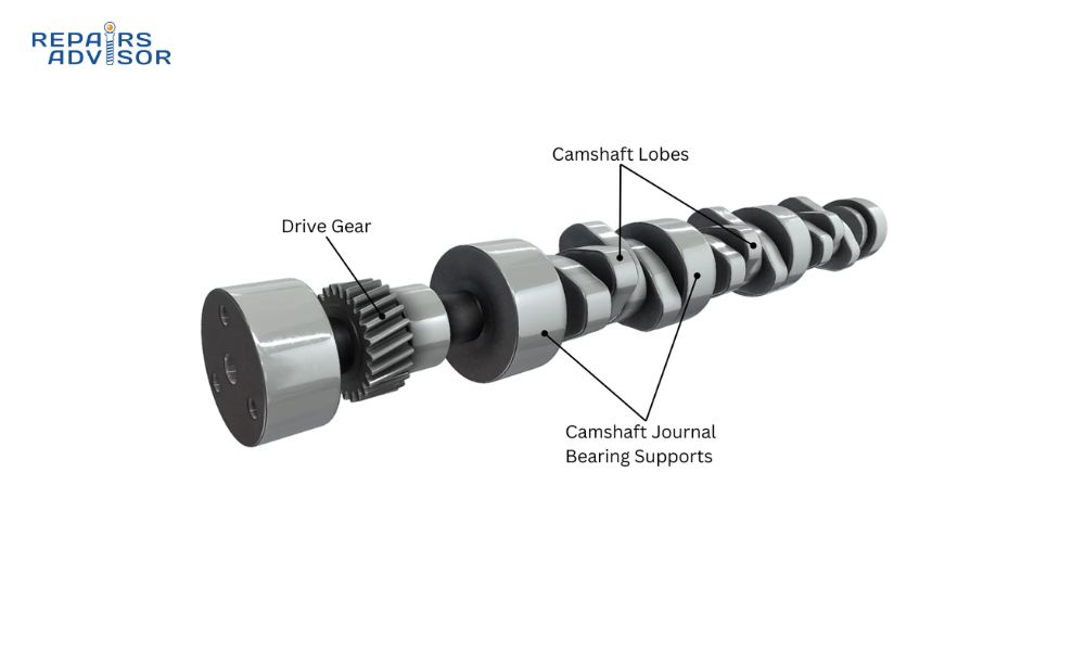
Camshaft Parts and Construction Explained
Understanding camshaft construction helps diagnose wear patterns and timing issues while providing insight into how different designs affect engine performance and maintenance requirements.
Camshaft Core and Journals: The main shaft provides structural integrity and rotates in precisely machined bearing surfaces within the engine block or cylinder head. Journal diameter and surface finish directly affect oil film thickness and bearing longevity. Professional mechanics recognize that journal wear patterns often indicate oiling issues or timing chain problems.
Cam Lobes: These precisely shaped protrusions contact lifters, pushrods, or rocker arms to actuate valves. Lobe profiles determine valve lift height, opening duration, and timing characteristics. Each lobe has three critical areas: the base circle (valve closed), ramp sections (gentle opening/closing transitions), and nose (maximum lift point).
Cam Lobe Geometry: Each lobe’s profile determines three critical measurements: maximum lift (typically 8-15mm), duration at .050″ lift (180-280 degrees), and lobe separation angle (104-114 degrees). Professional engine builders select profiles based on RPM range – narrow lobe separation angles (104-108°) improve low-end torque, while wider angles (110-114°) optimize high-RPM breathing.
The choice between hydraulic lifters and solid lifters significantly affects cam design – hydraulic lifters automatically adjust for thermal expansion and wear using oil pressure, allowing for quieter operation but limiting high-RPM performance due to lifter pump-up. Solid lifters require manual adjustment but provide more precise valve control at high RPM, making them preferred for performance applications. Intermediate enthusiasts should inspect lobes for wear patterns, pitting, or profile changes that affect valve operation.
Cam Timing Gears or Sprockets: These connect the camshaft to the engine timing system, maintaining precise synchronization with crankshaft rotation. Timing chain or belt systems require proper tensioning and alignment to prevent timing drift. Professional diagnosis includes checking gear wear, chain stretch, and tensioner operation.
Camshaft Position Sensor Triggers: Modern engines use trigger wheels or reluctor rings to provide camshaft position sensor signals for cylinder identification and cam phasing control. These components enable precise ignition timing and sequential fuel injection, while also providing feedback for variable valve timing systems to adjust cam timing advance/retard based on engine load and RPM. Sensor target accuracy directly affects timing precision – worn or damaged trigger wheels can cause timing variations that affect performance and emissions compliance.
For Overhead Cam Designs: The camshaft operates directly on valve stems through shim-over-bucket or rocker arm arrangements. This design reduces valvetrain mass and improves high-RPM performance but requires precise valve seats and guides alignment.
For Pushrod Designs: The camshaft operates through lifters and pushrods to actuate rocker arms. This design allows for lower engine height but increases valvetrain mass and limits high-RPM performance compared to overhead cam systems.
How Camshafts Work: Step-by-Step Operation
The camshaft operation cycle demonstrates the precise mechanical timing that enables four-stroke engine operation, from intake valve opening through exhaust valve closing.
Step 1 – Intake Valve Opening: As the piston moves down on the intake stroke, the camshaft’s intake lobe contacts the lifter or rocker arm, progressively opening the intake valve. The lobe’s ramp profile ensures smooth valve acceleration, minimizing valve bounce and noise. Opening timing typically occurs several degrees before top dead center to maximize cylinder filling at higher RPMs.
Step 2 – Intake Valve Duration: The valve remains open while the lobe’s nose maintains maximum lift, allowing maximum airflow into the cylinder. Cam duration, measured at 0.050″ lifter rise, typically ranges from 200-280 crankshaft degrees for street engines, with racing profiles extending to 300+ degrees. Longer duration profiles keep valves open longer, improving high-RPM breathing but potentially reducing low-RPM torque due to reduced cylinder pressure during compression. The lift coefficient (ratio of maximum valve lift to base circle diameter) directly affects airflow capacity – higher coefficients increase flow but require stronger valve springs and more precise timing control.
Step 3 – Intake Valve Closing: The lobe’s closing ramp gradually reduces valve lift, allowing valve springs to close the valve smoothly. Closing timing affects compression ratio and power delivery characteristics. Late closing can improve high-RPM power but may reduce low-end torque.
Step 4 – Compression and Power Strokes: Both valves remain closed while the piston compresses the air-fuel mixture and combustion occurs. The camshaft continues rotating but the base circle maintains valve closure. This period allows maximum compression and power transfer to the crankshaft.
Step 5 – Exhaust Valve Opening: Near the end of the power stroke, the exhaust cam lobe begins opening the exhaust valve to initiate exhaust gas evacuation. Early opening timing sacrifices some power stroke duration but improves exhaust flow and reduces pumping losses.
Step 6 – Valve Overlap Period: Both intake and exhaust valves may be partially open simultaneously, creating valve overlap timing that typically lasts 15-50 crankshaft degrees. This overlap duration affects idle quality, emissions, and power characteristics across the RPM range. Tight valve overlap timing (15-25 degrees) maintains good idle quality and low-RPM torque, while generous overlap (35-50 degrees) improves high-RPM scavenging by using exhaust pulse energy to help draw in fresh intake charge. Modern cam phasing systems can adjust this overlap dynamically – advancing cam timing increases overlap for better high-RPM performance, while retarding cam timing reduces overlap for smoother idle operation.
For Intermediate Enthusiasts: Understanding valve timing events helps diagnose performance issues. Cam timing advance/retard adjustments can significantly affect engine characteristics – advancing cam timing (rotating the camshaft ahead of its normal position) increases valve overlap and typically improves high-RPM power but may cause rough idle. Retarding cam timing reduces overlap, improving idle quality and low-RPM torque but potentially reducing high-RPM performance. Retarded timing beyond specification reduces power and may cause engine knock, while excessive advance can cause valve-to-piston interference or emissions problems. Modern engines often use cam phasing systems to automatically optimize timing based on operating conditions.
For Professionals: Modern engines often incorporate variable valve timing and variable valve lift systems that modify these basic timing events based on engine operating conditions, optimizing performance across the entire RPM range.
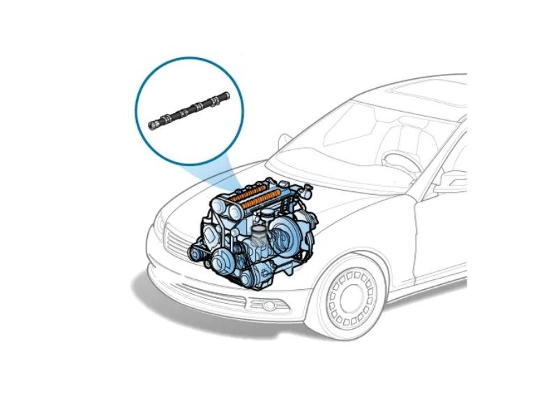
Camshaft Location and Access Guide
Proper camshaft access requires understanding engine configuration and following manufacturer-specific procedures to avoid timing system damage or valve-to-piston interference.
Overhead Cam (OHC) Engines – Single and Double Cam: In single overhead cam (SOHC) engines, one camshaft operates both intake and exhaust valves through rocker arms or directly through shim-over-bucket arrangements. Double overhead cam (DOHC) engines use separate intake and exhaust camshafts for more precise valve control and improved high-RPM performance.
Access Requirements: Overhead cam access typically requires removing the valve cover, timing belt or chain cover, and potentially intake manifold components. Professional mechanics use timing locks and alignment tools to maintain camshaft timing during service procedures.
Pushrod Engine Configuration: The camshaft is located in the engine block, typically above the crankshaft centerline. Cam lobes operate through lifters (tappets) and pushrods to actuate rocker arms at the cylinder head level.
Access Procedures: Pushrod camshaft access requires lifter removal and may necessitate engine removal or significant component disassembly. Professional service includes checking lifter bore wear, pushrod straightness, and rocker arm geometry.
Professional Service Considerations: Camshaft replacement requires precise timing alignment using manufacturer-specified timing marks and procedures. Incorrect timing can result in valve-to-piston contact and severe engine damage. Professional tools include degree wheels, dial indicators, and timing lock sets.
For Intermediate DIY: Visual camshaft inspection can reveal obvious wear or damage, but replacement typically requires professional service due to timing complexity and specialized tools. Focus on recognizing symptoms like rough idle, loss of power, or unusual valve train noise that indicate camshaft problems.
For Beginners: Camshaft location varies significantly between engine designs. Understanding your engine’s configuration helps communicate effectively with service professionals and understand repair scope and costs.
Important Safety Reminder: Never rotate the engine by hand after removing timing belts or chains without proper timing locks in place. Free-spinning camshafts can cause valve-to-piston contact and extensive engine damage.
Brand-Specific Information: Different manufacturers have unique timing procedures and special tools. For detailed procedures specific to your vehicle, consult manufacturer service manuals available through Ford manuals, Honda manuals, Toyota manuals, or other brand-specific resources.
Additional Resources: For comprehensive understanding of related systems, explore our guides on crankshaft operation, engine management systems, and timing system components.
For technical support with manual downloads or file format questions, visit our Help Center or contact our support team at [email protected].
Information provided for reference only. Always consult manufacturer specifications and qualified professionals for complex timing system work. Improper camshaft timing can result in severe engine damage.