Your vehicle’s brake system contains a critical safety component that most drivers never think about—the brake proportioning valve. This unassuming device plays a vital role in preventing dangerous rear wheel lockup during emergency braking, maintaining vehicle stability when you need it most. Understanding how this hydraulic pressure regulator works helps you recognize symptoms of failure and make informed decisions about brake system maintenance.
When you slam on the brakes in an emergency, physics works against you. Weight transfers dramatically toward the front wheels, reducing rear tire traction by 30-40%. Without proper pressure management, your rear brakes would lock up before the fronts, causing your vehicle to spin out of control—exactly what you don’t want in a panic stop. The brake proportioning valve solves this problem by automatically reducing hydraulic pressure to the rear brakes during hard braking, ensuring your vehicle stops straight and maintains directional stability.
This component is particularly critical on vehicles with front disc and rear drum brake combinations, where drum brakes are more sensitive to hydraulic pressure and prone to premature lockup. Modern engineering has refined proportioning valve design to the point where most drivers never experience rear wheel lockup, but this safety comes with a trade-off—when these valves fail, the symptoms can be subtle yet dangerous.
Whether you’re experiencing unusual braking behavior, planning brake system modifications, or simply want to understand how your vehicle’s safety systems work, this comprehensive guide explains brake proportioning valve operation, types, adjustment procedures, and failure diagnosis. We’ll cover everything from basic hydraulic principles to modern electronic proportioning systems that have replaced mechanical valves in newer vehicles.
For more context on how proportioning valves fit into your complete brake system, see our guides on master cylinder and brake booster operation and disc brake system fundamentals.
Critical Safety Note: Brake system work requires specialized knowledge, proper tools, and technical expertise. Proportioning valve adjustment directly affects vehicle safety and stopping performance. This article provides educational information to help you understand how these systems work, but any brake system service should be performed only by qualified technicians with appropriate training and equipment. If you experience any brake problems—unusual noises, pedal changes, pulling, or warning lights—have your vehicle inspected by a professional immediately.
Understanding Brake Proportioning Valves: Components and Design
A brake proportioning valve functions as a hydraulic pressure regulator specifically designed to reduce rear brake force during heavy braking situations. This component manages what engineers call “brake bias” or “brake balance”—the distribution of braking force between front and rear wheels. By limiting pressure sent to the rear brakes once system pressure exceeds a predetermined threshold, the proportioning valve prevents rear wheel lockup while maintaining optimal overall stopping power.
The fundamental problem these valves solve relates to weight transfer physics. During braking, deceleration forces push weight forward onto the front axle. In a typical panic stop, 60-70% of the vehicle’s weight concentrates on the front tires, leaving rear tires with significantly reduced traction. Without proportioning, equal hydraulic pressure to all four wheels would cause the lightly loaded rear wheels to lock up first, creating an unstable condition where the rear of the vehicle attempts to overtake the front—a dangerous scenario on any road surface.
This issue becomes particularly acute on vehicles equipped with front disc and rear drum brakes, a common configuration on many passenger vehicles through the early 2000s. Drum brakes incorporate a self-energizing mechanical advantage that makes them more aggressive than disc brakes at equivalent hydraulic pressures. The proportioning valve compensates for this difference, ensuring that the more powerful rear drums don’t overpower the limited traction available during hard stops.
For intermediate DIY mechanics, understanding brake proportioning valve operation helps diagnose braking problems and evaluate whether symptoms point to valve failure or other brake system issues. Professional technicians use this knowledge to properly adjust aftermarket proportioning valves when brake system modifications alter the factory-intended brake bias. Even beginners benefit from this understanding—recognizing that a properly functioning proportioning valve is essential for safe vehicle operation helps you make informed decisions about when professional service is necessary.
The relationship between proportioning valves and other brake components creates an integrated system where each part depends on the others. The master cylinder generates hydraulic pressure, the proportioning valve modulates that pressure to the rear circuit, and the brake calipers convert that controlled pressure into mechanical clamping force. Understanding this chain of pressure control reveals why proper proportioning valve function is non-negotiable for vehicle safety.
Types of Proportioning Valves: Design Variations
Brake proportioning valves come in several distinct designs, each suited to specific applications and vehicle configurations. Understanding these types helps you identify what your vehicle has and recognize when replacement or adjustment might be necessary.
Master Cylinder-Mounted Proportioning Valves integrate directly into the master cylinder body itself, with the proportioning mechanism built into the outlet ports leading to the rear brake circuit. This compact design eliminates external plumbing and reduces potential leak points. You’ll find this configuration on many modern vehicles where packaging space is limited. These integrated valves are fixed-ratio devices calibrated specifically for the vehicle’s weight distribution and brake component specifications. They cannot be adjusted and must be replaced as a unit with the master cylinder if they fail. The advantage lies in simplicity and reliability—fewer connections mean fewer failure points.
Combination Valve Systems represent the most common design found on domestic vehicles manufactured from 1968 through the 2000s. These multi-function units house three separate systems in one compact assembly: a proportioning valve for rear pressure reduction, a metering valve that delays front brake application slightly to allow rear brakes to engage first, and a pressure differential switch that triggers the brake warning light if hydraulic failure occurs in either circuit. The combination valve typically mounts directly below the master cylinder on the firewall or inner fender well, with brake lines connecting at multiple ports clearly marked for front and rear circuits.
General Motors, Ford, and Chrysler vehicles extensively used combination valves, making them one of the most frequently encountered proportioning valve types. The pressure differential switch serves a dual safety function—it not only warns of hydraulic failures but can also trip during brake bleeding procedures if pressure imbalance occurs between circuits. This tripping behavior sometimes confuses DIY mechanics who find no fluid flow during bleeding until the valve is reset (covered in diagnosis section below).
Inline Adjustable Proportioning Valves are aftermarket performance components installed in the rear brake hydraulic line between the master cylinder and rear brake assemblies. These valves feature external adjustment mechanisms—either a rotating knob for fine-tuning or a lever with distinct click positions for rapid adjustment. Aftermarket proportioning valves become essential when brake system modifications alter the factory brake bias, such as when converting from rear drums to rear discs, installing larger front brake calipers, or making significant suspension changes that affect weight distribution.
Knob-style adjustable valves offer continuous adjustment across their pressure range, typically providing 30-60% pressure reduction at maximum adjustment. Each rotation of the knob changes spring preload on the proportioning piston, moving the activation point (split point or “knee point”) up or down the pressure curve. This allows precise tuning for specific vehicle setups and driving conditions. Lever-style valves provide 5-7 distinct positions for quicker adjustment, making them popular for track use where drivers want to optimize brake bias for different circuit conditions or tire wear states.
Load-Sensing Proportioning Valves represent an older technology found primarily on pickup trucks and some 1970s-1990s passenger vehicles with significant rear load variation. These mechanical systems use a lever connected between the vehicle chassis and rear axle housing. As the vehicle loads up with cargo or passengers, the rear suspension compresses, changing the angle of this lever and mechanically adjusting the proportioning valve’s split point to allow more rear brake pressure when additional rear weight increases available traction. Conversely, when the truck bed is empty and the rear suspension extends, the valve reduces rear brake pressure more aggressively to prevent lockup of the lightly loaded rear wheels.
While ingenious in design, load-sensing systems suffered from wear in the mechanical linkages, corrosion of pivot points, and calibration drift over time. Modern vehicles have largely abandoned this approach in favor of electronic proportioning systems that accomplish the same goal through wheel speed sensors and ABS intervention, eliminating the mechanical complexity and maintenance requirements.
Understanding these different valve types helps you identify what your vehicle uses and sets proper expectations for serviceability. Fixed valves cannot be adjusted—attempting to modify a factory proportioning valve or combination valve destroys the calibration and compromises safety. Only true adjustable aftermarket valves should ever be tuned, and only when brake system modifications make adjustment necessary. For detailed information on how hydraulic pressure flows through these systems, see our article on brake fluid properties and hydraulic force transmission.
Brake Proportioning Valve Operation: Step-by-Step Mechanics
The internal operation of a brake proportioning valve demonstrates elegant mechanical engineering that automatically responds to braking intensity without requiring electronic controls or driver input. Understanding this step-by-step process reveals why these devices are so reliable and why they’re critical to safe vehicle operation.
Normal Braking: Unrestricted Flow Phase
During light to moderate braking—the vast majority of everyday driving situations—the proportioning valve remains completely transparent to the system, passing hydraulic pressure through at a 1:1 ratio with no reduction. When you press the brake pedal gently for a routine stop, the master cylinder generates hydraulic pressure typically ranging from 50-400 PSI depending on pedal force. This pressure travels through brake lines to the proportioning valve inlet port.
Inside the valve body, a spring-loaded piston sits in its rest position, held open by spring force. The hydraulic passage through the valve remains unrestricted, allowing brake fluid to flow freely from the inlet to the outlet port. At this stage, both front and rear brake circuits receive identical pressure from their respective master cylinder outlets. The front brakes and rear brakes engage proportionally, with no pressure reduction occurring at the rear. This normal operation is appropriate because gentle braking produces minimal weight transfer—rear wheels retain sufficient traction to handle the braking force without approaching lockup conditions.
For professional technicians, understanding that the valve is “transparent” below its activation threshold is crucial for proper diagnosis. Many brake problems attributed to proportioning valves actually stem from other components, because the valve only actively modulates pressure during hard braking events that exceed the split point. If a vehicle exhibits brake problems during normal driving—soft pedal, excessive travel, pulling—the proportioning valve is unlikely to be the cause since it isn’t even actively functioning in that pressure range.
The pressure threshold where proportioning begins varies by vehicle and valve design, typically falling between 500-800 PSI for most passenger vehicles. Heavier trucks may have higher thresholds (700-900 PSI), while lighter vehicles might activate proportioning at lower pressures. This calibration point, called the “split point” or “knee point,” determines when the valve transitions from passive pass-through to active pressure reduction.
Heavy Braking: Proportioning Activation Phase
When you apply heavy pedal force during an emergency stop or aggressive deceleration, master cylinder output pressure spikes dramatically—often reaching 1,200-1,500 PSI at the front circuit during a panic stop. This high-pressure surge triggers the proportioning valve’s active phase, where it begins reducing rear brake pressure to prevent wheel lockup.
As system pressure climbs above the split point threshold, hydraulic force acting on the larger inlet side of the proportioning piston overcomes the spring preload holding it open. The piston begins moving against spring resistance, progressively closing off the direct hydraulic passage and forcing fluid through a restricted pathway. This restriction creates a pressure differential—input pressure continues rising proportionally with pedal force, but output pressure to the rear brakes increases at a significantly reduced rate.
The mechanical advantage of differential piston areas creates this pressure reduction. A typical proportioning valve might have a 0.75-inch diameter piston on the inlet side (0.44 square inches of area) and a 0.50-inch diameter on the outlet side (0.20 square inches). This roughly 2:1 area ratio means that above the split point, rear brake pressure rises at approximately half the rate of front brake pressure. Combined with spring resistance, this creates the characteristic proportioning curve where rear pressure plateaus well below front pressure during hard stops.
The beauty of this mechanical system lies in its proportional response. Unlike an on-off valve that would create harsh engagement, the proportioning valve progressively reduces rear pressure in proportion to braking intensity. The harder you brake, the more weight transfers forward, and the more aggressively the valve limits rear pressure. This automatic scaling perfectly matches the physics of weight transfer, maintaining optimal brake balance across a wide range of braking intensities.
Modern ABS systems work in conjunction with proportioning valves during panic stops. The proportioning valve establishes the baseline pressure distribution, while ABS modulates individual wheel pressures at up to 15 times per second if wheel speed sensors detect impending lockup. This layered approach provides both mechanical pressure limitation (proportioning) and electronic fine-tuning (ABS), creating robust anti-lockup protection even in challenging conditions like wet or icy roads.
For those interested in the complete hydraulic control chain, understanding how the master cylinder and brake booster generate and amplify pedal force provides context for the pressure levels that trigger proportioning valve operation.
Brake Release and System Reset
When you release the brake pedal, master cylinder pressure drops instantly to zero as the pistons retract and open the hydraulic circuits to the reservoir. The proportioning valve responds immediately to this pressure drop. Spring force pushes the proportioning piston back to its fully open rest position, restoring the unrestricted hydraulic passage through the valve. The system resets automatically—no driver intervention or manual reset is required for normal operation.
Some brake systems incorporate residual pressure check valves (typically 2-10 PSI retention) in the proportioning valve or brake lines. These small spring-loaded check valves prevent complete pressure bleed-back when the pedal releases, maintaining slight residual pressure to keep brake pads close to rotors or brake shoes near drums. This residual pressure improves pedal response on the next brake application by eliminating the “dead travel” that would otherwise occur as pressure rebuilds to overcome return springs. Residual valves are more common on drum brake circuits where return springs exert significant force.
The release and reset phase happens in milliseconds, making the system ready for the next brake application without delay. This automatic operation is one reason proportioning valves are so reliable—there are no electronic controllers to fail, no complex calibration procedures, and no maintenance requirements beyond keeping the hydraulic system properly bled and sealed against leaks. The mechanical simplicity translates to decades of reliable service in most applications.
However, this simplicity can be interrupted by one service-related issue: valve tripping during brake bleeding. Combination valves with pressure differential switches can detect the pressure imbalance created during manual brake bleeding (when one circuit is open to atmosphere through a bleeder screw) and trip the warning switch. When this happens, the proportioning valve may lock in an off-center position, preventing proper fluid flow. Reset procedures vary by valve design but typically involve applying and releasing the brake pedal while monitoring for fluid flow, sometimes requiring specific tool insertion to hold the differential piston centered during bleeding. Professional technicians use proportioning valve bleeder tools—essentially dummy switches that mechanically hold the piston centered—to prevent tripping during service.
Adjusting Proportioning Valves: Professional Tuning Procedures
Factory-installed proportioning valves—whether integrated into the master cylinder, part of a combination valve, or inline fixed units—should never be adjusted. These valves are precisely calibrated for the vehicle’s specific weight distribution, brake component specifications, and intended use. The factory brake bias represents extensive engineering analysis and real-world testing to achieve optimal stopping power with maximum stability across the vehicle’s operational envelope.
However, aftermarket adjustable proportioning valves serve a critical function when brake system modifications alter the factory brake bias. Understanding when adjustment is necessary and how to safely perform it helps prevent dangerous brake imbalances that could compromise vehicle control during emergency stops.
When Proportioning Valve Adjustment Becomes Necessary
Several common modifications fundamentally change brake bias and require proportioning valve adjustment to restore safe brake balance. Converting from rear drum brakes to rear disc brakes dramatically increases rear braking capacity—disc brakes produce more consistent force and lack the self-energizing effect of drums. Without adjustment, the increased rear brake effectiveness can cause premature rear lockup. Installing a rear disc conversion kit almost always necessitates adding an adjustable proportioning valve if the vehicle originally used a fixed valve calibrated for drums.
Similarly, installing a front big brake kit with larger calipers and rotors increases front braking capacity substantially. If rear brakes remain stock, the imbalanced system may cause excessive front-end dive and underutilize rear brake capacity. An adjustable proportioning valve allows increasing rear pressure to restore proper balance. Significant suspension modifications—lowering springs, heavy-duty shocks, weight reduction—can shift weight distribution enough to warrant brake bias adjustment, particularly on track-focused builds.
Pickup trucks present a unique case where load variation affects optimal brake bias. An empty truck has minimal rear weight and needs aggressive proportioning to prevent rear lockup, while a fully loaded truck requires more rear brake force to handle the additional weight. While factory load-sensing valves addressed this mechanically, modern trucks typically use electronic proportioning that automatically adapts. Installing aftermarket suspension lifts or heavy cargo systems may require manual proportioning valve installation and adjustment.
Critical Safety Warning: Proportioning valve adjustment affects vehicle safety directly. Incorrect adjustment can cause dangerous brake imbalance—either rear wheel lockup that destabilizes the vehicle or excessive front brake bias that extends stopping distances and causes premature front component wear. This adjustment should only be performed by experienced technicians or very knowledgeable enthusiasts who understand brake system dynamics and have access to safe testing environments. When in doubt, consult professional brake specialists who regularly perform this work.
Professional Adjustment Procedure and Testing Protocol
Adjustable proportioning valve tuning requires a methodical approach in controlled conditions. The standard procedure used by professional shops and experienced builders follows these steps:
Preparation Phase: Ensure the brake system is in perfect working condition before adjustment. Complete all brake work—pad replacement, rotor resurfacing, caliper service—and thoroughly bleed the system to remove all air. Verify that tires are inflated to manufacturer specifications, as tire pressure significantly affects brake performance and lockup threshold. Test with approximately half a tank of fuel to represent normal operating weight, no passengers, and minimal cargo. This standardization ensures consistent results.
Initial Setting: Position the adjustable proportioning valve to minimum rear pressure. On knob-style valves, turn the adjustment knob fully counterclockwise (typically 10-15 complete rotations) until it stops. On lever-style valves, set the lever to the position marked “minimum” or farthest from the valve body. This conservative starting point prevents rear lockup during initial testing.
Controlled Testing Environment: Find a safe testing location—a large empty parking lot with good pavement and no traffic is ideal. Have an observer positioned safely outside the vehicle where they can clearly see all four wheels during testing. The observer’s role is critical since the driver cannot see which wheels lock first during hard braking.
Testing Procedure: Accelerate to 30 MPH on dry pavement. Apply firm, progressive brake pressure—not quite hard enough to trigger ABS or lock wheels, but aggressive enough to cause significant weight transfer. The observer watches which wheels begin locking or skidding first. The goal is achieving front wheel lockup just before the rears, or ideally, all four wheels reaching lockup threshold simultaneously. This represents optimal brake balance where maximum braking force is being used at all four corners without any wheel losing traction before the others.
Adjustment Strategy: Interpret test results and adjust accordingly. If only the front wheels lock while the rears continue rolling freely, the rear brakes need more pressure—turn the knob clockwise 2 full turns (or advance the lever one position) to increase rear brake force. If the rear wheels lock before the fronts, reduce rear pressure by turning counterclockwise. Make incremental 2-turn adjustments between tests to avoid overcorrection. Each adjustment changes the split point where proportioning begins, affecting how much pressure reaches the rear brakes during hard stops.
Higher Speed Verification: Once initial 30 MPH tuning achieves near-simultaneous lockup, repeat testing at 50 MPH. Higher-speed stops create more weight transfer, so this verification ensures the adjustment remains appropriate across a realistic speed range. Minor tweaking may be necessary to optimize for higher-speed performance.
Documentation: Record the final setting by counting turns from fully counterclockwise. For example, “8 turns in from fully out” provides a reference point if the valve is ever removed for service or if adjustment needs revisiting after further modifications. Some enthusiasts mark the knob position with paint or tape for easy visual reference.
Lever-Style Valve Considerations: Lever-type adjustable proportioning valves offer 5-7 distinct click positions instead of continuous adjustment. Use the same testing procedure but adjust one position at a time. The advantage of lever valves is in-vehicle adjustment capability—drivers can change settings between track sessions to compensate for fuel burn-off, tire wear, or changing track conditions. However, this convenience comes with responsibility—never adjust while driving, and verify changes in controlled conditions before competition.
Alternative Professional Testing: Pressure Gauge Method
Experienced shops may use brake pressure gauges instead of lockup testing. This method installs pressure gauges in the front and rear brake circuits (typically at bleeder screws or via T-fittings). With the vehicle stationary, the technician applies heavy pedal force while monitoring pressure readings. Proper proportioning typically shows front pressures reaching 1,200-1,500 PSI while rear pressure plateaus at 500-800 PSI, though specific targets vary by vehicle weight and brake component specifications.
Pressure gauge testing eliminates the variables and risks of dynamic testing—no need for empty parking lots, no tire wear from lockup testing, and precise numerical verification of proportioning action. However, it requires specialized equipment and knowledge of appropriate pressure targets for specific vehicle configurations. For DIY adjusters, the dynamic lockup test remains the more accessible approach, though it demands strict attention to safety protocols and controlled testing conditions.
For vehicles equipped with modern electronic systems, understanding how electronic stability control integrates with brake pressure distribution provides context for why mechanical proportioning adjustments can conflict with electronic controls.
Diagnosing Proportioning Valve Problems: Symptoms and Testing
Proportioning valve failures manifest in ways that can be subtle during normal driving but become dangerous during emergency stops. Recognizing these symptoms helps you identify when professional brake system diagnosis is needed before a failure creates a dangerous situation.
Primary Failure Symptoms and Warning Signs
Rear Wheel Premature Lockup stands as the most definitive symptom of proportioning valve failure, though it may only appear during hard braking that triggers the valve’s active phase. During moderate to hard stops, the rear wheels skid or slide before the front wheels reach their traction limit. This condition is particularly noticeable on wet, icy, or loose surfaces where available traction is already reduced. On dry pavement with good tires, you might only experience this during truly aggressive stops.
The danger of premature rear lockup extends beyond just tire squealing. When rear wheels lose traction before fronts, the vehicle’s tail wants to swing around—a condition called “oversteer” or “rotation.” On anything other than perfectly straight braking, this can initiate a spin. The vehicle becomes directionally unstable, potentially causing the rear to overtake the front during panic stops. This is exactly what proportioning valves are designed to prevent, so experiencing this symptom indicates serious proportioning valve failure or, in modified vehicles, severe brake bias misadjustment.
A safe testing method involves finding an empty parking lot and making medium-hard stops from 30 MPH (never attempt this on public roads). Have someone observe from a safe distance outside the vehicle. If rear tires visibly lock or skid before fronts, valve failure is confirmed. However, never rely solely on self-testing—professional diagnosis using brake pressure gauges provides definitive confirmation without the risk inherent in deliberately inducing wheel lockup.
Excessive Front-End Dive during braking may indicate the proportioning valve has failed in a closed or overly restrictive position. When rear brakes contribute inadequately to stopping power, the front brakes must work disproportionately hard, causing dramatic nose-down pitch during stops. While some front-end dive is normal—weight transfer is a physical reality—excessive dive that seems out of proportion to braking intensity suggests rear brake underutilization.
This symptom proves harder to diagnose definitively than rear lockup because front-end dive can result from multiple issues: worn front suspension components, weak shock absorbers, or front brake problems. However, if combined with other symptoms like minimal rear brake pad wear compared to front, proportioning valve investigation becomes warranted.
Uneven Brake Component Wear Patterns provide diagnostic clues over time. If rear brake pads or shoes show minimal wear compared to front pads, the rear brakes aren’t contributing their proper share of braking force. Conversely, if rear brakes wear excessively fast—burning through pads while fronts remain thick—the valve may be stuck open or failed, sending too much pressure rearward. Inspect brake pads during routine service. Front pads typically wear 20-30% faster than rears in properly balanced systems, but extreme discrepancies (front pads at 30% remaining while rears are at 90%) indicate potential proportioning issues.
Brake Warning Light Illumination occurs when combination valves detect pressure differential between circuits. The pressure differential switch inside combination valves triggers the dashboard brake warning light if it senses imbalance between front and rear hydraulic circuits. This can indicate actual hydraulic failure in one circuit, but it can also trip during brake bleeding if air enters the system or if bleeding procedure creates temporary pressure imbalance. The warning light deserves immediate professional attention—it could indicate anything from a minor bleeding issue to serious brake line failure or proportioning valve internal damage.
One peculiarity of combination valves: they can trip and hold during brake bleeding, preventing fluid flow even after the bleeding procedure is completed correctly. This frustrates many DIY mechanics who find one circuit won’t bleed despite repeated attempts. The solution involves resetting the pressure differential valve (procedures vary by manufacturer) or using a proportioning valve bleeder tool that holds the differential piston centered during service.
Extended Stopping Distances represent perhaps the most dangerous symptom because they may develop gradually enough that drivers don’t notice. If the proportioning valve fails in a way that severely limits rear brake contribution, overall stopping power decreases. The front brakes reach their traction limit while rear brakes remain underutilized, leaving braking performance on the table. This reduction in stopping effectiveness may not be obvious during normal driving but becomes critical during emergency stops where every foot matters.
Unfortunately, extended stopping distances prove difficult to self-diagnose because few drivers have objective baseline measurements for their vehicle’s stopping performance. Professional brake testing equipment can measure deceleration rates and stopping distances, revealing deficiencies that wouldn’t be apparent to the driver. If you suspect stopping performance has degraded, professional evaluation is essential.
Professional Diagnostic Testing Methods
Brake Pressure Gauge Testing represents the definitive diagnostic method for proportioning valve evaluation. Professional shops install pressure gauges into the front and rear hydraulic circuits—typically via adapter fittings at the brake line connections or bleeder screw locations. With the vehicle stationary and the engine running (for power brake booster function), the technician applies progressively harder pedal force while monitoring pressure gauges.
Proper proportioning valve operation shows characteristic pressure curves. At low pedal force (under 500 PSI typically), front and rear pressures rise identically—the valve is still in passive mode. As pedal force increases past the split point, front pressure continues rising linearly toward 1,200-1,500 PSI, while rear pressure increase rate dramatically slows, plateauing in the 500-800 PSI range depending on vehicle specifications. If rear pressure continues climbing in direct proportion to front pressure throughout the entire pedal travel, the proportioning valve has failed in the open position.
Conversely, if rear pressure shows little or no increase while front pressure rises normally, the valve has failed in a closed or overly restrictive condition. Partial failures can occur where the valve activates too early (low split point) or too late (high split point), creating suboptimal brake balance even though some proportioning action still occurs.
Pressure gauge testing eliminates ambiguity and provides numerical verification of proportioning function. However, it requires expensive specialized equipment and knowledge of appropriate pressure specifications for the specific vehicle—information not always readily available even to professional technicians for older or modified vehicles.
Visual Inspection Protocol reveals some proportioning valve problems without specialized tools. With the vehicle safely raised on jack stands, inspect the proportioning valve body and all connected brake lines for signs of leakage. Brake fluid weeping from the valve body, around adjustment knobs, or at threaded connections indicates seal failure that will cause brake performance degradation and eventual fluid loss. Combination valves are particularly prone to corrosion at the valve body itself, especially in rust-belt climates where road salt exposure accelerates corrosion.
Check that brake line connections are tight using a proper flare-nut wrench (not regular open-end wrenches, which can round off brass fittings). Verify the electrical connector for the brake warning switch shows clean terminals with no corrosion or damage. On vehicles with load-sensing proportioning valves, inspect the mechanical linkage between chassis and axle for wear, damage, or disconnection—a common failure mode that leaves the valve stuck in one position.
For combination valves, look for any physical damage to the valve body, brackets, or mounting hardware. These components mount in exposed locations under the master cylinder where they can be damaged during other service work. A bent mounting bracket or cracked valve body can cause internal damage or misalignment that prevents proper operation.
When Professional Diagnosis Becomes Mandatory
Any symptom that affects brake performance requires immediate professional evaluation. Braking systems are critical safety components where component failures can have life-threatening consequences. Don’t attempt to self-diagnose or ignore symptoms hoping they’ll resolve themselves. Modern brake system diagnosis requires specialized knowledge, tools, and experience that professional technicians possess.
Schedule inspection immediately if you experience: rear wheel lockup during braking, brake warning light illumination, unusual brake pedal feel or travel, pulling to one side during stops, any brake fluid leaks, or concerns about stopping effectiveness. Professional shops have diagnostic equipment, technical service bulletins, manufacturer specifications, and the experience necessary to accurately identify root causes and recommend appropriate repairs.
For comprehensive information on related brake hydraulics components, see our complete guide to brake fluid properties and system maintenance. Understanding how hydraulic systems function throughout your brake system provides valuable context for proportioning valve operation.
Electronic Brake Proportioning: ABS Integration and Modern Technology
While mechanical proportioning valves dominated brake system design from the 1960s through 1990s, modern vehicles increasingly eliminate these mechanical components in favor of electronic brake proportioning integrated within ABS systems. This technology shift represents more than simple component replacement—it fundamentally changes how brake balance is achieved and managed.
Dynamic Rear Proportioning and Electronic Brake-Force Distribution
Electronic proportioning systems—called Dynamic Rear Proportioning (DRP) by General Motors, Electronic Brake-force Distribution (EBD) by Toyota and most Asian manufacturers, or simply Electronic Brake Proportioning (EBP) by Ford—leverage existing ABS hardware to perform proportioning functions without any dedicated proportioning valve. The system uses the same wheel speed sensors, hydraulic control unit (HCU), and electronic control unit (ECU) that enable anti-lock braking to also manage brake balance dynamically.
The operational principle differs fundamentally from mechanical proportioning. Rather than reacting to hydraulic pressure levels in the brake lines, electronic systems monitor actual wheel speeds during braking. The ABS controller continuously calculates slip ratios for all four wheels—the relationship between wheel rotational speed and vehicle speed. When rear wheels begin approaching lockup threshold (indicated by rear wheel slip exceeding front wheel slip by a calibrated amount), the controller activates ABS solenoid valves to reduce pressure specifically to the rear wheels.
This electronic intervention occurs before actual lockup—the system reads imminent traction loss from wheel speed data and prevents it proactively. The hydraulic modulation happens in milliseconds, with pressure adjustments occurring 10-15 times per second if necessary. Unlike mechanical proportioning valves that establish a fixed pressure relationship above the split point, electronic systems adapt to real-time traction conditions at each individual wheel.
The advantages over mechanical systems prove substantial. Electronic proportioning automatically compensates for varying vehicle loads—passengers, cargo, fuel level—without any mechanical load-sensing linkage. The system adapts to mixed-traction surfaces where one rear wheel encounters ice or water while the other has dry pavement, something mechanical valves cannot address since they treat both rear wheels identically. Tire pressure variations, tire wear differences, and even brake pad condition variations can be compensated electronically in ways mechanical valves cannot match.
Integration with other vehicle systems provides additional benefits. Electronic proportioning works seamlessly with traction control, electronic stability control, and regenerative braking in hybrid or electric vehicles. The same hardware serves multiple safety functions, reducing component count, weight, and potential failure points. From a manufacturer’s perspective, eliminating mechanical proportioning valves reduces costs while improving functionality—a rare win-win in automotive engineering.
Implications for Modified Vehicles and Limitations
Electronic proportioning systems present challenges for enthusiasts performing brake system modifications. Unlike mechanical valves that can be replaced with adjustable aftermarket units, electronic systems are embedded in the ABS controller’s programming and cannot be easily modified or adjusted. The control algorithms are optimized for specific vehicle configurations—brake component sizes, weight distributions, suspension geometries—and don’t adapt to significant modifications.
Installing larger brake calipers, converting from drums to discs, or making substantial suspension modifications can push the vehicle outside the electronic proportioning system’s calibration envelope. The system may still function, but brake balance might be suboptimal—either overly conservative (limiting rear brake contribution more than necessary) or insufficiently protective (allowing rear wheels closer to lockup than ideal). Unlike adjustable mechanical valves that can be tuned for modified setups, electronic proportioning offers no user adjustment.
Several approaches address this limitation in modified vehicles. The most common solution involves selecting brake component upgrades that maintain similar proportions to stock—if upgrading to larger front calipers, also upgrade rear brakes proportionally so the relative balance remains close to stock. This allows electronic proportioning to continue functioning within its design parameters. Many brake kit manufacturers offer “balanced” packages specifically designed to maintain appropriate brake bias on vehicles with electronic proportioning.
For extreme modifications where proportioning must be manually controlled, some builders add a mechanical adjustable proportioning valve in the rear brake circuit, effectively bypassing the electronic system for the rear brakes. This approach requires careful consideration—the ABS system will still attempt electronic intervention based on wheel speed data, and combining mechanical and electronic proportioning can create unexpected interactions. Professional brake specialists with experience in modified vehicle setups should be consulted before attempting this solution.
A third approach involves custom ECU tuning to modify the electronic proportioning algorithms. This option exists only for vehicles where aftermarket tuning solutions are available and requires specialized software, equipment, and knowledge. It remains the most comprehensive solution but also the most complex and expensive.
For most drivers, electronic proportioning represents a significant safety advancement that requires no maintenance, provides superior performance in varying conditions, and integrates elegantly with modern safety systems. The limitations primarily affect the small percentage of enthusiasts performing significant brake system modifications—for stock or mildly modified vehicles, electronic proportioning delivers optimal brake balance without the servicing needs of mechanical valves. For additional context on advanced electronic brake systems, see our guide to brake-by-wire technology and its integration with proportioning functions.
Finding Your Proportioning Valve: Location and Identification
Locating the proportioning valve in your specific vehicle depends significantly on the vehicle’s age, manufacturer, and brake system design. Understanding where to look and how to identify these components helps during inspection, diagnosis, or brake system service.
Location Patterns by Vehicle Age and Type
Older Vehicles (1960s-1990s) typically feature externally accessible proportioning valves that can be visually identified with some effort. On American domestic vehicles from this era, look for combination valves mounted directly under the master cylinder on the firewall or inner fender well. These cast iron or aluminum blocks measure approximately 3-4 inches long, with three to five brake line connections and a wire connector for the brake warning light switch. The combination valve serves as a central junction point where brake lines from the master cylinder split to front and rear circuits.
General Motors vehicles often mounted proportioning valves or combination valves on the driver-side frame rail near the master cylinder, secured with a single bolt or bracket. This location keeps the valve accessible for service while protecting it somewhat from road debris and weather. Ford and Chrysler typically integrated proportioning function into combination valves mounted beneath the master cylinder.
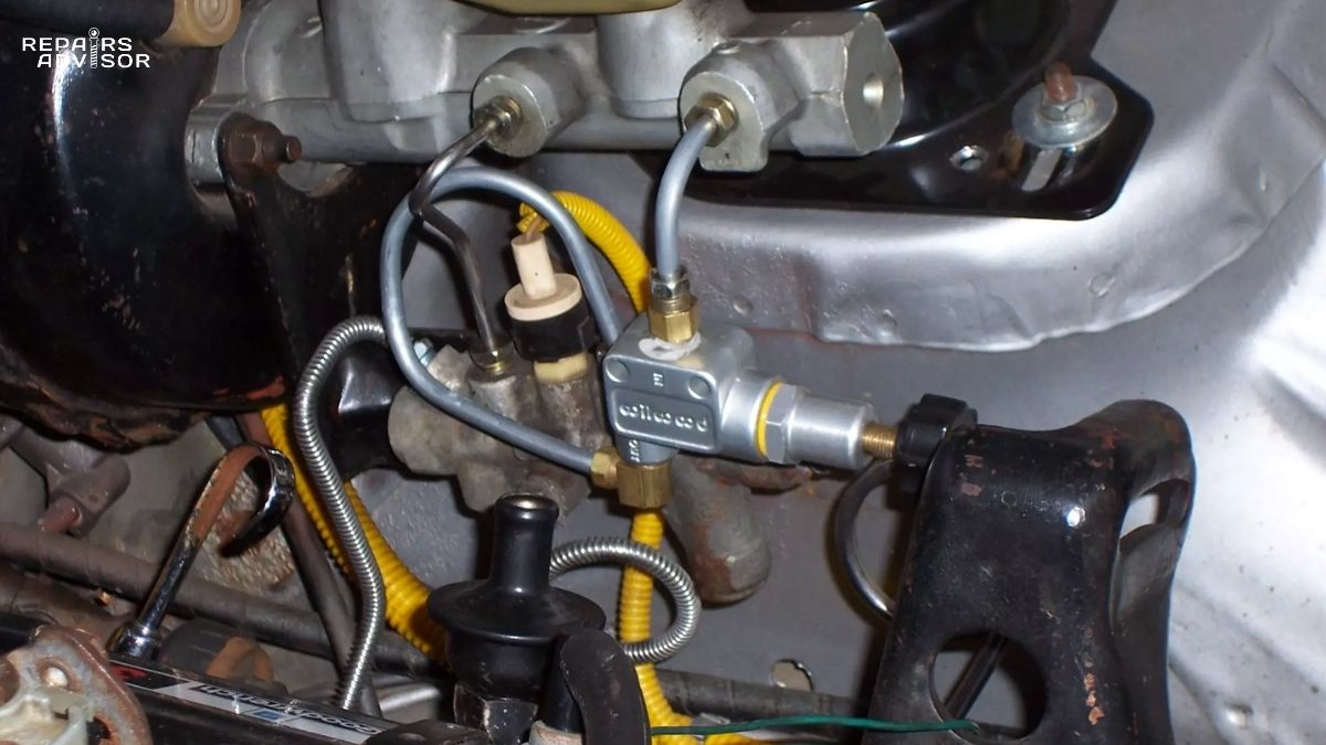
Standalone inline proportioning valves—less common on factory installations but prevalent on earlier performance or modified vehicles—appear as small cylindrical components (roughly thumb-sized) plumbed into the rear brake line. These typically mount to the frame or firewall using a simple bracket, with clear “IN” and “OUT” port markings showing hydraulic flow direction.
Modern Vehicles (2000s-Present) increasingly integrate proportioning functions internally where they’re not visible during routine inspection. Many contemporary vehicles incorporate proportioning mechanisms directly into the master cylinder body, with no external valve to identify or service. The proportioning components are built into the master cylinder’s rear circuit outlet during manufacturing, making them completely integrated and non-serviceable separately.
Alternatively, newer vehicles have eliminated mechanical proportioning entirely, relying instead on electronic brake proportioning through the ABS system. In these configurations, there is literally no proportioning valve to locate—the ABS hydraulic control unit (typically mounted near the master cylinder or on the frame rail) performs all proportioning functions electronically using solenoid valves and wheel speed sensor data.
To determine whether your vehicle uses mechanical or electronic proportioning, consult the factory service manual or brake system diagrams. As a general rule, vehicles equipped with ABS manufactured after 2005 likely use electronic proportioning, though exceptions exist. Vehicles without ABS definitely require mechanical proportioning valves since electronic proportioning depends on ABS hardware.
Visual Identification and Component Recognition
Combination Valve Identification Features:
- Cast metal body (aluminum or iron) approximately 3-4 inches long
- Multiple brake line ports (typically 4-6) with flare fittings
- Single electrical connector on top for brake warning light switch
- May have “FRONT” and “REAR” castings indicating circuit connections
- Sometimes has a small rubber cap covering bleeder/reset button on top
Adjustable Inline Valve Identification:
- Compact cylindrical body, typically 1-2 inches in diameter, 2-4 inches long
- Two brake line connections: inlet and outlet (usually marked “IN” and “OUT” or “R” for rear)
- Adjustment knob on one end (knob-style) or side-mounted lever (lever-style)
- Often aluminum with black, chrome, or natural finish
- May have pressure rating or manufacturer markings cast into body
Load-Sensing Valve Identification:
- Mounted on frame rail near rear axle (not near master cylinder)
- Mechanical linkage arm connecting valve body to rear axle housing
- Spring-loaded lever mechanism visible externally
- Larger valve body to accommodate mechanical proportioning mechanism
- Two hydraulic connections for brake fluid flow
Access Requirements and Safety Considerations
For basic visual inspection of proportioning valves, the vehicle must be safely raised and supported on jack stands—never rely solely on floor jacks for under-vehicle access. Most proportioning valve locations are accessible from underneath or through the wheel well with the tire removed. Ensure proper jack stand placement at manufacturer-specified lifting points before working beneath any vehicle.
Combination valves mounted under the master cylinder may be visible from the engine compartment, though brake line congestion can make detailed inspection difficult without removing components for access. Frame rail-mounted valves typically require under-vehicle access with the vehicle raised to working height.
Critical Safety Limitations for DIY Inspection: Proportioning valve location and visual identification falls within the capability of intermediate DIY mechanics, but service work on these components requires professional expertise. Any task involving opening hydraulic connections, removing valves, or affecting brake system integrity must be performed by qualified technicians with proper equipment. Brake fluid handling requires appropriate personal protective equipment—brake fluid damages paint and is harmful if ingested or absorbed through skin.
Never attempt to disassemble or internally service proportioning valves. These components are not designed for rebuild—they must be replaced as complete assemblies if internal failure occurs. Attempting to disassemble sealed proportioning valves or combination valves will contaminate internal components and destroy calibration, creating serious safety hazards.
For comprehensive overview of brake system components and their locations, visit our brake system category overview which covers the complete hydraulic control system and safety components.
Understanding Brake Proportioning for Safer Driving: Key Takeaways
Brake proportioning valves represent critical safety components that most drivers never think about—which is exactly how it should be when they’re functioning properly. These hydraulic pressure regulators work silently in the background, preventing dangerous rear wheel lockup during emergency stops by automatically reducing rear brake pressure in proportion to braking intensity. The mechanical elegance of these devices, whether simple inline valves or complex combination valve assemblies, exemplifies automotive safety engineering at its finest.
The fundamental physics driving proportioning valve necessity—weight transfer during braking—applies to all vehicles regardless of technological sophistication. Even modern electronic proportioning systems serve the same essential function: ensuring rear wheels don’t lose traction before front wheels during hard braking. Whether accomplished through mechanical spring-loaded pistons or electronic wheel speed monitoring, the goal remains constant: maximum stopping power with maintained directional stability.
For everyday drivers, understanding proportioning valve operation provides valuable context for brake system maintenance and helps recognize potential problems before they become dangerous. Symptoms like premature rear wheel lockup, excessive front-end dive, unusual brake pedal behavior, or illuminated brake warning lights all warrant immediate professional attention. The brake system represents your vehicle’s most critical safety system—never ignore warning signs or delay professional diagnosis when brake performance concerns arise.
Enthusiasts planning brake system modifications must carefully consider proportioning valve implications. Any change that affects brake balance—disc conversions, big brake kits, suspension modifications—requires proportioning valve evaluation and potential adjustment. Stock proportioning valves calibrated for factory configurations cannot compensate for modified setups. Consulting experienced brake specialists before purchasing components prevents expensive mistakes and ensures safe, balanced brake performance after modifications are complete.
When Professional Service Becomes Essential
Several scenarios demand immediate professional brake system inspection:
Emergency Symptoms Requiring Same-Day Service:
- Brake warning light illumination
- Brake pedal goes to floor or feels excessively soft
- Any brake fluid leaks visible under the vehicle
- Complete loss of braking on any wheel
- Vehicle pulls severely to one side during braking
- Grinding, scraping, or metal-on-metal sounds during braking
Symptoms Warranting Prompt Service (Within Days):
- Rear wheels locking during moderate to hard braking
- Excessive front-end dive when stopping
- Brake pedal requires more pressure than normal for same stopping power
- Longer stopping distances than previously experienced
- Unusual brake pedal pulsation (not ABS activation)
- Brake pad wear severely imbalanced front to rear
Modification-Related Service Needs:
- After installing any aftermarket brake components (calipers, rotors, pads)
- Following brake system bleeding or hydraulic service
- After rear drum-to-disc conversions
- Following suspension modifications that change ride height or weight distribution
- When track use or performance driving reveals brake balance issues
Professional technicians possess the specialized knowledge, diagnostic equipment, and experience necessary to accurately diagnose brake problems and perform repairs safely. Brake pressure gauges, hydraulic bleeding equipment, factory service specifications, and technical training enable professionals to service brake systems in ways that simply aren’t possible in home garages. The relatively modest cost of professional brake service represents exceptional value when compared to the safety criticality of proper brake function.
Building Your Brake System Knowledge
Understanding brake proportioning valves represents just one piece of comprehensive brake system knowledge. These components work as part of an integrated hydraulic system where every component depends on the others for proper function. Expanding your understanding to encompass the complete system—from master cylinder pressure generation through brake fluid characteristics to caliper operation at the wheels—provides valuable context for maintenance decisions and helps you communicate effectively with service professionals.
Modern brake systems integrate mechanical hydraulics with electronic controls, creating sophisticated safety systems that work seamlessly to keep you safe. Whether your vehicle uses traditional mechanical proportioning or advanced electronic brake proportioning through ABS, the underlying principles remain the same: optimize brake balance for maximum stopping power while preventing dangerous wheel lockup. This safety engineering, refined over decades of development, represents one of automotive technology’s great success stories—millions of emergency stops performed safely every day by drivers who never think about the complex systems making it possible.
When maintenance or modification time comes, informed decisions based on solid understanding of brake system operation serve you well. You’ll know which symptoms deserve immediate attention, which service recommendations make sense, and when professional expertise becomes non-negotiable. That knowledge—combined with respect for brake system complexity and safety criticality—keeps you and others safe on the road.
Final Reminder: This article provides educational information to help you understand brake proportioning valve operation and recognize symptoms requiring professional attention. Brake system service and repair should only be performed by qualified technicians with appropriate training, tools, and equipment. Never attempt brake system repairs beyond basic pad replacement if you lack the expertise, tools, and knowledge necessary to perform the work safely. When in doubt, consult professionals—your safety and the safety of others depends on properly functioning brakes.
For additional brake system information and comprehensive guides to related components, explore our complete brake system technical library covering all aspects of modern and classic brake technology.