When you turn your ignition key, press your horn button, or flip on your headlights, a small electrical switch springs into action behind the scenes. This unassuming component—the automotive relay—completes powerful circuits that would otherwise destroy your dashboard controls within hours of use. Without relays protecting your vehicle’s electrical architecture, a simple headlight switch would melt from the heat of 15-amp current flow, and your ignition switch would weld itself shut from starter motor surge currents exceeding 150 amps.
Automotive relays allow low-power control circuits to safely manage high-current devices like starter motors, fuel pumps, and cooling fans. They protect sensitive electronics while enabling reliable operation of power-hungry components throughout your vehicle. Think of a relay as a remote-controlled switch: you pull a small rope (low current through the control circuit) to close a massive power switch (high current to the device) without ever touching the dangerous high-voltage contacts yourself.
Modern vehicles contain anywhere from 10 to 50+ relays controlling everything from basic lighting to complex computer-managed systems. Understanding how these electromagnetic switches function empowers you to diagnose electrical problems, replace failed components, and appreciate the engineering sophistication hiding in plain sight under your hood. Most relay testing and replacement tasks fall well within intermediate DIY capabilities, requiring only a basic multimeter and careful attention to safety procedures.
However, some electrical issues extend beyond simple relay failure. If relay replacement doesn’t resolve your problem, or if multiple relays fail simultaneously, professional electrical diagnosis with specialized equipment may be necessary—particularly in vehicles with integrated control modules or computer-managed electrical systems. For detailed information on other electrical components, see How Automotive Fuses Work for circuit protection fundamentals and How Car Batteries Work to understand the power source that feeds relay circuits.
What Is an Automotive Relay?
An automotive relay is an electromechanical switch that uses a small control current to activate an electromagnetic coil, which then mechanically closes contacts to allow large amounts of electrical current to flow to high-power devices. This simple but ingenious design solves a fundamental problem in vehicle electrical systems: sensitive control switches and computer modules cannot safely handle the 20-40+ amp currents required by headlights, fuel pumps, cooling fans, and other power-hungry components.
Every relay contains two completely separate circuits that work together. The control circuit consists of an electromagnetic coil wound around a soft iron core, connected to terminals 85 and 86 according to the DIN 72552 standard used throughout the automotive industry. When you activate a switch or when a computer module sends a signal, a small current flows through this coil—typically drawing less than 200 milliamps. The coil’s resistance typically measures between 50-120 ohms, which limits current flow to levels that dashboard switches and electronic control modules can safely handle for years of operation.
The power circuit handles the heavy lifting. Terminal 30 receives direct battery voltage, usually through a fused connection to protect against short circuits. Terminal 87 connects to the device being controlled—your fuel pump, cooling fan, or headlights. Between these terminals sits a movable contact attached to an armature (a small piece of metal positioned near the electromagnetic coil). When the coil energizes, its magnetic field pulls the armature, moving the contact to bridge terminals 30 and 87. This closes the high-current circuit, sending full battery power to the device. A spring holds the armature in its resting position, ready to return when the control signal stops and the magnetic field collapses.
Five-pin relays add terminal 87a, which creates a normally closed contact. In the relay’s resting state (coil not energized), terminal 30 connects to 87a. When you energize the coil, the contact moves from 87a to 87. This configuration enables changeover functions—switching power between two different circuits or reversing polarity for devices like power window motors that need to operate in both directions.
Why does this matter for your vehicle? Consider your headlight switch. Your headlights draw approximately 10-15 amps per side—a total of 20-30 amps when both headlights operate. Running this current directly through your dashboard headlight switch would generate significant heat at the contact points. Over time, this heat would corrode contacts, increase electrical resistance, and eventually cause failure. The switch might last months instead of years. By using a relay, your headlight switch only handles the tiny coil current (around 150 milliamps), while the relay’s heavy-duty contacts manage the full headlight current. The switch stays cool, the relay does the hard work, and both components last the vehicle’s lifetime.
Relays also enable efficient wiring design. Without relays, you would need heavy-gauge wires running from the battery through your dashboard to every high-power device. These thick wires cost more, weigh more, and require more complex routing through the vehicle body. With relays mounted near the battery or in the engine compartment, thick power wires run short distances directly to devices, while thin control wires run through the dashboard to switches. This reduces vehicle weight, manufacturing costs, and wiring complexity.
For modern vehicles with extensive computer control, relays serve another critical function: they protect expensive electronic control modules from high-current loads. Your engine control unit (ECU), body control module (BCM), and other computers output only tiny control signals. These signals activate relay coils, which then switch high power to components. If a relay fails, you typically replace a $10-30 relay. If high current damaged your BCM directly, you might face a $500-1,500 repair. Understanding how relays integrate with other electrical components helps when diagnosing system issues—review How Wiring Harnesses Work for the bigger picture of vehicle power distribution and How Ground Systems Work to understand how electrical return paths complete these circuits.
Types of Automotive Relays
Automotive relays come in several configurations, each designed for specific switching requirements. Understanding these types helps you select correct replacements and recognize how different applications use relay capabilities.
Contact Configuration Types
Single Pole Single Throw (SPST) – 4 Pin Relays represent the most common automotive relay configuration. These relays have one input and one normally open output, providing simple on/off switching. The four terminals include 85 and 86 for the coil circuit, terminal 30 for battery power input, and terminal 87 for the switched output to your device. When you energize the coil, contacts close between 30 and 87, sending power to the component. When the coil de-energizes, the spring returns the armature to its resting position, opening the circuit. SPST relays control fuel pumps, horns, basic lighting circuits, and countless other single-device applications. Their simplicity makes them reliable and inexpensive—typically $8-20 for quality aftermarket units.
Single Pole Double Throw (SPDT) – 5 Pin Relays add versatility with three power terminals instead of two. Terminal 30 remains the common power input, but you now have both terminal 87 (normally open) and terminal 87a (normally closed). In the relay’s resting state, 30 connects to 87a. When you energize the coil, the contact moves, breaking the connection to 87a and making connection to 87. This changeover action enables several useful functions. You can switch power between two different circuits—for example, switching between daytime running lights and nighttime headlights. You can also reverse polarity by connecting positive voltage to one terminal and ground to the other, then switching which connects to 30. This polarity reversal drives power window motors in both directions: window up requires positive voltage to one motor terminal and ground to the other; window down reverses these connections. SPDT relays typically cost $12-25 and see wide use in more complex electrical functions.
Double Pole Double Throw (DPDT) Relays contain two completely independent SPDT circuits controlled by a single coil. With eight total terminals (two sets of 30/87/87a plus the 85/86 coil), DPDT relays can simultaneously switch two separate circuits or create complex polarity reversal schemes. You might see these in applications requiring synchronized switching of two isolated circuits—perhaps switching both positive and negative sides of a circuit simultaneously for complete isolation. However, DPDT relays appear less frequently in basic automotive applications due to their higher cost and the fact that most functions don’t require such complexity. When you do encounter them, they’re often in power window controls or specialized aftermarket electrical accessories.
Double Pole Single Throw (DPST) Relays function like two independent SPST relays activated by one coil. With six power terminals (two sets of 30/87) plus the coil terminals, DPST relays simultaneously switch two separate circuits. Some German vehicles use these for parking light circuits, activating both sides simultaneously. While less common than SPST or SPDT types, understanding DPST operation helps when you encounter unusual relay configurations in European vehicles or specialized applications.
Technology Types
Electromechanical Relays dominate automotive applications through proven reliability. These traditional designs use the electromagnetic coil and moving contact mechanism described earlier. They offer several advantages: they handle high surge currents without damage, they work reliably across wide temperature ranges (-40°F to +185°F typical), they cost less than solid-state alternatives, and they provide tactile and audible feedback (that satisfying click tells you the relay activated). Quality electromechanical relays typically survive 100,000+ switching cycles and handle momentary overload currents that would destroy semiconductor switches. The main disadvantages include mechanical wear over time, sensitivity to vibration in extreme applications, and slower switching speeds compared to solid-state alternatives.
Solid-State Relays (SSRs) use semiconductor components—transistors, MOSFETs, or thyristors—instead of moving contacts. SSRs offer silent operation (no mechanical click), faster switching speeds (microseconds vs. milliseconds), and essentially unlimited switching cycles since nothing moves or wears. They also resist vibration damage that could affect mechanical contacts. However, automotive SSR applications remain limited due to several factors: higher cost, heat generation requiring careful thermal management, limited surge current capability, and potential for catastrophic failure modes (mechanical relays typically fail open and safe; semiconductors can fail shorted). You’ll most commonly encounter solid-state switching in modern smart power distribution systems, which combine relay functions with computer control and diagnostic capabilities. For more on these advanced systems, see How Smart Power Distribution Works.
Voltage and Current Ratings
12V Relays power the vast majority of passenger vehicles, light trucks, and SUVs. These relays expect nominal 12V supply voltage (actually 12.6V from a rested battery, 13.8-14.4V when the alternator charges). The coil typically activates reliably at voltages as low as 8-9V, providing safety margin for cranking situations when battery voltage drops temporarily.
24V Relays serve commercial trucks, buses, and heavy equipment using 24V electrical systems. These systems use two 12V batteries connected in series to provide higher voltage, which reduces current requirements for given power levels—allowing smaller gauge wires in large vehicles. Never substitute a 12V relay in a 24V system or vice versa. The wrong voltage relay either won’t activate reliably (12V relay in 24V system may have coil burnout) or won’t activate at all (24V relay in 12V system won’t generate sufficient magnetic field).
Current Capacity Ratings vary from 20 amps for light-duty applications up to 70+ amps for starter relays and heavy-duty accessories. Always match or exceed the original relay’s current rating. Using an undersized relay risks contact welding, overheating, and potential fire hazards. The relay label typically specifies both continuous current rating and maximum surge current capability. For example, a relay rated 30A continuous might handle 40A surges for several seconds—important for loads with high inrush current like motors starting up.
Understanding these relay types helps during diagnosis and replacement. For example, if you’re troubleshooting a fuel pump issue and find a 5-pin SPDT relay installed where the diagram shows a 4-pin SPST, someone may have substituted parts. While an SPDT can substitute for SPST (by leaving terminal 87a disconnected), the reverse doesn’t work—you cannot use a 4-pin relay where the circuit requires 5-pin functionality. For more information on related electrical protection components, review How Fuses, Relays & Power Distribution Work.
How Automotive Relays Work: Step-by-Step Operation
Understanding relay operation in detail helps when diagnosing electrical problems and testing suspicious components. Let’s walk through the complete switching cycle using a common application: your vehicle’s fuel pump relay controlling an electric fuel pump.
Step 1: Control Signal Activation
When you turn your ignition key to the “on” position (or press your push-button start without the brake pedal), your vehicle’s electrical system comes alive. The body control module (BCM) or engine control unit (ECU) sends a signal to activate the fuel pump relay. This signal typically comes through a control circuit that routes through the ignition switch, then to the computer module, which ultimately provides ground to relay terminal 85.
Current now flows through the control circuit: from the vehicle’s fused power supply through terminal 86, through the wound coil (typically 50-120 ohms resistance), out terminal 85 to ground. This control current measures only 150-200 milliamps at 12 volts—well within the capability of any dashboard switch or computer output. The coil itself consists of hundreds of turns of fine copper wire wrapped around a soft iron core, similar to the windings in an alternator or starter motor but much smaller.
In most automotive relays, terminals 85 and 86 are interchangeable—you can connect positive to either terminal and ground to the other. The electromagnetic field generates regardless of polarity. However, some relays include a built-in suppression diode (more on this shortly) which requires correct polarity: positive to terminal 86, ground to terminal 85 per DIN 72552 standard. Always verify whether your relay contains a diode before assuming interchangeable polarity.
Step 2: Electromagnetic Field Generation
As current flows through the coil, it creates a magnetic field around the soft iron core. This is the same electromagnetic induction principle that powers electric motors, solenoids, and electromagnets throughout your vehicle. The iron core concentrates and amplifies the magnetic field, directing its force toward the movable armature positioned just above the coil. The magnetic force must overcome two opposing forces: the spring tension holding the armature in its resting position, and the weight of the armature itself.
The magnetic field strength depends directly on current flow through the coil (determined by applied voltage and coil resistance) and the number of wire turns in the coil. Relay designers balance these factors carefully. Too few turns or too high resistance means insufficient magnetic force to pull the armature reliably—the relay might activate at 12V but fail at 10V during cold cranking when battery voltage drops. Too many turns or too low resistance means excessive current draw, defeating the purpose of protecting switches from high current, or requiring larger wire gauges in control circuits.
Most automotive relays activate reliably at voltages as low as 8-9V, providing safety margin for starting conditions. The magnetic field generates in milliseconds once current begins flowing—fast enough that you perceive instantaneous operation, though technically there’s a 5-15 millisecond delay between coil energization and contact closure.
Step 3: Contact Closure and Circuit Completion
The magnetic field pulls the armature forcefully, overcoming spring tension. The armature moves perhaps 1-2 millimeters (less than 1/16 inch), but this tiny movement carries enormous implications. Attached to the armature is a conductive contact that bridges terminals 30 and 87. For our fuel pump relay example, terminal 30 connects directly to battery positive through a fuse (typically 15-20 amps for fuel pumps), while terminal 87 runs to the fuel pump inside or near the fuel tank.
The moment contact closure occurs, you hear an audible click—the armature hitting its stop position and contacts making connection. This click provides useful diagnostic information. If you hear clicking but the component doesn’t operate, you know the control circuit works (coil energizes) but either the power circuit has issues (bad contacts, open fuse, wiring fault) or the component itself has failed. No click at all indicates no control signal reaches the relay, the coil has failed open, or insufficient voltage energizes the coil.
Contact closure must be decisive and complete. The contact surfaces press together with spring force to ensure low electrical resistance—typically only 0.1-0.3 volts drop across properly functioning contacts. Any resistance at the contact point generates heat proportional to current squared times resistance (P = I²R). A small increase in contact resistance from corrosion or pitting creates significant heat at 20-30 amp current levels. This heat accelerates further degradation in a destructive feedback loop, eventually causing relay failure.
With contacts closed, current flows from battery positive through terminal 30, across the closed contacts to terminal 87, through the wire to the fuel pump, through the pump motor, and finally to ground—completing the circuit. The pump begins running, building fuel pressure in the system in preparation for engine starting. All this happens within the 2-3 seconds between turning your key to “on” and cranking the engine.
Step 4: High-Current Power Delivery
Now the relay performs its primary function: safely delivering high current to the fuel pump without requiring that current to flow through any dashboard switches or computer modules. Depending on your vehicle’s fuel pump design, current draw might range from 5-10 amps during normal operation. During initial startup, inrush current might spike to 15-20 amps momentarily as the pump motor overcomes inertia.
The relay contacts handle this current effortlessly if properly sized and maintained. Quality relay contacts use silver alloy or silver-cadmium oxide materials chosen for low electrical resistance, resistance to oxidation, and ability to withstand arc erosion from switching operations. The contacts must survive potentially thousands of switching cycles over the vehicle’s lifetime.
Direct battery connection through the relay provides another important benefit: minimal voltage drop. If the fuel pump required current to flow through multiple switches and connectors en route to the engine compartment and back to the pump, voltage drop could reduce pump performance. With the relay mounted close to the battery and using short, heavy gauge wires directly to the pump, the full 12+ volts reach the pump terminals. This maintains maximum pump pressure and flow, ensuring adequate fuel delivery even as the pump ages and mechanical efficiency decreases.
The fuse protecting the circuit (remember, terminal 30 receives power through a fuse) serves as the ultimate safety device. If something goes wrong—pump motor seizes, wire chafes and shorts to ground, relay contacts weld closed—excessive current blows the fuse, opening the circuit before wires overheat or fires start. This layered protection scheme (relay switching + fuse protection) characterizes well-designed automotive electrical systems.
Step 5: De-Energization and Return
When you turn off the ignition, or when the ECU determines the engine has stopped running, the control signal ceases. Current stops flowing through terminals 86 and 85, and the electromagnetic field collapses. Without magnetic force to hold it, the spring returns the armature to its resting position, opening contacts between terminals 30 and 87. The fuel pump stops running, and pressure in the fuel system gradually bleeds down through the pressure regulator (though a check valve maintains some residual pressure for next startup).
The collapsing magnetic field creates one last electrical phenomenon worth understanding: back EMF (electromotive force). Whenever magnetic field in an inductor (and a relay coil is definitely an inductor) collapses, it generates a voltage spike that can reach 50-100+ volts for brief microseconds. This voltage spike travels backward through the control circuit toward its source—potentially damaging sensitive computer outputs that triggered the relay.
Many modern automotive relays include a built-in suppression diode across the coil terminals to protect against back EMF. The diode blocks current flow during normal operation but provides a short circuit path for the voltage spike when the field collapses, dissipating the energy harmlessly. Alternatively, some vehicles use external suppression diodes or resistor-capacitor networks mounted in wiring harnesses near relays. For relays without integrated suppression, the computer modules themselves typically include protective circuitry on their outputs.
This complete cycle—control signal on, magnetic field generation, contact closure, high current flow, then de-energization and return—happens hundreds or thousands of times over a relay’s service life. Understanding each step helps you interpret symptoms during troubleshooting and understand why specific tests reveal relay condition. For more context on how alternators and voltage regulators maintain stable voltage for relay operation, see How Alternators Work and How Voltage Regulators Work.
Common Automotive Relay Applications
Relays control dozens of electrical systems in modern vehicles. Understanding specific applications helps during diagnosis—knowing which relay controls which system guides you to the right component when troubleshooting.
Lighting System Relays protect headlight switches from the 10-15 amps each headlight draws. Older vehicles used a single headlight relay controlling both low and high beams, while modern vehicles typically use separate relays for each function. Some vehicles employ separate relays for each individual headlight, providing four total headlight relays. When a headlight relay fails, you might lose both headlights simultaneously (single relay system) or lose one pair of lights (high or low beams in a dual relay system). The relay protects your expensive multifunction switch on the steering column—the part that would cost $150-300 to replace compared to a $10-15 relay.
Fog light relays provide independent control, typically activated through a dashboard switch that’s only live when parking lights or headlights operate. The relay enables substantial fog light current (8-10 amps per side) while keeping current through the dashboard switch minimal. Some vehicles include logic that automatically deactivates fog lights when you engage high beams, preventing excessive glare. Daytime running light (DRL) systems typically use relays to reduce headlight brightness to 80% during daylight operation, extending bulb life while providing visibility.
Starting System Relays represent the most demanding electrical switching in your vehicle. The starter motor draws 150-200+ amps (sometimes 300+ amps for diesel engines) for the few seconds required to crank the engine. No dashboard switch could possibly handle this current directly. Instead, your ignition switch or push-button start system sends a tiny signal to a heavy-duty starter relay (often called a starter solenoid when it’s mounted directly on the starter motor).
This relay uses much heavier contacts than standard relays, often 3/8 inch diameter copper-alloy discs. The coil itself draws more current than standard relays—perhaps 10-15 amps—but this is still manageable for ignition switch contacts. When the relay closes, massive current flows directly from battery positive to the starter motor through cables as thick as your thumb. Modern vehicles often use a two-stage starting system: a standard relay energizes first, which then energizes the heavy-duty starter solenoid. This cascading approach further protects the ignition switch. For detailed information on starter operation, review How Starter Motors Work.
Fuel System Relays control your electric fuel pump’s operation. The fuel pump relay receives its activation signal from the engine control unit (ECU), which includes an important safety feature: the relay activates only when the ECU receives signals from the crankshaft position sensor (indicating engine rotation). If your vehicle crashes and the engine stops, the ECU immediately deactivates the fuel pump relay, stopping fuel flow to prevent fire hazards. This safety logic explains why you sometimes can’t restart immediately after stalling—the ECU needs to relearn that the engine is rotating before it allows the fuel pump to run.
During initial key-on, the ECU activates the fuel pump relay for 2-3 seconds to pressurize the fuel system, then shuts it off if you don’t crank the engine. You can hear this brief pump operation if you listen carefully at the rear of the vehicle with windows open—a quiet hum for a few seconds after turning the key to “on” position. This “prime” cycle ensures adequate fuel pressure exists before the starter engages. For comprehensive fuel system information, see How Fuel Pumps Work and How Fuel Injection Works.
Cooling System Relays manage radiator fans based on coolant temperature. Most modern vehicles use electric cooling fans controlled by the ECU through relays rather than mechanical fans driven directly by the engine. Single-speed fan systems use one relay. Two-speed fan systems might use two relays: one for low speed (running the fan motor on reduced voltage or through a series resistor) and another for high speed (full voltage to the motor). Some vehicles use pulse-width modulation (PWM) through solid-state controls to vary fan speed infinitely, but still rely on relays for full on/off control.
The ECU monitors engine coolant temperature through dedicated sensors and activates fan relays when temperature exceeds thresholds—typically around 200-210°F for initial activation, then again at higher temperatures for high-speed operation. The fans continue running after you shut off the engine if coolant temperature remains high, powered by the battery until temperature drops below the deactivation threshold. This explains why you sometimes hear cooling fans running several minutes after parking. The relay enables this “fan run-on” without requiring the ignition key to remain on.
Horn Circuit Relays allow your horn button (a simple contact inside the steering wheel airbag assembly) to control the horn without running high current through rotating contacts in the steering column. Steering column contacts face challenging operating conditions—they must remain reliable through thousands of steering wheel rotations while accommodating the airbag assembly’s deployment requirements. By using a relay, horn current (typically 5-8 amps) flows directly from battery through the relay to the horn, while only milliamps flow through the horn button contacts. When you press the horn button, you complete the ground path for the relay coil, the relay energizes, and contacts close to power the horn.
Power Accessory Relays control numerous convenience features. Power window motors use DPDT relays to reverse polarity for up/down operation. Door lock actuators employ relays to handle the brief high-current pulses required to physically move the locking mechanisms. Heated seat elements, which can draw 5-10 amps per seat, often use relays to protect the dashboard switches. Rear window defrosters drawing 15-20 amps require relays. Remote start systems add multiple relays to safely simulate key-on, starter engagement, and accessory activation without physically touching the ignition switch.
Understanding these applications helps you locate correct relays when troubleshooting. Your vehicle’s owner’s manual or fuse box diagram identifies which relay controls which function. When diagnosing electrical problems, always start with the most likely failure point: the relay itself, then the fuse, then wiring, then the component. This approach saves time and prevents unnecessary part replacement.
Relay Terminal Numbering: DIN 72552 Standard
For approximately 50 years, automotive relays have followed the DIN 72552 standard developed by the German Institute for Standards (Deutsches Institut für Normung). This standardization means that whether you work on a Ford, Toyota, BMW, or any other vehicle, relay terminals follow the same numbering convention—a tremendous advantage when troubleshooting electrical systems across different makes and models.
Standard 4-Pin SPST Relay Configuration:
Terminal 85 receives the ground connection for the coil circuit. In most installations, this terminal connects either directly to chassis ground or to a switched ground through a control module or switch. When you measure voltage between terminal 85 and ground with the relay energized, you should read near zero volts—indicating a complete ground path.
Terminal 86 receives positive voltage to energize the coil. This might be constant 12V from the battery through a fuse, or switched voltage controlled by the ignition switch position. When you measure voltage between terminal 86 and ground with the system on, you should read battery voltage (12-14V).
For standard relays without built-in suppression diodes, terminals 85 and 86 are electrically interchangeable—you can reverse their connections and the relay will function identically. The electromagnetic field generates regardless of polarity. However, this interchangeability disappears in relays with integrated suppression diodes. These relays require positive voltage to terminal 86 and ground to terminal 85. The diode symbol molded into the relay case indicates polarity requirements.
Terminal 30 serves as the common power input from the battery. This terminal typically receives constant battery voltage through a fuse appropriately sized for the controlled device’s current draw. When measuring voltage between terminal 30 and ground, you should read full battery voltage regardless of whether the relay is energized—this terminal always has power available.
Terminal 87 provides the switched output to your device. In the relay’s resting state (coil not energized), terminal 87 has no connection to terminal 30—measuring voltage between 87 and ground shows zero volts. When the relay energizes, internal contacts close between terminals 30 and 87, and you now measure full battery voltage at terminal 87. This voltage powers your fuel pump, cooling fan, headlights, or whatever device the relay controls.
Standard 5-Pin SPDT Relay Configuration:
Five-pin relays add terminal 87a, which remains connected to terminal 30 when the relay is not energized. This “normally closed” configuration means:
- Coil at rest: 30 connects to 87a (87a has battery voltage)
- Coil energized: 30 disconnects from 87a and connects to 87 (87a drops to zero volts, 87 receives battery voltage)
This changeover action enables several useful functions. You can provide power to one device when the relay is off and switch power to a different device when the relay activates. You can also create polarity reversal circuits by connecting positive to one terminal (say, 87) and ground to the other (87a), with your motor or other device connected to terminal 30. Energizing the relay reverses the polarity, causing direction change in motors.
Relay Layout Types:
The DIN standard defines two pin layout configurations called Type A and Type B. Both include the same terminal numbers and functions, but the physical positions of terminals 86 and 30 swap between types.
Type A layout positions terminals in the pattern most frequently encountered: coil terminals (85/86) on one side, power circuit terminals (30/87/87a) on the other side. Looking at the bottom of the relay, you typically see terminals arranged in rows.
Type B layout swaps terminals 86 and 30 to create an alternative arrangement that some engineers find easier to wire—the connected terminals in the power circuit line up more intuitively. While less common than Type A, you’ll encounter Type B layouts in certain vehicle models and aftermarket accessories.
The important point: always verify terminal numbers marked on the relay body itself rather than assuming a particular layout. The terminal numbers are always clearly visible, molded into the plastic case or printed on labels. Miswiring a relay because you assumed the wrong layout can cause component damage or create short circuits.
Non-Standard Relays:
Some specialized relays depart from DIN 72552 numbering, particularly micro-relays used in tight spaces or integrated relay modules in modern vehicles. Always consult wiring diagrams or test relay terminal functions with a multimeter before attempting repairs on unfamiliar relay types. When replacing relays, match the part number exactly unless you can verify terminal compatibility and current rating adequacy. For information on modern computer-controlled electrical systems that may integrate relay functions, see How Vehicle Networks Work.
Relay Location and Access
Finding the correct relay is your first challenge when diagnosing electrical problems. Fortunately, automakers typically centralize relays in easily accessible fuse/relay boxes, though some specialized relays mount in unique locations for specific reasons.
Under-Hood Fuse/Relay Box houses most high-power relays controlling engine and exterior lighting functions. This large plastic box typically mounts near the battery on the inner fender, against the firewall, or integrated into the battery mounting assembly itself. The under-hood location provides several advantages: short power wire runs from the battery minimize voltage drop, proximity to controlled devices (cooling fans, fuel pump) reduces wiring complexity, and environmental sealing protects relays from the worst moisture and contaminant exposure.
Open the under-hood fuse/relay box by releasing the clips or screws securing the lid. The underside of the lid or a label inside the box provides a detailed diagram showing each relay and fuse position, typically including the controlled function, part number, and current rating. Common relays you’ll find here include: starter relay (if not integrated with the starter motor), fuel pump relay, cooling fan relay (often two or three for multi-speed fans), air conditioning compressor clutch relay, and headlight relays. The diagram uses either pictorial representations showing relay positions or a numbered grid system—match this diagram to the actual relay locations inside the box.
Interior Fuse Panel typically mounts under the driver’s side dashboard near the kick panel, at the left end of the dashboard visible when the driver’s door opens, or behind a small removable panel low on the dashboard face. Interior panels tend to be smaller than under-hood boxes and generally house relays for interior accessories: power window relays, door lock relays, interior lighting relays, and rear window defroster relays. Some vehicles split functions between two interior panels—one on each side of the dashboard or one under the dash and another in the center console area.
Access these panels by removing the cover panel, which typically snaps out or requires removing one or two screws. Again, the panel or a nearby label shows relay positions and functions. Interior relays generally see less harsh conditions than under-hood relays, but they’re also typically smaller and lower-current-rated since they control accessories rather than engine functions.
Specialized Relay Locations appear on some vehicles for specific functions:
Starter relays on some vehicles mount directly on the starter motor, forming an integrated starter/solenoid assembly. This location minimizes the length of ultra-high-current wiring between battery and starter. However, it also exposes the relay to extreme heat from the nearby exhaust manifold and engine block. These integrated starter relays rarely fail due to heat, but when they do, you must remove or access the starter motor for replacement.
Some European vehicles mount relay modules on the inner fender behind plastic panels, near the battery tray, or in the trunk/cargo area. These locations might seem odd until you understand the specific vehicle’s wiring architecture—sometimes a central relay module location simplifies harness routing or enables modular electrical system design for different trim levels.
Hybrid and electric vehicles may mount high-voltage contactors (essentially very heavy-duty relays controlling battery pack connections) inside the battery pack itself or in separate sealed enclosures. These require professional service due to shock hazards from high-voltage systems.
Identifying Relays Physically:
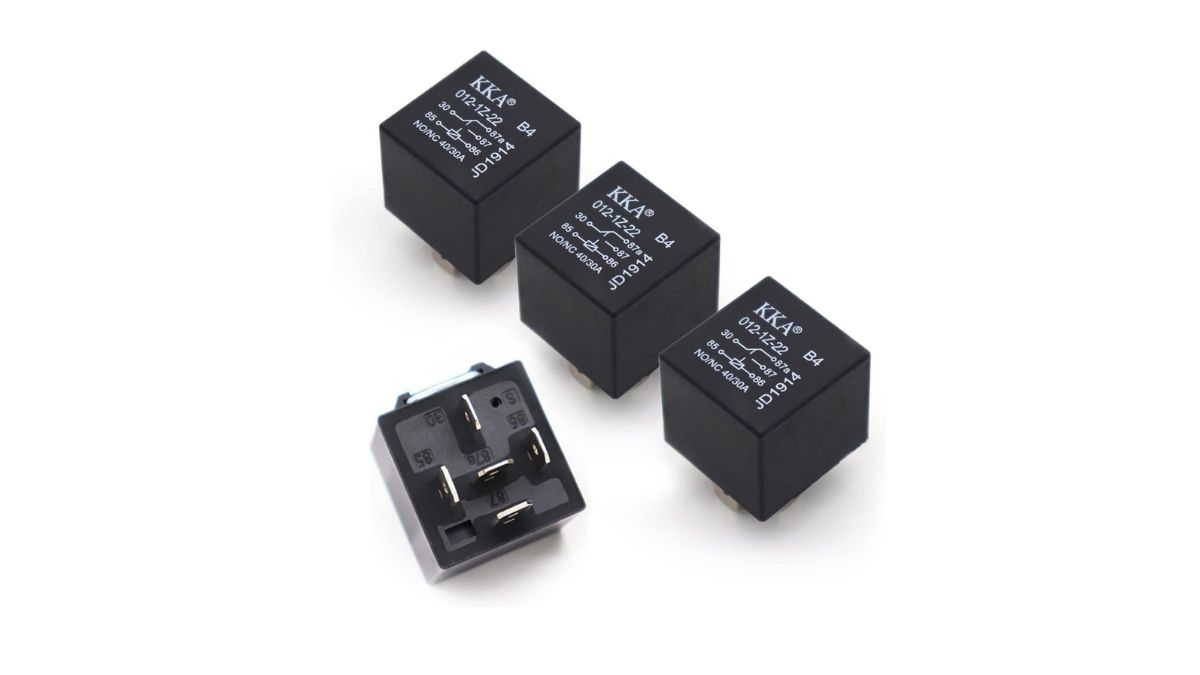
Automotive relays typically measure approximately 1 inch x 1 inch x 1.5 inches, though sizes vary from micro-relays half that size up to heavy-duty starter relays twice as large. The plastic case colors vary—black, gray, brown, blue, and other colors—with color sometimes indicating function (one manufacturer might use gray for standard relays and brown for diode-protected relays) but no universal color coding exists.
Terminal numbers appear clearly marked on the relay body, either molded into the plastic or printed on labels. Part numbers and specifications (current rating, voltage) also appear on one face of the relay. Some relays include a small diagram showing internal schematic—useful when verifying SPST vs. SPDT configuration.
The relay plugs into a socket with blade-style terminal receivers. To remove a relay, grasp it firmly between thumb and forefinger on opposite sides, then pull straight up with steady pressure. Don’t twist or rock the relay—this can bend the socket terminals. If a relay seems stuck, check whether it includes a locking tab that must be released before removal. Some relays use a separate mounting bracket or clip securing them to the fuse box—slide or lift this bracket before pulling the relay.
Before working in any fuse or relay box, always disconnect the battery negative terminal to prevent accidental short circuits. Touching a screwdriver or wrench across powered terminals creates spectacular (and damaging) sparks. Take a photo of the relay box contents before removing multiple relays—this helps ensure correct reinstallation. For additional context on the 12V battery system powering these relays, see How 12V Battery Works.
Signs of Relay Failure
Recognizing relay failure symptoms helps you diagnose electrical problems quickly and avoid unnecessary part replacement. Relays fail in several distinct ways, each producing characteristic symptoms.
Intermittent Operation represents one of the most frustrating relay failure modes. Your fuel pump runs fine for weeks, then suddenly stops—and just as mysteriously starts working again. Headlights work perfectly in cool weather but flicker or cut out when temperatures climb. Cooling fans activate sometimes but not consistently. These intermittent failures typically indicate degraded relay contacts or a failing coil winding.
Contact degradation from repeated switching cycles creates pitting and carbon buildup on contact surfaces. Initially, the contacts might make good connection when first closed, but vibration or thermal expansion can break the connection. Later, vibration might jar the contacts back together. This intermittent contact produces intermittent operation—maddeningly difficult to diagnose because the problem disappears just when you’re ready to test.
Temperature-sensitive failures often indicate coil problems. A partial short in the coil winding might conduct current when cold but fail when heated. Conversely, a cracked coil wire might expand enough to make contact when warm but open when cold. If you notice correlation between temperature and failure (always fails when hot, or always fails on cold starts), suspect thermal sensitivity in the relay.
Complete Component Failure manifests more obviously. Your headlights simply won’t turn on. The fuel pump never primes when you turn the key. The cooling fans never activate no matter how hot the engine gets. Horn doesn’t sound when you press the button. These total failures result from completely open coil windings, contacts welded in the open position, or broken armature mechanisms.
Diagnosis starts by verifying that only one component fails—if multiple components controlled by different relays all fail simultaneously, suspect a common power supply fault (blown fuse, bad ground, wiring damage) rather than multiple relay failures. Assuming a single component fails, swap its relay with an identical relay controlling a different function. If the problem moves to the other circuit, the relay has failed. If the problem stays with the original circuit, look elsewhere—fuse, wiring, or the component itself.
Audible Indicators provide valuable diagnostic clues. The relay’s click sound indicates coil energization and armature movement. Listen carefully while someone activates the system:
A single clear click when activated, plus another click when deactivated, indicates normal mechanical operation. If the component doesn’t work despite proper relay sounds, the problem lies in the power circuit—either bad relay contacts, open fuse, wiring fault, or failed component.
Rapid clicking (like a machine gun) indicates insufficient voltage reaching the relay coil or excessive current draw creating voltage collapse. The relay tries to activate, voltage drops below the holding threshold, the relay drops out, voltage recovers, the relay tries again—repeating rapidly. This pattern appears most commonly in starter circuits when the battery is nearly dead. Each time the starter relay pulls in, the massive starter current drags battery voltage down so far that the relay can’t stay engaged. The result: click-click-click-click with no starter engagement. Charge the battery and the problem disappears.
Weak clicking or buzzing sounds indicate mechanical binding or degraded magnetic force. The armature might be sticking in its bore, or the contacts might be partially welded, resisting the pull of the electromagnetic field. These sounds warn of imminent failure—replace the relay before you’re stranded.
No sound at all means either no control signal reaches the relay, the coil has failed completely open, or insufficient voltage energizes the coil. Test for battery voltage at terminal 86 and good ground at terminal 85 with the system activated.
Physical Signs of Failure:
Discolored or burnt plastic housing indicates severe overheating—likely from contacts arcing due to excessive current or degraded contact surfaces. The acrid smell of burning plastic accompanies this condition. Replace these relays immediately as they may fail catastrophically or even cause fires.
Melted plastic or warped cases result from extreme overheating—possibly a shorted component drawing excessive current through the relay, or undersized relay handling more current than its rating allows. Investigate why overheating occurred before installing a replacement—you may need a higher-rated relay or may need to repair a fault in the controlled device.
Corrosion on relay terminals appears as green or white crusty deposits. Moisture intrusion into the fuse box allows electrolysis at the copper terminals. Clean corroded terminals with electrical contact cleaner and a small wire brush, then verify proper relay seating. If corrosion recurs, investigate moisture sources—clogged cowl drains, damaged weatherstripping, or cracked fuse box housings.
Relay failure causes include:
Coil burnout from overvoltage conditions (failed voltage regulator sending 16+ volts), manufacturing defects in the coil winding (rare in quality relays), or reversed polarity in relays with integrated diodes (diode fails shorted, coil overheats).
Contact erosion from normal switching cycles accumulates over time. Each switching cycle erodes a minute amount of contact material through electrical arcing. After 50,000-100,000 cycles, contacts may lose sufficient material to compromise conductivity. High-current switching accelerates erosion—a relay switching 30 amps degrades faster than one switching 10 amps.
Mechanical failures include broken return springs (relay contacts remain closed), worn armature pivot points (sluggish operation), or contamination preventing smooth armature movement (dust, debris, corrosion products).
Environmental damage from moisture, extreme temperatures, or vibration can all compromise relay operation. Marine environments and road salt exposure accelerate corrosion. Desert heat can degrade plastic housings and dry out lubricants. Harsh off-road vibration can fatigue mechanical components or loosen terminal connections.
Testing Automotive Relays
Relay testing ranges from simple swap tests requiring no tools, through basic multimeter tests accessible to intermediate DIYers, to complex professional diagnosis needing specialized equipment. Start with the simplest tests and progress to more advanced techniques only if necessary.
Swap Test Method (Simplest Approach):
This test requires no tools and provides definitive results in five minutes. The theory is simple: if you have two identical relays in your vehicle and one controlled circuit fails, swap the suspect relay with the known-good relay. If the problem follows the relay to the new position, the relay has failed. If the problem stays at the original location, the issue lies in wiring, fuse, or the component itself.
Execute the swap test carefully. First, verify both relays are truly identical—check the part numbers molded into the relay cases. A 30-amp relay looks similar to a 40-amp relay, but they’re not interchangeable. Verify the socket pin arrangements match. Disconnect the battery negative terminal before beginning. Remove both relays by pulling straight up. Install the suspect relay in the other socket and the known-good relay in the originally problematic socket.
Reconnect the battery and test both functions. If the previously working function now fails while the previously failed function now works, you’ve confirmed relay failure. If both functions work, the relay may have intermittent failure or the issue might be elsewhere. If neither function works, you likely have a power supply or ground fault affecting both circuits.
Common relay pairs suitable for swapping include fog lights and headlights (often similar current ratings), cooling fan relays (if your vehicle has multiple fans), power window relays, or fuel pump and air conditioning compressor relays on some vehicles. Never swap a high-current relay (40A) into a low-current circuit (20A) even temporarily—the higher-rated relay fits physically but the socket terminals might not handle the potential current adequately if a fault develops.
Manual Activation Test:
With the relay installed in its socket, activate the controlled device (turn headlight switch on, press horn button, turn key to “on” for fuel pump). Place your finger on top of the relay while activating the control. You should feel a distinct click or vibration as the relay energizes—the armature snapping into position creates mechanical impulse you can feel.
If you feel the click but the device doesn’t operate, the relay coil works (proving the control circuit sends proper signals) but the power circuit has issues. The relay contacts may be bad, a fuse may be blown, wiring may be damaged, or the component itself has failed.
No felt click indicates no control signal reaches the relay, insufficient voltage energizes the coil, or the coil has failed open. Test for power and ground at the relay coil terminals with the control activated.
Multimeter Bench Testing:
Bench testing provides definitive relay evaluation. Remove the relay from the vehicle for these tests. You’ll need a digital multimeter capable of measuring resistance (ohms) and a 12V power source (a battery or benchtop power supply with alligator clip leads).
Test 1: Coil Resistance Measurement
Set your multimeter to resistance mode (Ω). Place the meter probes on terminals 85 and 86 (the coil terminals). A functional relay typically measures 50-120 ohms, though specific relays may fall outside this range. Consult relay specifications if available for exact resistance values.
An open circuit reading (OL, infinite resistance, or similar display indicating no conductivity) means the coil winding is broken. The relay cannot generate magnetic field and will never energize. Replace it.
Very low resistance (less than 10 ohms) might indicate a partially shorted coil or a non-standard relay design. Compare to specifications if possible. Suspiciously low resistance typically means impending failure even if the relay currently works.
Resistance matching your vehicle’s relay specifications confirms the coil conducts current and likely energizes properly. This test doesn’t prove the relay works, only that the coil is electrically intact.
Test 2: Contact Continuity Test (De-Energized State)
Leave the multimeter in resistance mode or switch to continuity test mode (usually produces a beep when continuity exists). Test between terminals 30 and 87 with the relay sitting on your bench, not energized.
For a normally open relay (standard SPST 4-pin), you should measure infinite resistance (open circuit, no continuity). The contacts remain separated when the coil isn’t energized, preventing current flow from terminal 30 to 87.
For SPDT 5-pin relays, test between 30 and 87a. You should measure continuity (low resistance or audible beep) because these terminals connect in the relay’s resting state. Then test between 30 and 87—should be open circuit.
If a normally open relay shows continuity between 30 and 87 when de-energized, the contacts are stuck closed or welded together. This might cause the controlled device to run continuously (fuel pump always on, cooling fan always running). Replace the relay.
If you measure open circuit where you expect continuity (30 to 87a on a 5-pin relay), the relay’s normally closed contacts have failed open—possibly corroded beyond conductivity.
Test 3: Operational Function Test
This test verifies the relay actually switches contacts when energized. You need your multimeter plus jumper wires to apply 12V to the coil terminals.
Connect your 12V source as follows: positive jumper wire to terminal 86, negative jumper wire to terminal 85. The relay should click audibly as you make the connection, indicating the coil energized and armature moved. If no click occurs, the coil has failed, insufficient voltage was applied, or mechanical binding prevents armature movement.
While maintaining 12V on the coil, measure resistance or continuity between terminals 30 and 87. You should now read continuity (low resistance) where previously you measured open circuit. The energized coil closed the contacts, creating the conductive path from 30 to 87.
Remove the 12V power. The relay should click again as the spring returns the armature to resting position. Measure 30 to 87 again—should return to open circuit (no continuity).
For 5-pin relays, test 30 to 87a with the relay energized—should read open circuit. Test 30 to 87—should read continuity. Removing power reverses these readings.
If the relay clicks properly but contacts don’t show continuity when closed, the contacts have degraded to the point of non-conductivity even when physically touching. Arcing and pitting created such high resistance that no effective electrical connection exists. Replace the relay.
Test 4: Contact Resistance (Advanced)
This test measures voltage drop across closed contacts under load, revealing degraded contacts before they fail completely. You need a multimeter capable of measuring DC voltage and a way to pass current through the closed contacts—either bench testing with a load resistor or testing in-vehicle.
Energize the relay (apply 12V to coil terminals 85/86). Measure DC voltage between terminals 30 and 87 while current flows through the closed contacts. In bench testing, connect a load resistor appropriate for the relay’s current rating between 87 and ground, with 30 connected to 12V. Measure voltage across the closed contacts (30 to 87).
Good relay contacts drop less than 0.3V when conducting rated current. Voltage drop of 0.5-1.0V indicates degraded contacts approaching end of life. Voltage drop exceeding 1.0V means severely degraded contacts that will fail soon if not immediately. This excessive resistance also generates heat (power dissipated = current² × resistance), accelerating further degradation.
Professional Diagnosis Beyond DIY Scope:
Complex electrical issues require professional diagnostic capability:
Oscilloscope testing captures voltage spike behavior during relay de-energization, verifying suppression diodes function properly and protecting computer modules.
Load testing under actual operating conditions reveals whether relays can sustain rated current without overheating or contact degradation. This requires load banks simulating actual component behavior.
Control circuit verification tests signals from body control modules, engine control units, and other computers. Professional scan tools communicate with these modules, verifying output commands and detecting internal faults.
Wiring harness integrity testing locates shorts, opens, and high-resistance faults in the complex wiring connecting relays to components and control modules. This requires professional-grade multimeters, continuity testers, and often oscilloscopes.
Critical Safety Warning: Always disconnect battery negative terminal before removing or installing relays. Never test relays with power connected to circuits unless specifically conducting in-vehicle testing. Short circuits can damage expensive modules, blow multiple fuses, or cause fires. If you’re uncomfortable with electrical testing procedures or lack appropriate test equipment, professional diagnosis is the safe choice.
For additional perspective on advanced automotive electrical diagnostics, see How Automotive Ethernet Works which covers modern high-speed vehicle network systems that increasingly integrate relay control functions.
Relay Replacement and Installation
Replacing a failed relay ranks among the simplest automotive electrical repairs. The procedure requires no specialized tools, takes minutes, and costs $10-30 for most relays. Follow proper procedures to ensure safe, reliable results.
Step 1: Identify the Correct Replacement Relay
Don’t assume all relays in your fuse box are interchangeable. Match several specifications:
Part number verification is most reliable. The failed relay has a part number molded into the plastic case or printed on a label—typically a manufacturer code like “Bosch 0 332 019 150” or an OEM number like “Ford 7L3Z-14N089-A”. Match this number exactly when purchasing a replacement. Parts store catalogs cross-reference these numbers to appropriate replacements.
If you can’t read the part number (obscured by dirt or wear), verify these specifications instead: relay type (SPST 4-pin or SPDT 5-pin), current rating (marked on the relay case as “30A”, “40A”, etc.), voltage rating (nearly always 12V for passenger vehicles), and terminal configuration (Type A or Type B layout, though this matters less if part numbers match).
Terminal pin size matters on older vehicles or aftermarket relays. Mini ISO relays use 2.8mm pins, while standard ISO relays use slightly different dimensions. Most modern vehicles standardize on mini ISO dimensions. If the replacement relay won’t seat fully in the socket or feels extremely loose, pin size mismatch may be the issue.
Purchase quality replacements from reputable manufacturers. Bosch, Tyco (TE Connectivity), Potter & Brumfield, and Omron manufacture excellent relays. OEM relays from your vehicle manufacturer cost more but guarantee correct specifications. Avoid ultra-cheap relays from unknown manufacturers—they often use inferior contact materials that fail prematurely.
Step 2: Safety Preparation
Disconnect the battery negative terminal before any electrical work. This single step prevents short circuits from dropped tools or accidental contact between powered terminals. Use a 10mm wrench or socket to loosen the negative battery terminal clamp (marked with “-” symbol or black color). Pull the cable terminal away from the battery post and secure it so it cannot accidentally contact the post.
Wait 2-3 minutes after disconnecting the battery to allow capacitors in various control modules to discharge. Some vehicle systems retain voltage briefly after battery disconnection, and this waiting period ensures all circuits are truly de-energized.
Keep tools, jewelry, and other metal objects away from the battery positive terminal (even with negative disconnected). If metal accidentally bridges positive terminal to grounded vehicle body, current flows through the metal object generating extreme heat—potentially causing burns or welding the object in place.
Step 3: Relay Removal
Locate the relay in the fuse/relay box using the diagram printed on the box cover or in your owner’s manual. Verify you’ve identified the correct relay—replacing the wrong relay won’t fix your problem and might cause a different system to fail.
Inspect the relay socket before removal. Some relays include a separate locking tab, clip, or bracket securing them to the box. Release this retention device before pulling the relay. Most relays simply press into friction-fit sockets and require no unlocking.
Grasp the relay firmly between thumb and forefinger on opposite sides (not front and back, but left and right sides). Pull straight up with steady, firm pressure. Don’t twist or rock the relay—these motions can bend the socket terminals, compromising future relay connection. If the relay resists removal, check again for locking mechanisms you’ve missed. Never use pliers or other tools that could crack the plastic case or damage terminals.
Step 4: Socket Inspection and Cleaning
With the relay removed, examine the socket terminals for corrosion, damage, or contamination. Look for green or white crusty deposits indicating corrosion, black carbon deposits from arcing, or bent terminals that won’t grip the relay pins properly.
Clean corroded terminals with electrical contact cleaner spray. This specialized solvent dissolves oxidation and contamination without leaving residue. Spray liberally into the socket, allow 30 seconds for penetration, then use compressed air to blow out dissolved contaminants. For stubborn corrosion, use a small brass wire brush or folded strip of 600-grit sandpaper to gently clean terminal surfaces.
Bent socket terminals require careful straightening. Use needle-nose pliers to gently reshape terminals to their original position—they should grip relay pins firmly without excessive force. Don’t over-bend terminals as this weakens the metal and causes cracking.
If socket damage is severe (cracked housing, broken terminals, melted plastic), the entire socket assembly or fuse box may require replacement. Professional repair is advisable for severe damage—replacing integrated fuse/relay boxes requires careful wiring work and typically costs $150-400 in parts plus labor.
Step 5: New Relay Installation
Orient the new relay correctly by matching the terminal numbers on the relay base to the socket positions. Most relay sockets include a diagram or terminal numbers molded into the plastic to guide proper orientation. Some relays include a physical keying feature (asymmetric pin arrangement or a tab) that prevents incorrect installation.
Align the relay pins with the socket receivers. The pins should center in the socket openings without forcing. Press the relay downward with firm, even pressure using both thumbs until the relay seats fully. You’ll feel the relay click into place as pins engage terminals. The relay base should sit flush against the fuse box surface with no gap.
Rock the relay gently side to side while applying downward pressure if it doesn’t seat easily. This helps align all pins simultaneously with their sockets. Don’t force—excessive force can bend pins or crack the relay case. If the relay simply won’t seat after several attempts, verify part number match and check for debris in the socket.
Some relays require reinstalling a separate bracket or clip. Slide this retention device back into position and verify it engages properly.
Step 6: Testing and Verification
Reconnect the battery negative terminal. Tighten the clamp securely—loose battery connections cause numerous electrical problems unrelated to relay function.
Test the component controlled by the replaced relay. Turn on headlights, press the horn button, turn the ignition key to “on” (for fuel pump prime), or activate the cooling fan (may require warming the engine). The component should operate normally.
Listen for proper relay click during activation and deactivation. Place your finger on the relay to feel the click if you can’t hear it clearly. Proper clicking confirms the control circuit functions and the coil energizes.
Verify full component function, not just initial activation. For example, headlights should shine brightly at full intensity, not dimly indicating high resistance in the circuit. Fuel pump should produce normal operating noise and build pressure quickly. Cooling fan should spin at expected speed.
If the component still doesn’t work after relay replacement, the problem lies elsewhere—fuse, wiring, or the component itself. Recheck the fuse for that circuit (fuses can blow during the failure that damaged the relay). Test for battery voltage at relay terminal 30 and at relay terminal 87 with the relay energized. If voltage appears at terminal 87 but the component doesn’t work, the component itself or its wiring has failed.
Replacement Selection Considerations:
Always match or exceed the original current rating. Installing a 20A relay where the circuit needs 30A guarantees rapid failure—possibly catastrophic failure with welded contacts or fire risk. Installing a 40A relay in a 30A circuit is safe (the relay is overbuilt for the application), though the larger relay might not fit the socket physically.
Consider upgrading to relays with integrated suppression diodes if the original lacked one. These cost slightly more ($2-5 premium) but better protect computer modules from voltage spikes. Verify proper polarity when installing diode-equipped relays (positive to terminal 86).
For harsh environments (marine, off-road, extreme climate), consider sealed relays with enhanced environmental protection. These cost $5-10 more but resist moisture and contaminant intrusion that causes premature failure.
When Professional Service is Recommended:
Relay replacement doesn’t fix the problem after installing a known-good relay—indicates wiring faults, component failures, or control circuit issues requiring professional diagnosis. Multiple relays fail simultaneously—suggests overvoltage condition from failed voltage regulator, requiring charging system repair. The vehicle uses integrated relay modules rather than individual plug-in relays—these modules often require programming after replacement and special tools for access.
For comprehensive understanding of the broader electrical infrastructure supporting relay operation, explore additional resources on vehicle electrical systems in the Electrical Function category.
Conclusion
Automotive relays stand as critical yet often overlooked components enabling modern vehicle electrical systems to function safely and reliably. By allowing low-current control circuits to manage devices requiring 20-40+ amps, relays protect sensitive switches and computer modules while ensuring dependable operation of essential functions from engine starting to lighting to fuel delivery. The electromagnetic switching mechanism—coil activation creating magnetic force to close high-current contacts—elegantly solves the fundamental challenge of safely controlling powerful electrical loads from protected control locations.
Understanding relay operation from electromagnetic principles through contact closure mechanisms to voltage spike suppression empowers intermediate DIY mechanics to diagnose and resolve many common electrical problems. The standardized DIN terminal numbering system (85/86 for coil circuits, 30/87/87a for power circuits) provides consistency across all vehicle makes and models, making testing and replacement straightforward with basic multimeter skills and careful attention to relay specifications.
Most relay issues manifest as clear symptoms: components that won’t operate, intermittent function, or audible clicking without activation. Simple diagnostic approaches—swap testing with identical relays, manual activation tests, or basic multimeter measurements—quickly identify failed relays. Replacement requires no special tools, costs $10-30 for most applications, and takes only minutes when following proper safety procedures. Always disconnect the battery before electrical work, match part numbers or specifications carefully, and test thoroughly after installation.
However, recognizing the limits of DIY diagnosis prevents costly mistakes and ensures safe repairs. If relay replacement doesn’t resolve the issue, the problem likely resides in wiring integrity, control signal generation, or the component itself. These situations benefit from professional electrical diagnosis with specialized equipment—oscilloscopes, load testers, manufacturer scan tools, and comprehensive wiring diagrams. Multiple simultaneous relay failures, integrated relay modules requiring programming, or vehicles with complex computer-controlled electrical architectures all warrant professional attention.
Complex modern vehicles increasingly integrate relay functions into smart power distribution modules and solid-state switching controlled by computer networks. While traditional electromechanical relays will remain standard for years to come due to their cost effectiveness and proven reliability, understanding how relay functions evolve into more sophisticated systems prepares you for emerging technologies.
Professional Consultation Is Recommended When:
- Relay swap testing proves the relay functions properly, yet the component still fails—indicating wiring faults, connector issues, or component internal failures requiring systematic diagnosis.
- Multiple relays in different circuits fail simultaneously—suggesting vehicle-wide electrical faults such as voltage regulator failure, alternator overcharging, or major ground path degradation.
- The vehicle uses integrated relay modules or body control modules incorporating relay functions—these often require scan tool programming after replacement or specialized removal procedures.
- Electrical issues accompany check engine lights, security system faults, or other computer-controlled system warnings—indicating potential network communication problems beyond simple relay switching.
- You’re uncomfortable working with electrical systems, lack proper testing equipment (multimeter minimum), or feel uncertain about diagnostic procedures—electrical problems can cause expensive damage if misdiagnosed.
For additional resources on automotive electrical systems and related components, explore the complete electrical system coverage in our Electrical Function category. For specific vehicle brand repair information and comprehensive service manuals, visit our brand manual pages to find detailed technical documentation for your vehicle make and model. And for broader exploration of all automotive systems and components, browse our extensive library of vehicle systems articles covering everything from mechanical fundamentals to advanced electronics.
Understanding how automotive relays work transforms these small black boxes from mysterious electrical components into comprehensible, serviceable parts of your vehicle’s infrastructure. Armed with this knowledge, you can tackle electrical diagnosis with confidence, save hundreds of dollars on professional labor for simple relay replacements, and better communicate with professional technicians when complex issues require expert assistance. The humble relay—using principles discovered in the 1830s to control loads that would have amazed those early pioneers—continues serving quietly but critically in every modern vehicle, making reliable electrical operation possible for millions of drivers every day.