You turn the key, and your radio goes silent. Your power windows won’t budge. The dashboard lights flicker, then die. Before you imagine expensive electrical repairs, check the simplest solution first: a blown fuse. Understanding automotive fuses—those small, often-overlooked components tucked into fuse boxes—can save you time, money, and the frustration of unnecessary dealer visits.
Automotive fuses are your vehicle’s first line of defense against electrical system damage. These sacrificial safety devices protect expensive components and prevent fires by intentionally failing when electrical current exceeds safe levels. Modern vehicles contain 40-80 individual fuses protecting everything from headlights to computer modules, with most using standardized blade-type fuses color-coded by amperage rating.
This guide explains how automotive fuses protect your vehicle’s electrical circuits, how to identify different fuse types, test them accurately with simple tools, and replace them safely without creating additional problems. You’ll learn when a blown fuse signals a simple fix versus a serious electrical issue requiring professional diagnosis.
How Automotive Fuses Protect Your Vehicle’s Electrical System
Automotive fuses function as intentional weak points in electrical circuits—they’re designed to fail so other components don’t. Inside each fuse sits a thin metal element, typically zinc or copper alloy, engineered to melt at a specific current threshold. When electrical current flowing through this element exceeds the fuse’s rating, heat builds rapidly through resistive heating (I²R losses, where current squared multiplied by resistance generates thermal energy). Within milliseconds, the element reaches its melting point, creating a gap that breaks the circuit and stops current flow completely.
This simple mechanism prevents catastrophic failures. Without fuses, a shorted power window motor could draw 50+ amperes through wiring rated for only 20 amperes. The wire would heat beyond 200°F, melting its insulation and exposing bare conductors inside door panels or dashboards—a serious fire hazard. The 20-ampere fuse protecting that circuit melts first, limiting damage to a easily-replaced component costing a few dollars rather than thousands in wiring harness replacement.
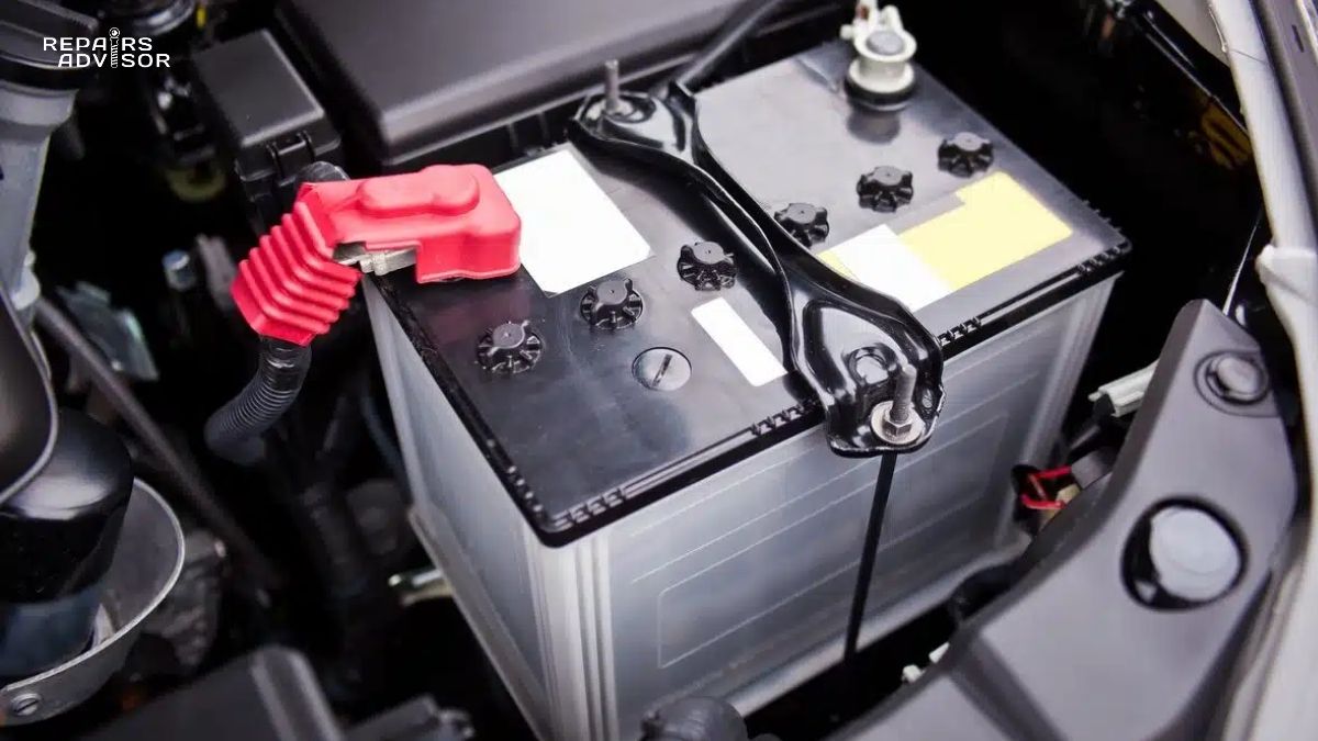
Modern automotive electrical systems operate at 12-14 volts DC, supplied by the car battery and alternator. Automotive fuses are rated for 32 volts DC—well above the system voltage to provide safety margin. Some newer vehicles with dual-voltage systems (12V/42V or 48V mild hybrid systems) use fuses rated at 42V or 58V. These voltage ratings ensure fuses can safely interrupt current without creating dangerous arcing when the element melts.
Automotive fuses come in two primary response characteristics. Fast-blow fuses respond immediately to overcurrent conditions—the dominant type for most circuits. Slow-blow or time-delay fuses tolerate brief current surges without failing, essential for motor circuits that draw high starting current. Electric window motors, windshield wipers, and HVAC blower fans can pull 2-3 times their operating current for a few seconds during startup. Time-delay fuses accommodate these normal surges while still protecting against sustained overcurrent from faults.
The protection hierarchy in vehicle electrical systems uses fuses at multiple levels. Individual circuits have dedicated fuses (radio: 10A, power windows: 20A, fuel pump: 15A), while high-current systems use larger fuses (alternator output: 120A, cooling fans: 40A). This segmented approach means a failure in your radio circuit won’t affect your headlights, and a problem with power windows won’t disable your fuel pump. Each fuse guards its specific circuit, isolating failures and preventing cascade effects that could disable entire electrical systems.
The wiring harness connects all electrical components using wire gauges matched to expected current loads. A 10-ampere circuit uses 18-gauge wire, while a 30-ampere circuit requires 10-gauge wire. Fuses protect these wires by blowing before current exceeds wire capacity. This coordination between fuse ratings and wire sizes is fundamental to automotive electrical safety—it’s why using incorrect fuse amperage is dangerous regardless of whether components seem to work.
Types of Automotive Fuses and Identification
Modern vehicles predominantly use blade-type fuses, characterized by plastic housings and two (sometimes three) metal blade terminals that plug into fuse box sockets. These standardized designs replaced older glass tube and ceramic fuses in the 1980s-1990s, offering better reliability, easier replacement, and visual status indication through transparent housings. Understanding the six main blade fuse types helps you identify correct replacements and avoid common mistakes.
Micro2 fuses (APT/ATR designation) represent the smallest blade fuse type, measuring just 9mm wide by 15mm tall. Two thin metal legs spaced closely together identify Micro2 fuses instantly. They’re most common in newer Korean-manufactured vehicles—Hyundai, Kia, and Genesis brands extensively use Micro2 fuses to maximize fuse box density in compact engine compartments. These fuses handle 5-30 ampere circuits and offer the highest circuit density per cubic inch of any blade fuse design.
Micro3 fuses (ATL designation) are the only blade fuses with three terminals instead of two—this unique feature makes identification foolproof. Measuring 14mm wide by 18mm tall, Micro3 fuses appear primarily in American full-size trucks and SUVs from Ford and General Motors. The third terminal provides redundant connection for improved reliability in high-vibration applications. Amperage ratings run 5-15 amperes for moderate-current circuits.
Low-profile mini fuses (APS designation) prioritize compact height over width—they’re shorter and wider than standard mini fuses. Two thin, widely-spaced metal legs extend just slightly from the plastic body. These fuses serve 2-30 ampere circuits and rank as the second-most common blade fuse type in modern vehicles, particularly in densely-packed dashboard fuse panels where vertical clearance is limited. Their wide, low profile maximizes fuse count in constrained spaces.
Mini fuses (APM/ATM designation) hold the title of most common automotive fuse type worldwide. Developed in the 1990s, mini fuses measure 10mm wide by 16mm tall with two thin, widely-spaced metal legs extending significantly from the housing. Nearly every passenger car built after 2000 uses mini fuses extensively throughout both engine compartment and cabin fuse boxes. They serve 2-30 ampere circuits across all vehicle electrical systems—lighting, accessories, climate control, infotainment, and more. When someone mentions “blade fuse” without specification, they typically mean mini fuses.
Standard or regular blade fuses (ATO/ATC designation) established the blade fuse format in 1976 when Littelfuse introduced the ATO design. Bussmann followed with the compatible ATC variant. Both comply with ISO 8820-3 and SAE J1284 standards. These larger blade fuses feature thick, widely-spaced metal legs and plastic bodies significantly bigger than mini fuses. They handle 1-40 ampere circuits and dominated automotive applications from the 1980s through early 2000s. Modern vehicles still use standard blade fuses for higher-current circuits (20-40A) where the larger element can safely handle sustained loads without excessive heating.
Maxi fuses (APX designation) serve heavy-duty electrical systems requiring 20-100 ampere protection. Measuring a substantial 29.2mm wide by 34.3mm tall by 8.9mm thick, maxi fuses dwarf other blade types. Their robust construction handles high currents in engine compartment applications: alternator output circuits (80-120A), electric cooling fans (40-60A), HVAC blower motors at maximum speed (30-40A), and heated windshield circuits (40-50A). Most vehicles position maxi fuses exclusively in the under-hood fuse box where their size accommodates larger electrical demands.
Before blade fuses became universal, automotive electrical systems relied on older designs still found in vintage and classic vehicles. Glass tube fuses feature cylindrical glass bodies with metal end caps, allowing visual inspection of the internal wire element. The SFE (Society of Fuse Engineers) design uses quarter-inch diameter with varying lengths by amperage—a safety feature preventing insertion of incorrectly-rated fuses. American vehicles manufactured before 1986 commonly used SFE glass fuses rated 4-30 amperes at 32 volts DC.
Bosch or torpedo fuses appear in European vehicles manufactured before 1980, particularly German cars. These ceramic or porcelain fuses measure 6×25mm with distinctive conical ends and follow DIN 72581/1 color-coding standards. Cartridge fuses like MCASE and JCASE types provide time-delayed protection for moderate to high-current circuits (15-60A), commonly protecting starter motors and other motor-driven accessories.
High-current applications require bolt-down fuses with threaded terminals and massive current-handling capability. MEGA or AMG fuses handle 60-275 amperes for starter circuits, alternator outputs, and main battery feeds. ANL fuses cover 20-500 amperes with slotted mounting ends that don’t require complete bolt removal during service. MIDI or AMI fuses offer half the size of MEGA fuses while handling 23-200 amperes—useful where packaging space is limited but high current capacity is needed.
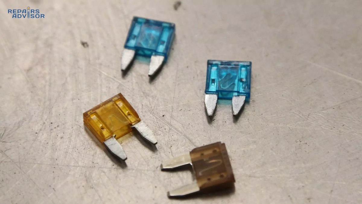
Automotive fuses follow DIN standard color coding that makes amperage identification possible at a glance. Gray indicates 2 amperes, violet marks 3A, tan designates 5A, brown shows 7.5A, red signals 10A, blue represents 15A, yellow indicates 20A, clear or white marks 25A, green shows 30A, and amber or orange identifies 40A fuses. However, manufacturers occasionally deviate from standard colors—always verify the amperage number printed on the fuse top rather than relying solely on color coding. This printed rating is definitive and legal, while color serves as a quick reference aid.
How to Test and Diagnose Blown Fuses
Identifying blown fuses quickly and accurately prevents wasted time replacing components that don’t need replacement. Three testing methods—visual inspection, multimeter continuity testing, and in-circuit voltage testing—each offer distinct advantages depending on available tools and circuit conditions.
Visual inspection works best with blade fuses and glass tube fuses where transparent plastic or glass allows direct element observation. Start by locating your vehicle’s fuse boxes—most vehicles have two primary locations. The engine compartment fuse box sits near the battery, protected by a weather-resistant cover. Open the hood and look for a black plastic box labeled “FUSE” or “FUSES” with a removable lid. The cabin fuse box typically mounts under the dashboard on the driver’s side, inside the glove compartment, or occasionally in the trunk. Consult your owner’s manual for exact locations as placement varies significantly by manufacturer and model.
Once you’ve located the appropriate fuse box, check the diagram printed on the inside cover or in your owner’s manual. This diagram maps each fuse position to its protected circuit with amperage ratings. If your radio failed, find “RADIO” or “AUDIO” on the diagram, note its position (like “F23” for fuse number 23), and locate that socket in the physical fuse box. Turn the ignition completely off and remove the key before working with fuses—this prevents accidental shorts and protects sensitive electronics.
Remove the suspect fuse using the plastic fuse puller tool usually stored inside the fuse box itself, or use clean needle-nose pliers if no puller is available. Grasp the fuse body firmly and pull straight upward with a gentle rocking motion. Avoid excessive force which can break fuse terminals or damage the socket. Once removed, hold the fuse up to a light source and look through the transparent housing. A good fuse shows an intact metal strip or wire element running continuously from one terminal to the other. A blown fuse displays a visible break or gap in this element, often with black discoloration, melted metal, or dark soot deposited inside the housing. The break might be obvious—a clear separation—or subtle—just a thin crack in the element. Any discontinuity indicates a blown fuse.
Visual inspection has limitations. Some fuses use opaque housings that prevent element observation. Heavy discoloration can obscure the element even in transparent fuses. Hairline cracks in the element might be invisible without magnification. These situations call for electrical testing rather than visual methods.
Multimeter testing provides definitive fuse status determination regardless of housing visibility. Digital multimeters with continuity testing mode deliver the fastest, clearest results. Set your multimeter to continuity mode, usually indicated by a diode symbol or radiating sound waves icon. Verify the multimeter functions correctly by touching the two probes together—the meter should emit an audible beep and display zero or very low resistance. This confirmation test ensures your equipment works before testing fuses.
Remove the fuse completely from its socket—this critical step prevents parallel current paths through vehicle wiring from giving false readings. Place one multimeter probe on each metal terminal or blade of the fuse. Polarity doesn’t matter for continuity testing. A good fuse completes the circuit, causing the multimeter to beep continuously and display 0Ω (ohms) or a reading near zero. A blown fuse shows infinite resistance: no beep, and the display shows “OL” (overload), “1” on some meters, or a blank reading. The test takes seconds and removes all ambiguity about fuse condition.
Resistance mode testing provides similar results without the audible indicator. Set the multimeter to ohms (Ω) measurement on the lowest range, typically 200Ω. Touch the probes together to verify the meter reads approximately 0Ω. Then place the probes on the fuse terminals. A good fuse reads 0-2 ohms—essentially zero resistance. A blown fuse reads OL, 1, or very high resistance values in the megaohm range. The numeric resistance reading confirms what continuity testing reveals audibly.
In-circuit voltage testing allows fuse condition checking without removal—valuable when you need to test multiple fuses quickly or when fuses are difficult to access. This method requires the circuit to be powered. Set your multimeter to DC voltage mode, selecting the 20-volt range. Connect the black (negative) probe to vehicle ground—either the negative battery terminal or any clean, bare metal bolted to the chassis. Turn the ignition to the ON position without starting the engine (called “key on, engine off” or KOEO position). This powers most vehicle electrical circuits.
Most blade fuses are designed with the terminal blade tips protruding slightly through the top of the fuse housing, allowing voltage measurement without removal. Touch the red (positive) probe to one blade tip and note the voltage—it should read approximately 12 volts (actual reading varies from 11.5-14.5V depending on battery charge and alternator operation). Now touch the red probe to the other blade tip. A good fuse shows 12 volts on both sides because current flows through the intact element. A blown fuse shows 12 volts on the supply side (connected to battery power) and 0 volts on the load side (connected to the protected component)—the broken element prevents voltage from reaching the load side. This voltage differential instantly identifies blown fuses without removal.
Blown fuses announce themselves through specific electrical symptoms. Components fail completely, not intermittently—a blown fuse breaks the circuit entirely, so affected systems won’t work at all rather than working sporadically. Multiple components on the same circuit fail simultaneously. For example, if your radio, dome lights, and power mirror controls all stop working together, they likely share a fused circuit. Dashboard warning lights sometimes illuminate when fuses blow, and some vehicles display “CHECK FUSES” messages. You might detect a brief burning odor when a fuse blows under load, though this quickly dissipates.
Common circuits affected by blown fuses include interior and dome lights, radio and infotainment systems, power windows and door locks, climate control blower fans, cigarette lighters and accessory power outlets, exterior lighting (headlights, taillights, turn signals), windshield wipers and washers, backup lights and cameras, heated seats and mirrors, and electronic safety systems. When any electrical component stops functioning, checking its fuse is the logical first diagnostic step.
Certain conditions raise red flags beyond simple fuse replacement. If the same fuse blows repeatedly after replacement, an underlying short circuit or component failure is causing overcurrent—the fuse is doing its job by protecting the system from a genuine fault. Don’t keep replacing the fuse hoping it will hold; have the circuit professionally diagnosed to find the root cause. Multiple unrelated fuses blowing simultaneously suggests serious electrical problems like wiring harness damage or ground system failures. A new fuse that sparks or blows instantly upon installation indicates an active short to ground requiring immediate professional attention.
Safe Fuse Replacement Procedures and Critical Safety Requirements
Replacing automotive fuses correctly requires attention to specifications and proper technique. The process itself is simple, but mistakes carry serious consequences—electrical damage, fire hazards, or component failures costing hundreds to thousands of dollars.
Begin by turning the vehicle completely off and removing the key from the ignition. This de-energizes most electrical circuits and prevents accidental shorts or computer system resets during fuse handling. For maximum safety, especially when working with high-current fuses in the engine compartment, disconnect the negative battery terminal. This eliminates all electrical power and protects both you and vehicle electronics from accidental damage. While not always necessary for simple cabin fuse replacement, battery disconnection is recommended for engine compartment work near automotive relays and high-current circuits.
Gather the correct replacement fuse before starting work. This means identifying the exact fuse type (Micro2, Mini, Standard, etc.) and amperage rating. Check your owner’s manual for the fuse box diagram showing each circuit’s specifications. The amperage rating is printed on top of every blade fuse—look for numbers like “10A” or “20A” embossed in the plastic housing. Purchase exact-match replacement fuses from auto parts stores, dealerships, or online suppliers. Quality matters—cheap aftermarket fuses may use inferior metals that don’t fail at rated currents or create high resistance connections. Stick with name brands like Littelfuse, Bussmann, or manufacturer-original parts.
Identify the blown fuse using the fuse box diagram. Fuse boxes contain 20-60 individual fuses arranged in rows with numbered positions. The diagram correlates position numbers with circuits and amperage—position F14 might be “RADIO – 10A” while F27 shows “PWR WINDOW – 20A.” Locate the position physically in the fuse box. Most fuse boxes include a fuse puller tool stored in a clip inside the cover or box housing—retrieve this tool before proceeding.
Grasp the fuse firmly with the fuse puller or clean needle-nose pliers. The puller typically has a small plastic fork that clamps the fuse sides. Pull straight upward with steady pressure while rocking the fuse gently side to side. Blade fuses seat with friction fit, so some resistance is normal. Avoid yanking or using excessive force that might break terminals or damage the fuse box socket. The fuse should slide free after a few millimeters of upward travel. Set the removed fuse aside for inspection—confirming it’s actually blown prevents replacing good fuses unnecessarily.
Before installing the replacement, perform a critical verification step that many DIYers skip: confirm the new fuse matches the old fuse in every specification. Check the amperage rating printed on top—it must exactly match the original. Verify the fuse type and size—a Mini fuse won’t fit in a Standard fuse socket, and forcing incompatible fuses damages both fuse and socket. Confirm the voltage rating if dealing with dual-voltage systems or high-voltage hybrid components (standard automotive fuses are 32V; some applications require 42V or 58V rated parts).
Align the replacement fuse with the socket, ensuring the blade terminals line up with the socket slots. The fuse orientation doesn’t matter electrically—blade fuses work in either direction. Push down firmly and evenly on the fuse body until it seats completely flush with adjacent fuses. The fuse should require moderate pressure to install but shouldn’t need hammering or extreme force. Once seated, the fuse should be secure and not pull out with light finger pressure. If the fuse wobbles or pulls out easily, the socket contacts may be damaged and require professional repair.
Reconnect the battery negative terminal if you disconnected it, then turn the ignition to ON position. Test the affected electrical component immediately. If the radio wasn’t working and you replaced its fuse, turn on the radio. If it operates normally, the replacement succeeded—the blown fuse was likely caused by age or a transient power surge. If the component still doesn’t work, you may have identified the wrong circuit, or additional problems exist beyond the fuse. If the new fuse blows immediately or within seconds of installation, stop the replacement process—an active electrical fault is present that requires professional diagnosis.
The single most critical safety rule in fuse replacement is amperage accuracy. Never, under any circumstances, install a higher-amperage fuse than specified for the circuit. This practice seems logical to DIYers frustrated by repeatedly blown fuses—”I’ll just put in a 30A fuse instead of a 20A to stop the blowing.” This creates extreme danger. Circuit wiring and components are engineered for specific current loads. A 20-ampere circuit uses wire gauge rated for 20 amperes continuous current with safety margin. Installing a 30-ampere fuse allows 30 amperes to flow before the fuse blows—but the 20-ampere-rated wire overheats at 25+ amperes. The wire insulation melts, exposing bare conductors that short against metal body panels or nearby wires, starting electrical fires that can total vehicles or cause injuries.
Conversely, installing lower-amperage fuses than specified causes nuisance blowing—components won’t operate reliably. A 30-ampere circuit protected by a 20-ampere fuse will blow during normal operation when current demand exceeds 20 amperes. The component appears defective when actually the fuse rating is wrong. Always use the exact amperage specified in the fuse box diagram or owner’s manual. No exceptions.
Never attempt makeshift fuse repairs using aluminum foil, copper wire, paper clips, or other conductive materials. This dangerous practice bypasses all overcurrent protection—the very purpose of fuses. Stories circulate about wrapping blown fuses in foil “to get home” or using wire as temporary fuses. These makeshift conductors don’t melt at safe current levels; they allow unlimited current flow until wiring catches fire or components explode. The “emergency” repair that gets you home might burn your car to the ground instead. If you’re stranded with a blown fuse, call for a tow or buy correct replacement fuses at the nearest auto parts store. Never bypass fuse protection under any circumstances.
Safe handling practices reduce injury and damage risks. Keep hands dry when working with electrical components—moisture conducts electricity and increases shock potential. Wear safety glasses to protect eyes from potential sparks, particularly when working with engine compartment high-current fuses. Avoid touching fuse box components or terminals while the engine runs—moving belts and hot surfaces present mechanical and thermal hazards, while live electrical components carry shock risks. Keep a supply of common spare fuses (5A, 10A, 15A, 20A, 30A) in your vehicle for roadside repairs and emergencies.
Certain situations demand professional diagnosis rather than continued DIY fuse replacement. If the same fuse blows two or more times after replacement, an underlying short circuit or component failure is present—continued fuse replacement won’t solve the problem and wastes money on fuses. Multiple fuses blowing simultaneously indicates serious electrical system problems like damaged wiring harnesses or failed power distribution modules. Burning smells from electrical components or fuse boxes signal insulation damage or component overheating requiring immediate professional attention.
Visible wiring damage—melted insulation, exposed conductors, corroded connections—needs professional repair before normal fuse service will work. Electrical malfunctions that persist after correct fuse replacement suggest problems beyond circuit protection. Modern vehicles with complex electronic systems often require diagnostic scanners to identify faults properly—professional technicians have equipment to test load currents, trace short circuits through wiring bundles, and diagnose computer-controlled electrical systems that DIY methods can’t reach.
Professional automotive electrical technicians bring specialized capabilities to complex problems. They perform electrical system load testing to identify circuits drawing excessive current. They use short circuit tracers that inject signals into wiring and detect them with probes, pinpointing the exact location of shorts in bundled harnesses containing dozens of wires. They inspect wiring harnesses throughout the vehicle, identifying damaged sections that need repair or replacement. They test individual components with dedicated equipment to isolate faulty parts—failed window motors, shorted climate control modules, damaged lighting assemblies. They use factory scan tools to diagnose computer-controlled electrical systems and retrieve diagnostic codes from electronic control modules.
When electrical problems exceed simple fuse replacement, professional diagnosis prevents expensive parts replacement guessing games and ensures safe, reliable repairs. The cost of professional electrical diagnosis ($100-200 typically) saves money compared to blindly replacing components hoping to fix mysterious electrical issues.
Conclusion
Automotive fuses protect your vehicle’s electrical system through elegant simplicity—sacrificial metal elements that melt before expensive components suffer damage. Modern blade-type fuses (Micro2, Micro3, Mini, Low-Profile Mini, Standard, and Maxi varieties) provide reliable, visible circuit protection across 40-80 individual circuits in typical vehicles. Color coding and amperage markings enable quick identification, while transparent housings allow visual condition assessment.
Testing blown fuses requires only basic tools and techniques. Visual inspection through transparent housings reveals broken elements in most cases. Multimeter continuity testing provides definitive electrical confirmation of fuse condition regardless of visibility. In-circuit voltage testing identifies blown fuses without removal, speeding diagnosis when checking multiple circuits. Recognizing blown fuse symptoms—complete component failures, multiple simultaneous failures, and dashboard warnings—helps you diagnose electrical problems quickly.
Safe fuse replacement demands exact amperage matching and proper installation technique. Turn off the vehicle, identify the correct fuse from diagrams, remove the blown fuse carefully, verify replacement specifications match exactly, install the new fuse completely, and test component operation immediately. Never install higher-amperage fuses than specified, never use makeshift repairs with foil or wire, and never continue replacing fuses that blow repeatedly without diagnosing underlying faults.
Understanding automotive fuses empowers you to resolve common electrical failures independently while recognizing when professional diagnosis becomes necessary. Keep spare fuses in your vehicle (5A, 10A, 15A, 20A, 30A cover most circuits) for roadside repairs and unexpected failures. When fuses blow repeatedly, multiple circuits fail, or electrical problems persist after correct fuse replacement, consult certified automotive technicians with proper diagnostic equipment. Smart fuse knowledge saves money on simple fixes while protecting you from the dangers of incorrect repairs on complex electrical systems.
Your vehicle’s fuse boxes contain the first line of defense against electrical system damage. Knowing how to diagnose and replace fuses safely keeps you mobile, prevents expensive repairs, and maintains the reliability of modern automotive electronics. Take a few minutes to locate your vehicle’s fuse boxes, review the diagrams, and familiarize yourself with the fuse types used—this knowledge pays dividends the first time an electrical component fails unexpectedly.