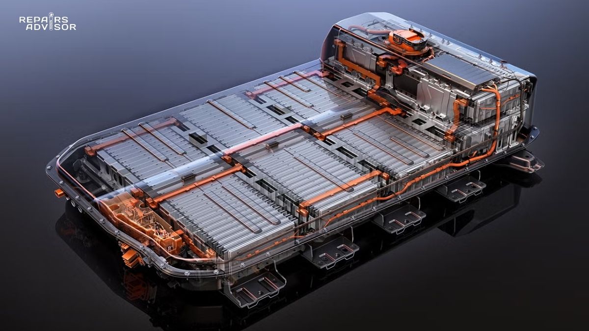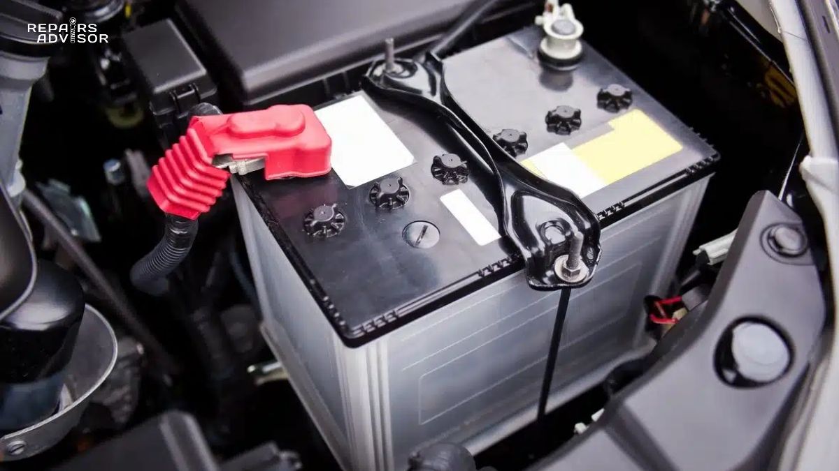
The alternator is your vehicle’s electrical power plant, converting mechanical energy from the engine into electrical energy to power all vehicle systems and continuously recharge the battery. While the battery provides starting power, the alternator supplies 100% of the electrical power needed during engine operation—running ignition systems, fuel injection, lights, climate control, entertainment systems, and all vehicle computers. Without a working alternator, your vehicle will run only until the battery is depleted, typically 20-60 minutes depending on electrical load.
Car alternator operation generates alternating current (AC) through electromagnetic induction, then converts it to direct current (DC) through internal rectifier diodes. Modern alternators produce 13.5-14.8 volts during normal operation, with alternator output capacity ranging from 60 amps on small economy cars to 200+ amps on large trucks and luxury vehicles with extensive electrical systems. The voltage regulator, either internal or external, constantly adjusts alternator voltage regulation to match electrical demand while preventing battery overcharging—overcharging can damage the battery and electrical components, while undercharging depletes the battery and causes system failures.
Alternator failure leaves you stranded and can cause expensive secondary damage. Common failure symptoms include dimming headlights, slow power window operation, dashboard warning lights (battery or charging system), unusual noises from the alternator area (grinding or whining), burning smell from overheated components, electrical system malfunctions, difficulty starting, and battery warning indicators. A completely failed alternator will eventually cause the engine to stall when the battery cannot provide sufficient power for ignition and fuel injection. Partially failed alternators may provide insufficient alternator output, slowly draining the battery and causing intermittent electrical problems.
Safety Note: Alternator testing and replacement require working near moving engine belts and electrically live components. Never touch alternator components while the engine is running. Incorrect alternator connections can damage sensitive electronics or create fire hazards. If you experience charging system problems, have your vehicle professionally diagnosed—modern vehicles require specialized diagnostic equipment to properly test alternator function and charging system operation. For comprehensive guidance on how car batteries work and their interaction with the charging system, understanding both components is essential for diagnosing electrical issues.
Alternator Parts and Construction Explained
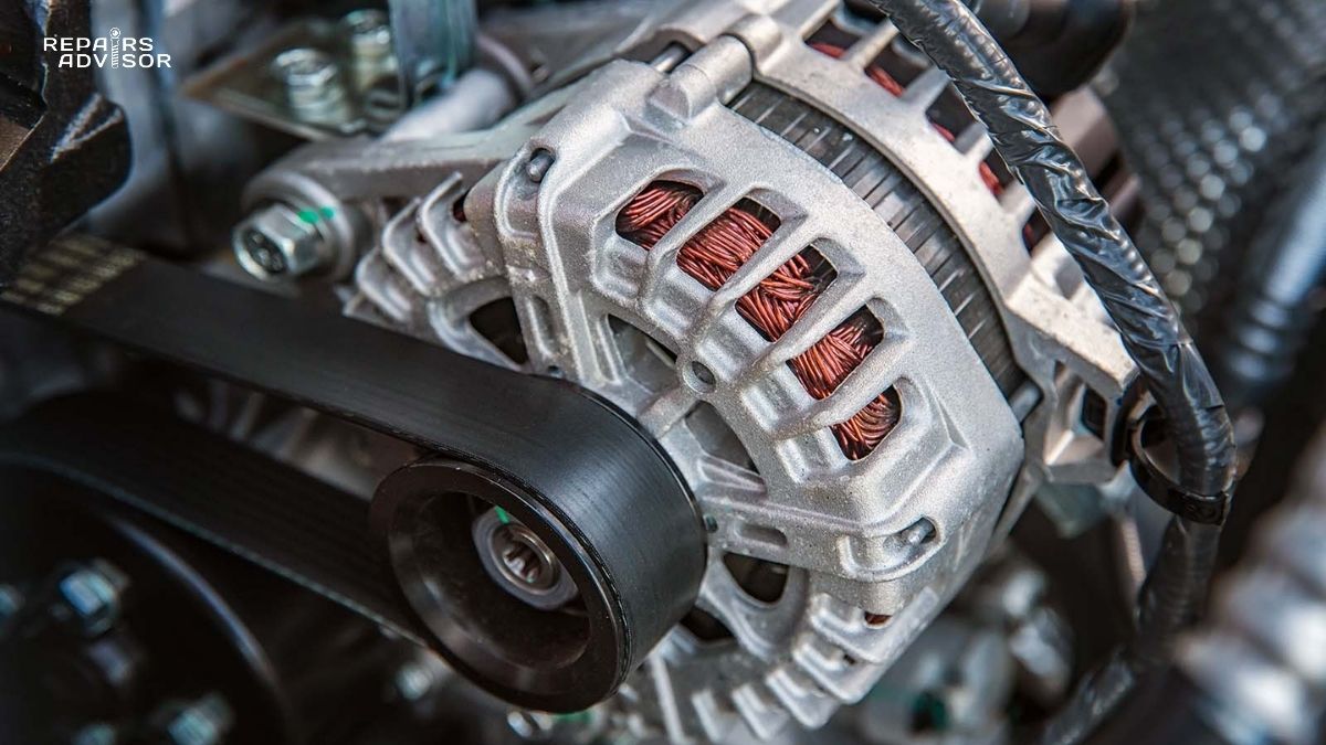
An alternator assembly consists of a cast aluminum housing containing a rotating electromagnetic rotor, stationary stator windings, rectifier bridge, voltage regulator, cooling fan, and drive pulley—all integrated into a compact, reliable package weighing 10-25 pounds. Understanding alternator components reveals how this device generates electrical power.
Rotor Assembly (Field Coil):
The rotor is a cylindrical electromagnet at the center of the alternator, connected to the drive pulley and spinning at engine speed. It consists of a field coil (many turns of copper wire wrapped around an iron core) and interlocking steel pole pieces shaped like fingers that surround the coil. Two slip rings at the rotor’s rear end receive DC current through stationary carbon brushes, energizing the field coil to create a rotating magnetic field. The rotor spins at 2-3 times engine speed (via pulley ratio), typically 2,000-6,000 RPM during normal driving and up to 12,000 RPM at high engine speeds.
Stator Assembly (Output Windings):
The stator is a stationary ring of iron laminations surrounding the rotor, containing three separate sets of copper wire windings positioned 120 degrees apart. As the rotor’s magnetic field spins inside the stator, it induces three-phase alternating current in the stator windings through electromagnetic induction. This is the fundamental alternator function—converting rotational motion into electrical current. The stator is rigidly mounted inside the alternator housing and generates the alternator output that powers the vehicle.
Rectifier Bridge (Diode Pack):
The rectifier assembly consists of six power diodes arranged in a bridge configuration to convert three-phase AC from the stator into DC current suitable for the vehicle’s electrical system and battery charging. Diodes act as one-way electrical valves, allowing current flow in only one direction. The rectifier must handle the full alternator output current, which can exceed 150 amps in high-output units. Heat sinks or cooling fins dissipate the heat generated during rectification. Failed diodes are a common alternator failure mode, reducing alternator output and causing AC ripple in the DC output.
Voltage Regulator:
The voltage regulator is a solid-state electronic control unit that monitors battery voltage and adjusts field coil current to maintain proper alternator voltage regulation—typically 13.5-14.8 volts. Modern internal regulators are integrated into the alternator housing, while some older vehicles used external regulators. The regulator continuously varies field current based on electrical load and battery state of charge: heavy electrical loads or low battery voltage trigger higher field current for increased output, while light loads and fully charged batteries reduce field current to prevent overcharging. Advanced smart charging systems communicate with the vehicle’s ECU to optimize alternator operation for fuel economy and battery health. Understanding how voltage regulators work provides deeper insight into this critical control system.
Drive System and Cooling:
A multi-groove serpentine belt connects the alternator pulley to the engine crankshaft, transmitting mechanical power to drive the alternator. The pulley ratio typically causes the alternator to spin 2-3 times faster than engine speed—for example, 6,000 alternator RPM when the engine runs at 2,000 RPM. An internal cooling fan, cast as part of the rotor assembly, pulls air through the housing to dissipate heat generated by electrical resistance in windings and diodes. Proper cooling is essential—alternators can generate 500-1,000 watts of waste heat under full load. The drive belt tensioner system maintains proper belt tension for efficient power transmission.
Bearings and Brushes:
Precision ball bearings at front and rear of the rotor shaft allow smooth, low-friction rotation at high speeds. These bearings are sealed and lubricated for long service life but eventually wear, causing noise and play. Carbon brushes make sliding contact with slip rings to conduct current to the rotating field coil. Brush wear is gradual and normal—most brushes last 100,000-150,000 miles, though they can be replaced during alternator rebuild.
Quality Variations:
OEM alternators from manufacturers like Bosch, Denso, Valeo, and Mitsubishi feature precision-balanced rotors, high-quality bearings, robust rectifier diodes, and comprehensive voltage regulation. They’re engineered for specific vehicle electrical loads and mounting configurations. Remanufactured alternators offer good value, with new bearings, brushes, and voltage regulators installed in tested cores. Budget new alternators may have lower-quality components with shorter service life. High-performance alternators provide increased alternator output (150-300+ amps) for vehicles with aftermarket electrical accessories like large audio systems or off-road lighting.
How Alternator Works: Step-by-Step Operation
The car alternator operation transforms rotational mechanical energy from the engine into electrical energy through electromagnetic induction, voltage regulation, and AC-to-DC conversion—a continuous process occurring whenever the engine runs. Understanding how alternator components work together reveals the sophisticated electromechanical engineering behind this essential device.
Step 1: Initial Excitation and Magnetic Field Creation
When you start the engine, initial field current must energize the alternator’s rotor before it can generate output. This initial excitation current comes from the battery through the ignition switch and alternator warning light. Approximately 2-5 amps of DC current flows through the carbon brushes into the rotor’s slip rings, energizing the field coil wrapped around the rotor core. This current creates an electromagnetic field around the rotor—turning it into a powerful spinning magnet. Once the alternator begins generating output, it becomes self-sustaining, using a small portion of its own output to maintain the field current. This is why the alternator warning light on your dashboard goes out once the engine starts—the alternator has taken over supplying its own excitation current.
Step 2: Electromagnetic Induction and AC Generation
As the engine runs, the crankshaft drives the serpentine belt, which turns the alternator pulley and rotor shaft. The rotor’s magnetic field spins at high speed inside the stationary stator windings. As the north and south magnetic poles of the rotor pass by each stator winding, they induce alternating current in the copper wires through electromagnetic induction—the same principle used in massive power plant generators. The three stator windings are positioned 120 degrees apart, creating three-phase AC power. Each winding produces a sine wave of voltage, with peaks occurring twice per rotor revolution. The three-phase design is highly efficient—at any given moment, at least one phase is producing near-peak output. The frequency of the AC varies with engine speed (400-600 Hz at highway speeds), but this isn’t a problem because the alternator converts everything to DC anyway. The relationship between how ignition systems work and alternator power delivery highlights the interconnected nature of vehicle electrical systems.
Step 3: AC to DC Conversion (Rectification)
The rectifier bridge contains six diodes arranged in a three-phase, full-wave bridge configuration. As AC current alternates positive and negative in the stator windings, the diodes route current to ensure it flows in only one direction to the output terminal. The three-phase design is efficient—at any given moment, at least one phase is producing near-peak output, resulting in relatively smooth DC with minimal ripple. This rectified DC becomes the alternator output that powers all vehicle electrical systems. The diodes must withstand substantial current and heat—in a 150-amp alternator operating at full output, the diodes handle tremendous electrical stress.
Step 4: Voltage Regulation and Output Control
Without voltage regulation, alternator output would increase with engine speed, potentially reaching 30-40 volts at high RPM—destructive to electrical components and the battery. The voltage regulator continuously monitors battery voltage and modulates field coil current to maintain constant alternator voltage regulation regardless of engine speed or electrical load. When battery voltage drops below the setpoint (typically 13.8-14.4 volts), the regulator increases field current, strengthening the rotor’s magnetic field and increasing output. When voltage rises above the setpoint, the regulator reduces or switches off field current, weakening the magnetic field and decreasing output. This switching occurs hundreds of times per second, maintaining stable voltage output. Modern smart charging systems vary this target voltage based on battery temperature, state of charge, and electrical load—for example, allowing slightly higher voltage immediately after starting to quickly recharge the battery, then reducing voltage during highway driving for fuel economy.
Step 5: Load Response and Power Distribution
The charging system continuously balances two loads: maintaining battery charge and powering all operating electrical systems. When electrical loads increase—headlights activated, heater blower running, rear window defogger operating—the alternator output current increases to meet demand. The voltage regulator senses the slight voltage drop caused by increased load and raises field current to compensate, maintaining steady system voltage. The battery acts as an electrical buffer, absorbing excess current when generation exceeds demand and supplying additional current during peak loads that exceed alternator output capacity. During starting, the starter motor may draw 150-300 amps, far exceeding any alternator’s output—the battery provides this surge, and the alternator then recharges it during subsequent driving.
Step 6: Thermal Management and Protection
Alternators generate substantial heat during operation—electrical resistance in windings and diodes converts some energy to heat rather than electrical output. The internal cooling fan continuously pulls air through ventilation slots in the housing, flowing it over the stator windings, rectifier heat sinks, and regulator components. At high outputs or in hot engine compartments, alternators can reach internal temperatures exceeding 200°F. The voltage regulator monitors temperature and may reduce output to prevent damage during extreme conditions—this thermal derating prevents component failure but reduces alternator output capacity. Some high-performance applications use alternators with external cooling fans or liquid cooling to maintain full output in harsh conditions.
Real-Time System Integration
Modern alternators integrate with the vehicle’s computer systems through digital communication. The ECU may command the alternator to reduce output during acceleration (reducing parasitic drag for better performance), increase output during deceleration (using engine braking to generate electrical energy), or modulate output for optimal fuel economy. Some systems monitor individual electrical loads and predictively adjust alternator output. In hybrid vehicles, the high-voltage system’s DC-DC converter often supplements or replaces traditional alternator function. Advanced stop-start systems require special alternators with reinforced bearings and components to handle frequent restarts. The alternator also powers the vehicle’s computer network, including critical safety systems like ABS, stability control, and airbag computers—highlighting why alternator function is truly critical for vehicle operation and safety. Understanding how automotive relays work helps explain how the alternator’s power is distributed throughout the vehicle’s wiring harness system.
Alternator Location and Access Guide
The alternator is typically mounted on the front of the engine, driven by the serpentine accessory belt from the crankshaft pulley. On most vehicles, it’s located on the passenger side or driver side of the engine, positioned toward the upper front corner for belt accessibility. You can identify it by looking for a cylindrical or oval metal housing about 5-7 inches in diameter, typically aluminum with cooling fins, with a ribbed pulley on the front and electrical connections at the rear.
Visual Identification:
The alternator is visually distinctive: a substantial cylindrical housing with a multi-groove pulley on the front end driven by the serpentine belt, a large output wire (typically 6-8 gauge) connecting to the positive battery or fuse box, and a smaller wire connector for voltage regulator communication. Most alternators display output ratings on a label—for example, “14V 120A” indicates 14-volt output with 120-amp capacity. The alternator moves when you manually press on the serpentine belt, unlike fixed components. On the rear, you’ll see ventilation slots for cooling and the electrical connection terminals.
Access Requirements:
Intermediate DIY mechanics can access the alternator for inspection and replacement on many vehicles. Basic access requires opening the hood and visually locating the alternator. For removal, you’ll need to disconnect the battery negative terminal first, release serpentine belt tension, disconnect electrical connections, remove mounting bolts (typically 2-4 bolts), and extract the alternator. Required tools include socket sets, serpentine belt tool or breaker bar for tensioner release, and electrical connection tools. Testing alternator function requires a digital multimeter to measure voltage output and charging performance.
Vehicle Configuration Variations:
Front-engine, rear-wheel-drive vehicles usually provide excellent alternator access on the engine sides. Front-wheel-drive vehicles with transversely mounted engines sometimes position the alternator deep in the engine bay, requiring removal of other components for access—plastic engine covers, air intake ducts, or even cooling fans might need removal first. Some vehicles mount the alternator low on the engine, requiring access from underneath. Trucks and SUVs with large engine bays typically provide easy alternator access. Hybrid vehicles may have conventional alternators for 12-volt systems or may use integrated starter-generators requiring professional service.
Professional Service Considerations:
While alternator replacement is within the capability of intermediate DIY mechanics, proper diagnosis requires professional equipment. A complete charging system test includes measuring alternator output at various loads and engine speeds, testing voltage drop in charging system wiring, evaluating battery condition using proper procedures, checking for AC ripple in DC output (indicating failed diodes), and testing voltage regulator function under varying conditions. Incorrect alternator installation can damage vehicle electronics—proper electrical connections and belt tension are critical. Some modern vehicles require alternator registration or programming after replacement, necessitating professional diagnostic tools.
For vehicle-specific service procedures, consult repair manuals matched to your exact make and model. Ford repair manuals, Toyota service documentation, Chevrolet technical guides, and Honda repair procedures provide manufacturer-specific instructions for alternator service and charging system diagnostics.
Safety Considerations:
Always disconnect the battery negative terminal before working on the alternator—the output terminal is always electrically live when connected. Never disconnect alternator connections while the engine is running, as this can cause voltage spikes that damage electronic components. The serpentine belt area is dangerous—keep hands, tools, and clothing away from moving belts and pulleys when the engine runs. Alternators are heavy (15-25 pounds) and awkwardly shaped—secure them before removing mounting bolts to prevent dropping. If you’re uncomfortable working with electrical systems or lack proper diagnostic equipment, professional service ensures correct diagnosis and safe repair.
Common Alternator Failure Symptoms and Diagnosis
Recognizing alternator failure symptoms early can prevent being stranded and avoid secondary damage to electrical components. Dimming or flickering headlights, especially at idle or when electrical accessories activate, indicate insufficient charging system output. The dashboard battery warning light typically illuminates when alternator output drops below acceptable levels—despite the battery symbol, this light often signals alternator problems rather than battery issues. A dead or weak battery requiring frequent jump-starts may result from a failing alternator that cannot maintain proper charge.
Electrical accessories malfunctioning—slow power windows, radio cutting out, weak air conditioning—suggest inadequate power supply from a failing alternator. Unusual noises from the alternator area, including whining, grinding, or squealing sounds, often indicate worn bearings or damaged internal components. A burning smell near the alternator warns of overheated components or a slipping serpentine belt. Engine stalling while driving, particularly if preceded by other electrical symptoms, occurs when the battery depletes and cannot provide ignition and fuel injection power. Difficulty starting the vehicle even with a jump-start points to charging system problems rather than just a worn battery.
Quick Diagnostic Checks:
Testing alternator output requires a digital multimeter. With the engine off, a healthy battery should measure 12.6-13.2 volts at the terminals. Start the engine and let it idle—voltage should increase to 13.5-14.8 volts, indicating the alternator is charging. If voltage remains at 12.6 volts or lower with the engine running, the alternator is not charging properly. Turn on electrical loads (headlights, heater blower, rear defogger) and observe voltage—it should remain above 13.5 volts. Significant voltage drop under load indicates weak alternator output.
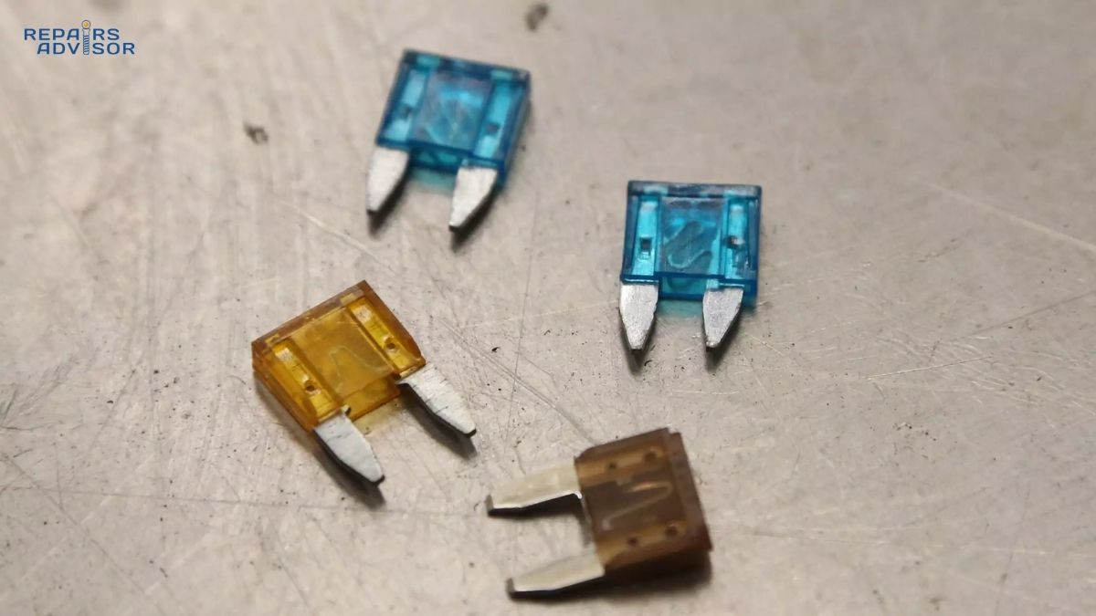
Visual inspection reveals many alternator problems. Check serpentine belt condition—cracks, glazing, or fraying indicate replacement needed. Loose belt tension causes slipping, reducing alternator output and creating squealing noise. Inspect electrical connections at the alternator—corrosion or loose connections prevent proper charging. Look for physical damage to the alternator housing, leaking fluids, or burnt electrical connections. Understanding how automotive fuses work helps diagnose whether electrical problems stem from the alternator or blown fuses in the charging circuit.
Battery vs Alternator Diagnosis:
Determining whether the battery or alternator is failing requires systematic testing. Jump-start the vehicle and immediately disconnect the jumper cables. If the car dies within a few minutes, the alternator is not providing sufficient charge. If the car continues running normally, the battery likely needs replacement but the alternator is functioning. However, a severely degraded battery may fail even with a working alternator—professional load testing provides definitive diagnosis. Many auto parts stores offer free alternator and battery testing, using specialized equipment to assess both components under realistic load conditions.
Replacement Cost and Options:
Alternator replacement costs vary significantly based on vehicle type and parts selection. DIY alternator replacement, purchasing parts only, typically costs $100-$500 depending on vehicle make, model, and alternator specifications. Professional installation adds $100-$300 in labor charges, bringing total professional replacement costs to $450-$1,000 or more. Luxury vehicles, hybrid systems, and difficult-to-access installations increase costs substantially. Remanufactured alternators offer cost-effective alternatives to new OEM units, typically costing 30-50% less while including warranties. These rebuilt units feature new bearings, brushes, voltage regulators, and rectifiers installed in tested cores. High-output alternators, required for vehicles with extensive aftermarket electrical accessories (audio systems, off-road lighting, winches), cost more but prevent charging system overload.
Conclusion
The alternator serves as your vehicle’s electrical power plant, operating continuously whenever the engine runs to power all electrical systems and maintain battery charge. This sophisticated electromechanical device converts mechanical rotation into electrical energy through electromagnetic induction, precisely regulated to provide stable voltage regardless of engine speed or electrical demand. Understanding how the rotor, stator, rectifier bridge, and voltage regulator work together reveals the engineering sophistication underlying this essential component.
Modern alternators integrate seamlessly with vehicle computer systems, optimizing output for fuel economy while ensuring critical safety systems receive uninterrupted power. The alternator powers not just obvious electrical loads like lights and accessories, but also critical systems including engine management, fuel injection, ABS, stability control, and airbag computers. Regular attention to warning signs—dimming lights, unusual noises, dashboard warnings—enables early detection of alternator problems before complete failure leaves you stranded.
When charging system problems arise, professional diagnosis using specialized test equipment provides accurate assessment of alternator function, battery condition, and wiring integrity. Modern vehicles often require programming or registration after alternator replacement, making professional service advisable for complex systems. Whether you choose DIY replacement or professional service, understanding alternator operation helps you make informed decisions about charging system maintenance and repair.
For comprehensive vehicle-specific service procedures, electrical system troubleshooting, and detailed technical specifications, consult professional repair manuals matched to your exact vehicle make, model, and year. These resources provide the manufacturer-specific information needed for successful alternator service and charging system maintenance. Visit our automotive repair category for additional electrical system guidance and component information.