Bottom Line Up Front: Starting a car requires four critical wire categories: battery cables (power supply), starter motor wiring (high-current circuit), ignition switch wiring (control signals), and engine control wiring (sensors and fuel systems). While you might theoretically start a car with just two wires in an emergency, a properly functioning starting system relies on multiple interconnected circuits working together safely and reliably.
Understanding your vehicle’s starting system wiring isn’t just about getting your car running—it’s about ensuring safe, reliable operation and being able to diagnose problems before they leave you stranded. Whether you’re a DIY enthusiast looking to expand your automotive knowledge or a professional technician brushing up on fundamentals, this comprehensive guide will walk you through everything you need to know about the wires that bring your engine to life.
Understanding Your Car’s Starting System Basics
Your car’s starting system is an intricate network of electrical circuits that work together to transform battery power into the mechanical energy needed to crank your engine. At its core, this system involves a sophisticated dance between multiple electrical components, each connected by specific wires designed to handle different voltage and current requirements.
The starting process begins when you turn your ignition key or press the start button, sending a low-current signal through control wires to activate high-current circuits. This signal energizes the starter solenoid, which closes heavy-duty contacts that allow battery power to flow through thick cables to the starter motor. Simultaneously, other circuits ensure your engine management system is ready to provide fuel and ignition timing.
Modern vehicles have evolved far beyond the simple starter systems of decades past. Today’s starting circuits integrate with anti-theft systems, engine control modules, and various safety interlocks. However, the fundamental wiring principles remain consistent: power must flow from the battery through control circuits to activate the starter motor while simultaneously preparing engine management systems for operation.
The electrical current flow during starting follows a predictable path: from the positive battery terminal through heavy gauge cables to the starter motor, while control circuits simultaneously signal various engine systems to prepare for operation. Understanding this flow helps diagnose problems and ensures safe working practices when servicing starting systems.nt performance.
Essential Safety Considerations Before Working on Car Wiring
CRITICAL SAFETY WARNING: Automotive electrical work involves risks including electrical shock, fire, explosion, and damage to expensive electronic components. Always prioritize safety over convenience, and never attempt electrical work beyond your skill level or without proper equipment.
Before touching any wire in your vehicle’s starting system, ensure you’re wearing appropriate personal protective equipment. This includes safety glasses to protect against acid splashes from batteries, insulated gloves rated for electrical work, and non-conductive footwear. Never work on electrical systems while wearing jewelry or loose clothing that could create short circuits.
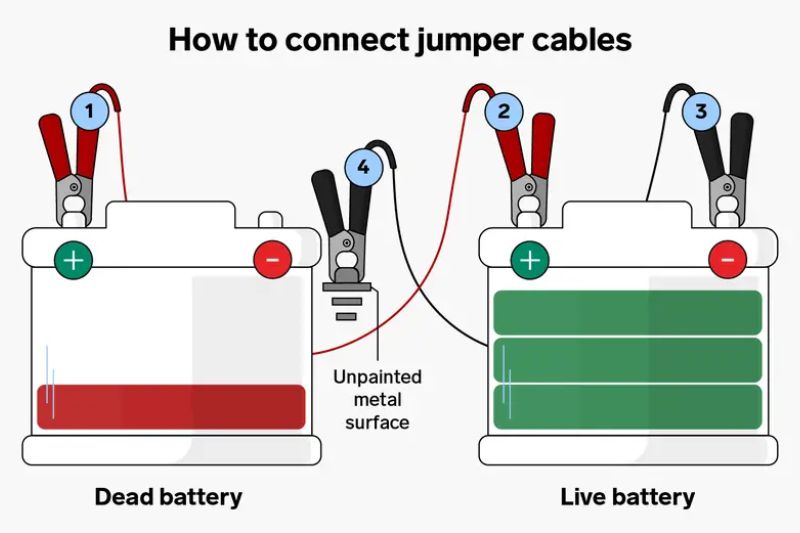
Battery disconnection is absolutely mandatory before working on starting system wiring. Always disconnect the negative terminal first, then the positive terminal. This sequence prevents accidental short circuits that could cause sparks, explosions, or damage to electronic components. Wait at least 15 minutes after disconnection to allow capacitors in electronic systems to discharge.
Modern vehicles often incorporate high-voltage systems, particularly in hybrid and electric vehicles. These systems can deliver lethal voltages even when the vehicle is turned off. Orange-colored wiring typically indicates high-voltage circuits that require specialized training and equipment to service safely. If you encounter orange wiring or high-voltage warning labels, stop immediately and consult a qualified technician.
Essential tools for safe electrical work include insulated hand tools rated for automotive voltages, a quality digital multimeter, and proper lighting to clearly see wire colors and connections. Never use damaged tools or work in poorly lit conditions. Additionally, ensure your work area is dry and free from flammable materials, as electrical work can create sparks.
The Four Critical Wire Categories for Car Starting
Battery Cables – The Power Supply Lines
Battery cables represent the foundation of your vehicle’s starting system, carrying the highest currents in the entire electrical system. The positive battery cable, typically 4 to 8 gauge wire, must handle currents exceeding 200 amperes during starting. This cable runs from the positive battery terminal to the starter motor’s main power terminal, often passing through junction boxes or directly to the starter solenoid.
The negative ground cable creates the return path for electrical current, connecting the negative battery terminal to the engine block and vehicle chassis. This connection is critical because the starter motor uses the engine block as its ground reference. A poor ground connection can prevent starting or cause the starter to operate inefficiently, drawing excessive current and generating heat.
Cable gauge requirements aren’t arbitrary—they’re determined by the current carrying capacity needed and the length of the wire run. Undersized cables create voltage drop, which reduces the voltage available to the starter motor and can prevent successful engine starting. Signs of inadequate or damaged battery cables include slow cranking, clicking sounds when attempting to start, or cables that feel warm after starting attempts.
Modern vehicles often incorporate additional safety features in battery cable design, including fusible links or mega-fuses that protect the entire electrical system from catastrophic short circuits. These protective devices are typically located near the battery or in the main fuse box and represent critical safety components that should never be bypassed.
Starter Motor Wiring Circuit
The starter motor circuit consists of two primary wire types: the main power wire and the control circuit wires. The main power wire, typically 8 to 10 gauge, carries the high current needed to operate the starter motor. This wire connects from the battery positive terminal (often through a main fuse or fusible link) to the starter solenoid’s main power terminal.
The starter solenoid control wire carries a much smaller current—typically 10 to 20 amperes—but serves the crucial function of energizing the solenoid coil. When energized, this solenoid closes heavy-duty contacts that allow battery power to flow to the starter motor. This control wire originates from the ignition switch start position and may pass through various safety interlocks.
Ground connections for the starter motor are equally important but often overlooked. The starter motor grounds through its mounting bolts to the engine block, which connects to the battery through the negative cable. Poor ground connections can cause starting problems that mimic more expensive component failures, making ground inspection a critical first step in starting system diagnosis.
Many modern vehicles incorporate starter relays that provide an additional layer of control and protection. These relays allow the ignition switch to control a small current while the relay handles the higher current needed to energize the starter solenoid. This design reduces wear on ignition switch contacts and provides more reliable operation.
Ignition Switch and Control Wiring
Ignition switch wiring serves as the command center for your vehicle’s starting system, translating your key turn or button press into electrical signals that activate various systems. The ignition switch power feed wire, typically connected to a constant 12-volt source through a fuse, provides power to the switch assembly itself.
The start signal wire carries the critical command from the ignition switch to the starter solenoid when you turn the key to the start position. This wire typically carries only 10 to 20 amperes but represents one of the most important connections in the starting system. A break in this wire will prevent starting entirely, even if all other components are functioning perfectly.
Modern vehicles integrate multiple safety interlocks into the starting circuit through the ignition switch wiring. These may include neutral safety switches in automatic transmissions, clutch position switches in manual transmissions, and brake pedal position switches in push-button start systems. Each of these safety devices is wired in series with the start signal, meaning any one can prevent starting if malfunctioning.
Anti-theft system integration has become increasingly complex in modern ignition switch wiring. Many vehicles now require communication between the ignition switch, body control module, and engine control module before starting is permitted. This integration means that starting problems can sometimes originate from seemingly unrelated systems, making proper diagnostic procedures essential.
Engine Control and Sensor Wiring
Engine control wiring has evolved dramatically with the introduction of computerized engine management systems. The engine control module (ECM) requires power, ground, and communication signals to authorize engine starting and provide proper fuel delivery and ignition timing. ECM power supply wiring failures can prevent starting even when the starter motor operates normally.
Crankshaft position sensor wiring provides critical information about engine rotation to the ECM. Without this signal, most modern engines will not start or will start and immediately stall. The crankshaft position sensor typically uses a three-wire configuration: power supply, ground, and signal, with each wire serving a specific function in the sensor circuit.
Camshaft position sensor connections work in conjunction with the crankshaft position sensor to provide precise timing information for fuel injection and ignition. Some engines can start without a camshaft position sensor signal, but performance will be severely degraded, and the engine may not start reliably under all conditions.
Fuel pump relay control wiring represents another critical component of modern starting systems. The ECM must energize the fuel pump relay to provide fuel pressure for engine starting. This circuit typically includes safety interlocks that shut off the fuel pump if the engine stops running, providing important safety protection in the event of an accident.
Step-by-Step Wire Identification Process
Locating the Main Battery Cables
Begin your wire identification process at the battery, where the largest and most obvious cables originate. The positive battery cable is typically red or has red markings, connecting to the larger terminal post marked with a “+” symbol. This cable will be one of the thickest in your vehicle, usually 4 to 8 gauge, reflecting its high current-carrying requirements.
Follow the positive cable from the battery to identify its routing through the engine bay. In most vehicles, this cable travels directly to the starter motor or to a main junction box that distributes power to multiple circuits. Pay attention to any fusible links or main fuses in this cable, as these provide critical overcurrent protection for your entire electrical system.
The negative battery cable, typically black, connects the negative battery terminal to the engine block and vehicle chassis. This cable may split into multiple paths: one connection to the engine block (often near the starter motor) and another to the vehicle chassis or body. Both connections are essential for proper system operation.
Junction box and fuse block connections often interrupt the direct path from battery to starter. Modern vehicles frequently route battery power through these distribution points to provide circuit protection and to supply power to other high-current systems. Understanding your vehicle’s specific routing is essential for effective troubleshooting.
Finding Starter Motor Connections
Locating the starter motor assembly requires familiarity with your specific vehicle’s engine layout. Starters are typically mounted on the transmission bell housing near where the engine and transmission meet. The starter motor will have at least two major electrical connections: a large terminal for main power and a smaller terminal for the solenoid control wire.
The main power terminal on the starter accepts the heaviest gauge wire in the starting system. This terminal is usually protected by a rubber or plastic boot to prevent accidental short circuits. Never remove this connection without first disconnecting the battery, as this terminal is always “hot” when the battery is connected.
Starter solenoid wiring connections vary by design but typically include a small terminal for the control wire from the ignition switch and may include additional terminals for other circuits. Some starters incorporate remote solenoids mounted separately from the starter motor, requiring additional wiring between the remote solenoid and starter motor.
Testing starter solenoid wiring requires careful attention to safety procedures. With the battery disconnected, you can check continuity between the ignition switch start terminal and the solenoid control terminal. With the battery connected but engine disabled (fuel pump fuse removed), you can test for voltage at the solenoid control terminal when attempting to start.
Ignition Switch Wiring Identification
Accessing ignition switch connections often requires removing steering column covers or dashboard panels. Before beginning this work, disconnect the battery and consult your vehicle’s service manual for specific procedures, as some vehicles incorporate airbag systems that can be dangerous if improperly handled.
Understanding wire color codes by manufacturer simplifies ignition switch identification. General Motors typically uses purple for start signal wires, while Ford often uses yellow or light green. However, these conventions aren’t universal, and proper identification requires consulting wiring diagrams specific to your vehicle’s year, make, and model.
Testing ignition switch continuity helps verify proper switch operation. Using a multimeter set to continuity mode, you can test whether the switch properly connects circuits in each key position. The start position should show continuity between the power feed and start signal terminals only when the key is held in the start position.
Modern push-button start systems incorporate significantly more complex wiring than traditional key switches. These systems typically involve communication between multiple modules and may require specialized diagnostic equipment to properly test. If you’re working on a push-button start system, consider consulting professional resources or seeking professional assistance.
Wire Gauge and Specifications for Starting Systems
Understanding Wire Gauge Requirements
Wire gauge selection for starting systems is driven by current carrying capacity and acceptable voltage drop. Heavier gauge wires (smaller gauge numbers) carry more current with less voltage drop, which is critical for high-current applications like starter motors. A 4-gauge cable can carry significantly more current than an 8-gauge cable with less voltage loss over the same distance.
Typical wire sizes for different circuits in starting systems follow established automotive standards. Main battery cables are usually 4 to 8 gauge, starter motor power wires are typically 8 to 10 gauge, and control circuits often use 12 to 16 gauge wire. Using undersized wire in any circuit can cause poor performance or complete system failure.
Voltage drop considerations become critical in high-current circuits. A voltage drop of just 0.5 volts in the main battery cable can reduce starter motor voltage from 12 volts to 11.5 volts, significantly impacting cranking performance. This is why proper wire gauge selection and maintaining clean, tight connections is essential for reliable starting.
Temperature effects also influence wire gauge requirements. Wires carrying high current generate heat, and hot wires have higher resistance than cold wires. Automotive wiring systems must be designed to handle worst-case conditions, including high ambient temperatures and sustained high-current operation during extended starting attempts.
Manufacturer-Specific Wiring Standards
General Motors vehicles typically follow consistent color coding conventions across their product lines. Red or red with tracer colors indicate positive power feeds, black indicates ground connections, and purple typically indicates start signal circuits. However, these conventions can vary between model years and specific vehicle lines.
Ford starting system wire colors have their own patterns, with yellow or light green often used for start signal circuits, red for power feeds, and black for grounds. Ford also frequently uses wire tracers (thin colored stripes) to differentiate between multiple wires of the same base color, requiring careful attention to wiring diagrams.
Import vehicle wiring differences can be significant, particularly in wire color coding and circuit protection methods. Japanese manufacturers often use different color conventions than domestic manufacturers, and European vehicles may incorporate different safety standards or circuit protection methods. Always consult manufacturer-specific wiring diagrams when working on import vehicles.
Universal aftermarket wiring standards exist for replacement components and custom installations. The Society of Automotive Engineers (SAE) has established standard color codes for aftermarket wiring, but these don’t always match original equipment manufacturer conventions. When installing aftermarket components, ensure compatibility with existing vehicle wiring.
Common Starting System Wiring Problems
Diagnosing Wire-Related Starting Issues
Symptoms of bad battery cables often mimic other starting system problems, making proper diagnosis essential. Slow cranking, clicking sounds, or complete failure to crank can all indicate battery cable problems. Cables that feel warm after starting attempts or show visible corrosion require immediate attention.
Signs of starter motor wiring problems include intermittent starting, starter motor operation without engine cranking, or unusual noises during starting attempts. A starter that operates but doesn’t engage the flywheel may indicate solenoid wiring problems rather than mechanical starter failure, highlighting the importance of electrical diagnosis before component replacement.
Ignition switch wiring failures often present as complete inability to start, with no response when turning the key to the start position. However, intermittent ignition switch problems can be more challenging to diagnose, particularly when they’re temperature or position sensitive. Testing ignition switch circuits under various conditions helps identify intermittent problems.
Intermittent connection issues represent some of the most challenging starting system problems to diagnose. These problems may be temperature sensitive, vibration sensitive, or dependent on specific environmental conditions. Thorough visual inspection and gentle manipulation of suspect connections often reveals loose or corroded connections that cause intermittent problems.
Testing and Troubleshooting Procedures
Using a multimeter to test continuity provides fundamental diagnostic information about starting system wiring. Set your meter to continuity or low resistance mode and test between known good connection points. A good wire should show near-zero resistance, while an open circuit will show infinite resistance or no continuity indication.
Voltage drop testing on power cables reveals problems that continuity testing might miss. With the starting system operating (engine disabled to prevent starting), measure voltage between the battery positive terminal and the starter motor power terminal. Voltage drop should not exceed 0.5 volts in a properly functioning circuit.
Load testing starter circuits goes beyond simple voltage measurements to test circuit performance under actual operating conditions. This testing requires specialized equipment that can safely load the circuit while measuring voltage and current. Load testing often reveals problems that aren’t apparent during no-load testing.
Checking ground connections requires testing both mechanical and electrical integrity. Loose ground connections can cause a variety of starting problems, from slow cranking to complete failure to start. Test ground connections by measuring resistance between the negative battery terminal and various ground points on the engine and chassis.
For comprehensive diagnostic procedures and detailed troubleshooting guides, consider consulting our diagnostic and troubleshooting resources for specific vehicle systems and components.
Tools and Equipment Needed for Starting System Work
Essential Diagnostic Tools
A quality digital multimeter represents the most important tool for starting system diagnosis. Choose a meter capable of measuring DC voltage up to at least 20 volts, resistance to 20 megohms, and current to at least 20 amperes. Auto-ranging meters simplify use and reduce the chance of selecting incorrect ranges during testing procedures.
Battery load tester requirements vary by application, but most automotive applications require testers capable of applying loads up to 200 amperes for 15 seconds. Professional-grade load testers include temperature compensation and can test both starting and deep-cycle batteries. Load testing reveals battery condition under actual operating conditions that simple voltage measurements cannot detect.
Wire strippers and crimping tools designed for automotive applications ensure proper connections when repairing or replacing starting system wiring. Automotive crimping tools create gas-tight connections that resist corrosion better than household electrical crimpers. Invest in quality tools designed specifically for automotive wire gauges and terminal types.
Circuit testers and test lights provide quick go/no-go testing for starting system circuits. However, modern vehicles with sensitive electronic systems require special precautions when using test lights. LED test lights draw less current than incandescent types and are safer for use on computer-controlled vehicles.
Safety Equipment and Materials
Insulated tools rated for automotive voltages protect against accidental short circuits and electrical shock. All hand tools used on starting systems should have insulated handles rated for at least 1000 volts, even though automotive systems operate at much lower voltages. This provides safety margin and protects against induced voltages in some circuits.
Replacement wire and terminal hardware should meet or exceed original equipment specifications. Use only automotive-grade wire with appropriate temperature and chemical resistance ratings. Marine-grade wire offers superior corrosion resistance but may not meet automotive temperature requirements in engine bay applications.
Electrical tape and heat shrink tubing provide essential protection for electrical connections. Heat shrink tubing with adhesive lining provides superior moisture protection compared to electrical tape alone. Use heat shrink tubing on all connections exposed to moisture or temperature extremes.
Battery terminal cleaning supplies include wire brushes, terminal cleaning solutions, and protective coatings. Clean battery terminals ensure reliable electrical connections and prevent corrosion-related starting problems. Regular terminal cleaning represents one of the most effective preventive maintenance procedures for starting systems.
When to Call a Professional Technician
Complex Modern Vehicle Systems
Hybrid and electric vehicle considerations require specialized training and equipment that exceed typical DIY capabilities. High-voltage systems in these vehicles can be lethal and require specific safety procedures and protective equipment. If your vehicle has orange high-voltage warning labels, consult qualified technicians with hybrid/electric vehicle training.
Advanced anti-theft system integration in modern vehicles often requires specialized diagnostic equipment and programming procedures. Some starting system problems originate from anti-theft system malfunctions that can only be diagnosed with manufacturer-specific scan tools and software. Attempting to bypass anti-theft systems can damage expensive electronic components.
Computer-controlled starting systems incorporate multiple interconnected modules that communicate through data networks. Diagnosis of these systems often requires bi-directional scan tool capabilities to command modules and monitor their responses. Network communication problems can prevent starting even when individual components test properly.
Warranty considerations for newer vehicles should influence your decision to attempt DIY repairs. Improper repair procedures can void vehicle warranties and potentially create safety hazards. For vehicles still under warranty, consult authorized service centers for starting system problems.
Signs You Need Professional Help
Multiple electrical system failures often indicate problems beyond individual component failures. Simultaneous failure of starting, charging, and accessory systems suggests problems with main power distribution that require systematic diagnosis and repair procedures beyond typical DIY capabilities.
Recurring starting problems after repairs indicate either inadequate initial diagnosis or more complex underlying problems. Professional technicians have access to diagnostic equipment and technical information that can identify root causes that might not be apparent during basic testing procedures.
If you’re unfamiliar with automotive electrical systems, starting system work can be dangerous and expensive if performed incorrectly. Electrical system mistakes can damage expensive electronic components or create safety hazards that far exceed the cost of professional service.
Lack of proper diagnostic equipment limits your ability to perform thorough starting system diagnosis. Professional shops invest in specialized equipment designed specifically for automotive electrical diagnosis that provides capabilities unavailable with basic multimeters and test lights.
For professional assistance with complex electrical problems, visit our contact page to connect with qualified technicians in your area.
Preventive Maintenance for Starting System Wiring
Regular Inspection Procedures
Visual inspection of battery cables should be performed monthly, looking for signs of corrosion, chafing, or loose connections. Green or white powdery deposits around battery terminals indicate corrosion that can increase resistance and cause starting problems. Address corrosion immediately to prevent damage to cables and terminals.
Cleaning battery terminals and connections represents one of the most effective preventive maintenance procedures for starting systems. Remove terminals, clean with a wire brush and baking soda solution, and apply protective coating to prevent future corrosion. Ensure terminals are tight but not overtightened, which can damage battery posts.
Checking for wire chafing and damage requires following wiring harnesses through their routing paths, paying particular attention to areas where wires contact sharp edges or moving components. Engine movement during operation can cause wires to rub against brackets or other components, eventually wearing through insulation and causing short circuits.
Testing connections under load reveals problems that might not be apparent during visual inspection. Connections that appear good visually may have high resistance under load due to corrosion or loose contact surfaces. Load testing should be performed annually or whenever starting problems are encountered.
Protecting Wiring from Environmental Damage
Preventing corrosion in electrical connections requires understanding the mechanisms that cause corrosion and implementing appropriate protection measures. Moisture and road salt create ideal conditions for electrical corrosion, particularly in areas where dissimilar metals are in contact. Use dielectric grease on all electrical connections exposed to moisture.
Securing loose wiring harnesses prevents chafing damage and protects wires from heat sources. Use appropriate clips and ties designed for automotive applications that won’t cut into wire insulation or create stress concentrations. Avoid zip ties in areas subject to vibration, as they can cut through wire insulation over time.
Heat protection for wires near exhaust components requires careful attention during maintenance and repair procedures. Exhaust components can reach temperatures exceeding 1000°F, which can quickly damage even high-temperature automotive wiring. Use appropriate heat shields and maintain proper clearances between wiring and exhaust components.
Moisture protection strategies include proper routing of wiring harnesses to avoid water collection areas and ensuring all connections are properly sealed. Water can enter electrical connections through capillary action in wire strands, traveling significant distances inside wire insulation. Use appropriate sealants and ensure proper drainage in electrical enclosures.
For detailed maintenance procedures specific to your vehicle, explore our comprehensive vehicle care tips section for preventive maintenance guidance.re.
Related Resources and Further Reading
Understanding starting system wiring is just one aspect of automotive electrical systems. For comprehensive information about related systems, explore our detailed guides on vehicle electrical and lighting systems to understand how starting circuits integrate with other electrical components.
When starting problems persist despite proper wiring, the issue may lie with the starter motor itself. Our guide on spotting a bad starter motor provides detailed information about starter motor diagnosis and replacement procedures.
Battery and charging system problems often masquerade as starting system issues. Learn about battery diagnosis and maintenance to ensure your starting system has adequate power for reliable operation.
For comprehensive diagnostic procedures when you encounter starting problems, consult our diagnostic and troubleshooting guides that provide systematic approaches to identifying and resolving automotive electrical issues.
Modern vehicles incorporate complex engine management systems that interact with starting circuits. Understanding engine control systems helps diagnose starting problems that originate from computer-controlled components.
Disclaimer: This information is provided for educational purposes only. Automotive electrical work involves risks including electrical shock, fire, and damage to expensive components. Always consult professional technicians for complex electrical problems or when working on hybrid/electric vehicles. Implement all safety procedures and use appropriate personal protective equipment when working on automotive electrical systems. The information provided here is for reference only—implement repairs at your own risk and responsibility, always prioritizing safety first.
Ready to tackle your automotive electrical challenges? Explore our comprehensive collection of automotive repair manuals for detailed, vehicle-specific wiring diagrams and repair procedures that complement the fundamental knowledge you’ve gained here.ay!