Quick Answer: Brake drums are cylindrical, bowl-shaped brake components that rotate with the wheel and provide the friction surface for drum brake systems. When brake shoes press outward against the inner surface of the drum, the resulting friction converts the vehicle’s kinetic energy into heat energy, slowing or stopping the wheel rotation. This enclosed design offers superior brake dust containment, consistent braking force in both directions, and excellent corrosion protection compared to disc brakes.

Why Brake Drums Are Critical for Vehicle Safety
Brake drums serve as the foundation of drum brake systems, providing the essential friction surface that enables vehicles to stop safely and reliably. Unlike disc brakes that clamp pads against an external rotor, brake drums create an enclosed braking environment where brake shoes press outward against the drum’s inner surface, generating the friction necessary to halt wheel rotation.
The drum brake’s enclosed design offers several critical safety advantages. The system provides consistent braking force whether the vehicle moves forward or backward, making it particularly valuable for parking brake applications where reliable holding power is essential. Drum brakes generate consistent braking force whether the vehicle travels forward or backward. This is because drum brakes generate the same braking force in either direction. This bidirectional effectiveness ensures dependable performance regardless of driving conditions.
Environmental protection represents another key safety benefit. The drum brake technology is completely enclosed within a housing system that offers protection to the mechanical mechanism and brake surfaces against corrosive elements such as rain and salts. This enclosed housing system protects internal components from moisture, road salt, and debris that could compromise braking performance, while also significantly reducing particulate emissions compared to open disc brake systems.
The self-energizing effect inherent in drum brake design amplifies braking force through the servo action of the leading shoe, providing powerful stopping capability with relatively low pedal input force. This mechanical advantage makes drum brakes particularly effective for rear brake applications and heavy-duty parking brake systems where maximum holding power is required.
Quick Facts About Brake Drums:
- Function: Rotating friction surface for enclosed drum brake systems
- Location: Rear axles on most passenger vehicles, all axles on some commercial vehicles
- Materials: Primarily cast iron, some aluminum with steel liners
- Service Life: 60,000-100,000 miles depending on driving conditions
- Failure Impact: Complete loss of braking on affected wheel, potential parking brake failure
Safety Note: Brake drums operate under extreme heat and stress conditions. Always have drum brake systems inspected by qualified technicians if you notice unusual noises, reduced braking performance, or brake pedal changes. Brake system work requires specialized knowledge of hydraulic systems and proper safety procedures.
Brake Drum Parts and Construction Explained
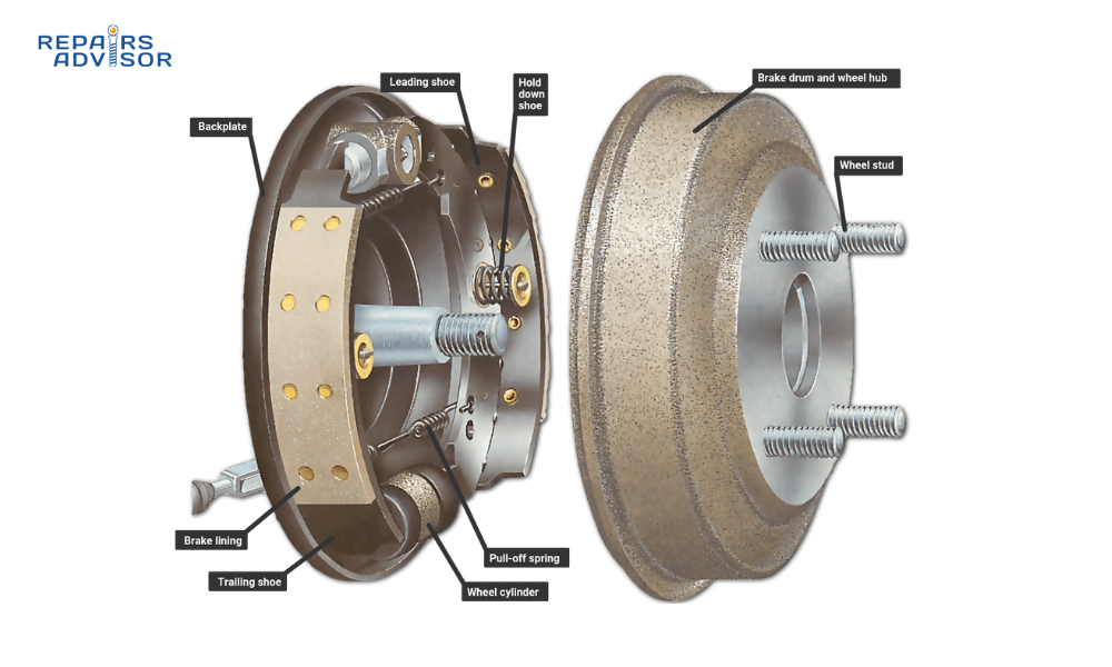
Brake drums feature robust construction designed to withstand the intense heat and mechanical stress of repeated braking cycles. The primary drum structure consists of a cylindrical bowl-shaped casting that mounts directly to the wheel hub or axle, rotating as an integral part of the wheel assembly.
The drum’s friction surface represents the most critical component – a precision-machined inner cylindrical surface against which the brake shoes make contact. The brake drum is generally made of a special type of cast iron that is heat-conductive and wear-resistant. It rotates with the wheel and axle. This friction surface must maintain precise dimensional tolerances and surface finish to ensure even brake shoe contact and optimal braking performance.
Cast iron remains the predominant material for brake drum construction due to its excellent thermal properties and durability. The material degree for brake drums is gray iron class 35 (HT250, FC250, GG25, ISO300, G250) with 1% copper (Cu). Their Brinell Hardness should be HB 180-250. The addition of copper enhances thermal conductivity and wear resistance, while the specified hardness range provides the optimal balance between durability and machinability.
Alternative construction methods include composite designs for weight reduction applications. To provide lightweight and sufficient strength, use CENTRIFUSE brake drums. These drums are made of steel with a cast-iron liner for the braking surface. This construction combines the strength and weight advantages of steel with the superior friction characteristics of cast iron, though at higher manufacturing cost.
Key structural components include the mounting flange or hub interface, which provides secure attachment to the wheel assembly, and the outer heat dissipation fins on some heavy-duty applications. The drum’s wall thickness varies strategically – thicker at the friction surface for heat absorption and thinner at the outer areas for weight optimization and thermal expansion management.
Material variations serve specific applications: aluminum drums with steel or iron liners offer weight reduction for performance applications, while specialty vermicular cast iron provides enhanced thermal fatigue resistance for severe-duty commercial applications. The selection depends on the vehicle’s weight, performance requirements, and operating environment.
How Brake Drums Work: Step-by-Step Operation
Brake drum operation involves a coordinated hydraulic and mechanical process that converts driver input into reliable stopping force. The system begins when the driver presses the brake pedal, initiating a chain of events that ultimately presses brake shoes against the drum’s inner surface through hydraulic pressure multiplication.
Step 1: Hydraulic Pressure Generation When the brake pedal is depressed, the master cylinder generates hydraulic pressure that travels through brake lines to the wheel cylinder mounted on the backing plate. Hydraulic pressure from the master cylinder acts on the piston cup, pushing the pistons toward the shoes, forcing them against the drum. This hydraulic system multiplies the driver’s foot force significantly, providing the mechanical advantage necessary for effective braking.
Step 2: Brake Shoe Actuation and Servo Effect The wheel cylinder’s pistons push the brake shoes outward against the drum’s inner surface, creating initial contact between the friction material and the rotating drum. The leading shoe is pressed in the same direction as the rotation of the drums, and this rotation helps to press the shoes against the drum with greater pressure for stronger braking force. This is called the servo effect (self-boosting effect) which realizes the powerful braking forces of drum brakes. This self-energizing action amplifies the applied force, making drum brakes exceptionally effective at generating high braking torque.
Step 3: Friction Energy Conversion As the brake shoes press against the rotating drum, kinetic energy converts to thermal energy through friction. This friction converts kinetic energy into thermal energy. Drum rotation helps to press the shoes and the lining against the drum with more force, offering superior braking force in comparison with disc brakes. The cast iron drum material efficiently absorbs and dissipates this heat energy, while the enclosed design contains wear particles and protects components from environmental contamination.
Step 4: Return and Reset Cycle When the driver releases the brake pedal, hydraulic pressure decreases and return springs pull the brake shoes away from the drum surface. When the driver releases the brakes, the brake shoe springs restore the shoes to their original (disengaged) position. This positive spring return ensures complete brake release and prevents drag that could cause premature wear or overheating.
The drum’s enclosed design creates several operational advantages: it captures most brake dust within the assembly, provides protection from environmental contamination, and maintains consistent performance in wet conditions. The system automatically adjusts for brake shoe wear through self-adjusting mechanisms that maintain proper shoe-to-drum clearance as components wear during normal operation.
Modern drum brake systems integrate with vehicle stability systems, providing brake-by-wire capabilities and enhanced electronic control for applications like hill-hold assist and stability management. The drum’s thermal mass and enclosed design make it particularly well-suited for electric and hybrid vehicles where regenerative braking reduces thermal cycling frequency.
Brake Drum Location and Access Guide
Brake drums are typically located on the rear wheels of most passenger vehicles, though some commercial vehicles and older cars use drum brakes on all four wheels. The drum assembly mounts directly behind the wheel, integrated with the hub assembly or axle flange, making it visible once the wheel is removed.
Visual Identification and Characteristics A brake drum appears as a deep, cylindrical metal bowl approximately 8-12 inches in diameter for passenger cars, with a smooth, machined inner surface and often a finned or ribbed outer surface for heat dissipation. Their weights are usually from 10kg to 45kg. They are widely used for the many kinds of vehicles such as cars, trucks, tractors etc The drum’s substantial weight and robust construction make it easily distinguishable from other wheel components.
The drum typically shows a part number and specifications cast or stamped into the outer surface, along with maximum diameter specifications that indicate wear limits. Visible mounting points include bolt holes or studs that secure the drum to the hub assembly, and the smooth, precise finish of the inner braking surface can be observed by looking through the access holes in the backing plate.
Access Requirements and Safety Considerations Accessing brake drums requires standard tire removal procedures plus specific drum brake tools and safety equipment. Essential tools include a jack and jack stands rated for the vehicle weight, tire iron or impact gun for wheel removal, and often a drum puller for drums that resist removal due to wear ridges or self-adjusting mechanism tension.
Safety Warning: Brake drums operate under extreme heat and contain asbestos-like friction materials in older vehicles. Always wear appropriate respiratory protection when servicing drum brakes, ensure the vehicle is properly supported on jack stands, and never work under a vehicle supported only by a jack. The heavy weight of brake drums (10-45 kg) requires proper lifting techniques to prevent injury.
Vehicle-specific access variations depend on the suspension and axle design. Front-wheel-drive vehicles typically have simpler rear drum access, while rear-wheel-drive vehicles may require additional clearance around the differential. Some drums are integral with the hub bearing assembly, requiring special tools and procedures for removal, while others slide off once retaining hardware is removed.
Professional service becomes necessary when drums require machining to remove wear ridges, when wheel cylinders need replacement, or when brake shoes require adjustment beyond the self-adjusting mechanism’s range. In severe cases the ridge can make the brake drum captive, however most drum brake designs provide a way to externally release the self-adjusting mechanism in order to ease drum removal and service. Understanding these release mechanisms prevents damage during service procedures.
For DIY inspection, brake drums can be visually checked for external cracks, excessive scoring, or heat discoloration after wheel removal. However, internal inspection for wear limits, cracking, or out-of-round conditions requires drum removal and specialized measuring equipment. Always consult vehicle-specific service manuals for proper procedures, torque specifications, and safety precautions before attempting drum brake service.
Related Articles and Resources
Direct Component Articles:
- How ABS Systems Work – Understanding how drum brakes integrate with anti-lock braking systems
- How Master Cylinders Work – The hydraulic control center that operates drum brake systems
- How Brake Fluid Works – Essential hydraulic medium for drum brake operation
Related System Articles:
- How Your Car’s Suspension Works – Understanding how braking forces interact with suspension components
- How Disc Brakes Work – Comparing disc and drum brake technologies and applications
Troubleshooting and Support:
- Have Not Received My Order – Assistance with manual downloads and delivery issues
- Download & Open Issues – Help with accessing brake system repair manuals
Brand-Specific Information:
- FORD Manuals – Ford-specific brake drum service procedures and specifications
- TOYOTA Manuals – Toyota brake system documentation and repair guides
- Trucks Category – Commercial vehicle brake systems and heavy-duty applications
