⚠️ Safety Notice: Working with vehicle electrical systems requires proper safety precautions. Always disconnect the battery before performing electrical work. This information is for educational purposes only. Consult professional technicians for safety-critical repairs.
The clutch safety switch stands as one of the most critical yet often overlooked safety components in manual transmission vehicles. This small but essential device prevents your engine from starting unless the clutch pedal is fully depressed, protecting both you and your vehicle from potentially dangerous situations. Understanding how this safety mechanism works, recognizing when it fails, and knowing how to address problems can save you from costly repairs and ensure your vehicle operates safely.
Whether you’re a DIY enthusiast working on your own vehicle or a professional mechanic diagnosing customer complaints, mastering clutch safety switch operation and repair is fundamental to manual transmission system expertise. This comprehensive guide covers everything from basic function to advanced diagnostic procedures, helping you confidently handle any clutch safety switch issue.
What Is a Clutch Safety Switch and Why Is It Critical?
Basic Function and Safety Purpose
The clutch safety switch serves as a critical safety interlock that prevents engine starting when the transmission is in gear without the clutch being disengaged. This seemingly simple function prevents numerous potential accidents and mechanical damage scenarios that could occur if a vehicle started while in gear.
When you press the clutch pedal, the switch closes an electrical circuit that allows current to flow to the starter solenoid. Without this signal, the starter motor cannot engage, effectively preventing the engine from starting. This safety mechanism ensures that the transmission is always disconnected from the engine during startup, eliminating the risk of sudden vehicle movement.
The importance of this safety feature cannot be overstated. Without a functioning clutch safety switch, a vehicle could lurch forward or backward during startup if left in gear, potentially causing property damage, injury, or death. This is particularly critical in situations where the driver may forget the transmission position or when someone unfamiliar with the vehicle attempts to start it.
Alternative Names and Terminology
Understanding the various names for this component helps when searching for parts or consulting technical documentation. The clutch safety switch is commonly referred to by several alternative names throughout the automotive industry.
The clutch start cancel switch name reflects its function of canceling the normal starting sequence unless specific conditions are met. Some manufacturers prefer clutch interlock switch, emphasizing its role as an interlock device within the starting system. You may also encounter the term starter safety switch when specifically referring to manual transmission applications, distinguishing it from similar safety switches in automatic transmissions.
These naming variations are important to recognize because parts catalogs, service manuals, and diagnostic procedures may use different terminology depending on the manufacturer or publication. When ordering replacement parts or consulting vehicle-specific repair manuals, always verify you’re getting the correct component regardless of the name used.
Legal Requirements and Safety Standards
Federal Motor Vehicle Safety Standards (FMVSS) mandate specific safety requirements for vehicle starting systems, including clutch safety switch functionality. These regulations ensure consistent safety performance across all manual transmission vehicles sold in the United States.
Manufacturers must comply with these standards during vehicle production, but modifications or repairs that bypass or disable the clutch safety switch can create legal liability issues. Understanding these requirements helps ensure that any repair work maintains the vehicle’s original safety design and compliance status.
Professional technicians and serious DIY enthusiasts should always maintain these safety systems in their original configuration. While emergency bypasses may be necessary in certain situations, permanent modifications that disable safety switches should be avoided to maintain both legal compliance and operational safety.
How the Clutch Safety Switch Works
Electrical Circuit Operation
The clutch safety switch operates within a relatively simple electrical circuit, but understanding its precise function requires knowledge of both normally open and normally closed switch configurations. Most clutch safety switches use a normally open design, meaning the electrical contacts remain separated when the clutch pedal is released.
When you depress the clutch pedal, the switch mechanism closes, completing the electrical circuit between the ignition switch and the starter solenoid. This allows battery voltage to reach the starter motor, enabling engine cranking. The switch must remain closed throughout the entire starting sequence, ensuring the clutch stays disengaged during startup.
The electrical load on the clutch safety switch is typically minimal, as it controls a signal circuit rather than the full starter motor current. This low-current design contributes to switch longevity but also makes the circuit susceptible to corrosion and poor connections that can cause intermittent operation.
Integration with the vehicle’s ignition system varies by manufacturer, but the basic principle remains consistent across all applications. Some modern vehicles incorporate the clutch safety switch signal into the engine control unit (ECU) for additional monitoring and diagnostic capabilities.
Mechanical Operation Process
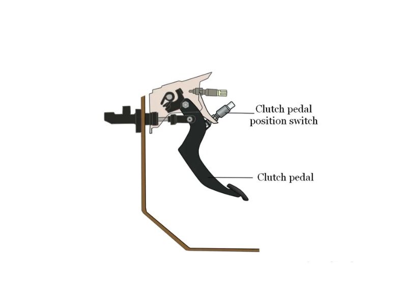
The mechanical operation of a clutch safety switch involves precise positioning and timing to ensure reliable function throughout the clutch pedal’s travel range. Most switches mount near the top of the clutch pedal travel, activating when the pedal reaches approximately 80-90% of its full depression.
This activation point ensures that the clutch is fully disengaged before the starter can operate, providing a safety margin that accounts for clutch wear and adjustment variations. The switch mechanism typically uses a spring-loaded plunger or lever that contacts the clutch pedal or a bracket attached to the clutch pedal assembly.
Proper adjustment is critical for reliable operation. If the switch activates too early in the pedal travel, the clutch may not be fully disengaged, potentially causing starter motor damage or transmission wear. If activation occurs too late, normal driving conditions might accidentally trigger the switch, causing unexpected starter engagement.
Understanding this mechanical relationship helps diagnose problems and ensures proper adjustment during installation or service. The clutch system’s overall operation directly affects switch performance, making comprehensive system knowledge essential for effective troubleshooting.
System Integration with Other Components
Modern vehicles integrate the clutch safety switch with various other systems to enhance overall vehicle safety and functionality. The relationship with the brake light switch creates redundant safety systems, as many vehicles require both clutch disengagement and brake application for certain functions like cruise control disengagement.
Anti-theft systems often monitor clutch safety switch signals as part of their security algorithms. Unexpected switch activation patterns can trigger security alerts or prevent engine starting, adding another layer of protection against vehicle theft. This integration requires careful consideration during diagnostic procedures, as problems in one system can affect others.
Some vehicles use the clutch safety switch signal for transmission control functions, particularly in automated manual transmissions or vehicles with electronic clutch assistance. These applications place additional demands on switch reliability and may require more sophisticated diagnostic approaches when problems occur.
Understanding these system interactions helps prevent misdiagnosis and ensures that repairs address all affected components. Complex integration means that what appears to be a simple switch problem may actually involve multiple vehicle systems requiring comprehensive diagnostic approaches.
Types of Clutch Safety Switches
Mechanical Push-Button Switches
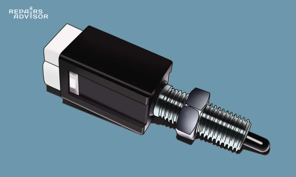
Traditional mechanical push-button switches represent the most common type of clutch safety switch found in older and many current vehicles. These switches use physical contact between mechanical components to open and close electrical circuits, providing reliable operation with minimal complexity.
The typical mechanical switch consists of a housing containing spring-loaded contacts, an actuator button or plunger, and electrical terminals for circuit connection. When the clutch pedal depresses the actuator, internal contacts close, completing the starter circuit. Release of the clutch pedal allows the spring to return the actuator to its rest position, opening the contacts.
Mounting locations vary, but most mechanical switches attach to the clutch pedal bracket or firewall near the pedal pivot point. This positioning allows the pedal or an attached actuator arm to operate the switch throughout the normal range of clutch pedal travel.
These switches offer excellent durability and field serviceability, with many lasting the entire vehicle lifetime under normal operating conditions. However, they are susceptible to contamination, corrosion, and mechanical wear that can cause intermittent operation or complete failure.
Magnetic Proximity Switches
Modern vehicles increasingly use magnetic proximity switches that detect clutch pedal position without physical contact between moving parts. These switches use magnetic field changes to determine pedal position, eliminating mechanical wear and improving reliability in harsh operating environments.
A typical magnetic proximity switch consists of a sensor unit containing a magnetic field generator and detector, plus a magnet or magnetic target attached to the clutch pedal assembly. As the pedal moves, the changing magnetic field triggers the switch to change states, providing the same electrical function as a mechanical switch.
The contactless operation offers significant advantages in terms of longevity and resistance to contamination. Without physical contacts to wear or corrode, magnetic switches can provide consistent operation throughout extended service intervals. They also offer more precise switching points and can provide variable output signals for advanced diagnostic purposes.
However, magnetic switches require more complex circuitry and are generally more expensive than mechanical alternatives. They may also be sensitive to electromagnetic interference or external magnetic fields that can cause false triggering or operation problems.
Integrated Clutch Position Sensors
The most advanced clutch safety switch designs integrate multiple functions into a single sensor unit that monitors clutch pedal position continuously rather than simply detecting on/off states. These sensors provide detailed position information to the vehicle’s control systems for enhanced functionality and diagnostics.
Integrated sensors typically use potentiometric or digital encoding methods to provide precise position feedback throughout the entire clutch pedal travel range. This information enables advanced features like electronic clutch assistance, automatic rev-matching, and sophisticated anti-theft functions.
The continuous monitoring capability allows vehicle control systems to detect gradual changes in clutch system operation that might indicate wear or adjustment needs. This predictive capability can alert drivers to maintenance requirements before complete system failure occurs.
These advanced sensors require sophisticated control system integration and typically cannot be retrofitted to older vehicles. They represent the current direction of automotive technology but also introduce complexity that requires specialized diagnostic equipment and training for effective service.
Common Clutch Safety Switch Problems and Symptoms
Primary Failure Symptoms
Recognizing the early warning signs of clutch safety switch problems can prevent being stranded and help avoid more serious complications. The most obvious symptom is an engine that refuses to start even with the clutch pedal fully depressed, but several other symptoms can indicate developing problems before complete failure occurs.
Intermittent starting problems often represent the early stages of switch failure. You might notice that the engine starts normally most of the time but occasionally requires multiple attempts or specific clutch pedal positioning to achieve starter engagement. These intermittent issues typically worsen over time as the underlying problem progresses.
Another concerning symptom is starter engagement without clutch pedal depression. This represents a serious safety hazard and indicates that the switch has failed in the closed position or that the circuit has been bypassed. Immediate attention is required when this symptom appears, as it eliminates the safety protection the switch is designed to provide.
Some drivers report that they must press the clutch pedal beyond the normal engagement point to achieve starter operation. This symptom often indicates switch misalignment or adjustment problems rather than complete switch failure, making it a good candidate for adjustment correction rather than replacement.
Understanding these symptoms and their progression helps prioritize repair urgency and guides diagnostic approaches. For comprehensive clutch system evaluation, consider reviewing our detailed guide on signs of a bad clutch safety switch for additional symptom recognition information.
Electrical Problems
Open Circuit Conditions
Open circuit conditions represent one of the most common electrical failures in clutch safety switch systems. These problems prevent current flow through the switch circuit, effectively disabling the starter system regardless of clutch pedal position.
Complete switch failure typically results from internal contact damage, where the electrical contacts no longer make reliable connection when the switch activates. This can occur due to arcing damage from high current loads, corrosion buildup, or mechanical wear that prevents proper contact alignment.
Wiring harness damage represents another common source of open circuit conditions. The wires connecting the clutch safety switch to the vehicle’s electrical system experience constant flexing as the clutch pedal operates, making them susceptible to fatigue failure. Additionally, routing near hot exhaust components or sharp metal edges can cause insulation breakdown and conductor damage.
Connector corrosion frequently causes intermittent open circuit conditions that worsen over time. Moisture intrusion into electrical connectors promotes corrosion that increases electrical resistance and eventually prevents current flow. This problem is particularly common in vehicles operated in harsh environments or those with damaged connector seals.
Short Circuit Issues
Short circuit conditions in clutch safety switch systems create safety hazards by bypassing the intended safety function. These problems can allow starter operation without clutch engagement, potentially causing vehicle movement during startup attempts.
Internal switch damage can create unintended electrical paths that maintain circuit continuity regardless of switch position. This typically results from physical damage to the switch housing or internal components that allows electrical contact in all positions.
Water intrusion represents a serious threat to clutch safety switch integrity, as moisture can create conductive paths that bypass the normal switching function. This is particularly problematic in vehicles exposed to flooding or those with damaged environmental seals around the switch mounting area.
Some technicians or vehicle owners attempt to bypass clutch safety switches to address starting problems without proper diagnosis. While this may temporarily restore starting capability, it eliminates critical safety protection and should only be considered as an emergency measure with immediate proper repair planned.
Mechanical Problems
Switch Misalignment
Proper clutch safety switch alignment is critical for reliable operation throughout the clutch pedal’s travel range. Misalignment can cause premature or delayed switch activation, leading to starting problems or safety concerns.
Improper adjustment symptoms include hard starting that requires excessive clutch pedal travel or starter engagement that occurs before the clutch is fully disengaged. These problems often develop gradually as clutch components wear or mounting hardware loosens over time.
Mounting bracket issues can cause switch misalignment even when the switch itself is functioning properly. Bent brackets, loose mounting hardware, or worn pivot points can change the relationship between the clutch pedal and switch activation point.
Clutch pedal wear affects switch operation by changing the pedal’s travel characteristics and the forces applied to the switch actuator. Worn pedal bushings or pivot points can introduce play that affects switch timing and reliability.
Physical Damage
Physical damage to clutch safety switches can result from various causes, ranging from accident damage to normal wear from repetitive operation. Understanding these damage modes helps identify repair requirements and prevention strategies.
Impact damage from accidents can affect switch mounting, wiring, or the switch mechanism itself. Even minor collisions that don’t appear to affect the clutch pedal area can cause misalignment or internal damage that affects switch operation.
Repetitive use wear is inevitable in high-mileage vehicles, particularly those used in commercial applications or stop-and-go driving conditions. The constant cycling of the switch mechanism eventually causes wear that can lead to intermittent operation or complete failure.
Environmental deterioration affects switches exposed to moisture, road salt, or extreme temperatures. Corrosion of switch housings, mounting hardware, or electrical connections can compromise both mechanical and electrical function over time.
Diagnostic Procedures for Clutch Safety Switch Testing
Visual Inspection Methods
Effective clutch safety switch diagnosis begins with thorough visual inspection that can identify many common problems without requiring test equipment. A systematic approach to visual inspection saves time and helps focus additional testing on the most likely problem areas.
Switch mounting verification involves checking that the switch is properly positioned relative to the clutch pedal and that all mounting hardware is tight and undamaged. Look for signs of impact damage, corrosion, or modification that might affect switch operation.
Wiring harness examination should include checking for damaged insulation, broken conductors, or signs of overheating near the switch connections. Pay particular attention to areas where the harness might contact moving parts or sharp edges that could cause damage over time.
Connector condition assessment involves inspecting electrical connectors for corrosion, damage, or loose connections. Many intermittent problems result from poor electrical connections rather than switch failure, making this inspection step particularly valuable.
The visual inspection should also include checking the clutch pedal operation for proper travel, smooth movement, and correct return to the rest position. Problems with the clutch pedal mechanism can affect switch operation even when the switch itself is functioning properly.
Electrical Testing Procedures
Continuity Testing
Continuity testing provides definitive information about switch electrical function and helps distinguish between switch problems and circuit issues. Proper testing requires understanding the switch’s electrical configuration and the correct test procedures for each type.
Multimeter setup for continuity testing requires selecting the appropriate test function and understanding the expected readings for both switch positions. Most digital multimeters include an audible continuity function that simplifies testing by providing audio feedback when continuity exists.
Switch position testing involves operating the clutch pedal while monitoring continuity across the switch terminals. The reading should change definitively between open and closed positions, with consistent operation through multiple test cycles.
Circuit integrity verification extends testing beyond the switch itself to include the complete electrical path from the ignition switch to the starter solenoid. This comprehensive testing helps identify wiring problems that might be confused with switch failure.
⚠️ Important: Always disconnect the battery before performing electrical testing to prevent accidental starter engagement and potential injury.
Voltage Testing
Voltage testing provides information about power supply adequacy and signal quality that continuity testing cannot reveal. This testing is particularly important for diagnosing intermittent problems or issues related to electrical system loading.
Power supply verification involves checking that proper voltage reaches the switch when the ignition is in the start position. Low voltage or voltage drops under load can cause intermittent starting problems that might be mistakenly attributed to switch failure.
Signal output measurement requires testing the voltage present at the switch output when the switch is activated. This test verifies that the switch can properly control voltage to the starter circuit under actual operating conditions.
Load testing procedures involve checking switch operation while the starter circuit is active, simulating real-world operating conditions. Some switches may pass basic continuity tests but fail under the electrical loads present during actual starting attempts.
Advanced Diagnostic Techniques
Scan Tool Analysis
Modern vehicles often integrate clutch safety switch monitoring into their diagnostic systems, providing additional troubleshooting capabilities through scan tool analysis. This electronic monitoring can reveal problems that traditional testing methods might miss.
Error code interpretation requires understanding how different vehicle manufacturers implement clutch safety switch monitoring and what specific codes indicate. Not all vehicles generate codes for clutch safety switch problems, but those that do provide valuable diagnostic information.
Live data monitoring allows real-time observation of clutch safety switch signals as interpreted by the vehicle’s control systems. This capability can help identify timing issues, signal quality problems, or intermittent failures that occur during actual operation.
System functional tests available through scan tools can command various system operations to verify proper integration between the clutch safety switch and other vehicle systems. These tests help identify problems that affect system interaction rather than basic switch function.
Oscilloscope Testing
Oscilloscope testing provides the most detailed analysis of clutch safety switch electrical behavior, revealing signal quality issues and timing problems that other test methods cannot detect. This advanced testing is particularly valuable for diagnosing intermittent problems or issues in complex integrated systems.
Signal waveform analysis shows the actual electrical behavior of the switch during operation, including rise and fall times, signal stability, and any electrical noise or interference. These details help identify problems with switch quality or circuit integrity.
Switch response timing measurement can reveal problems with mechanical operation that affect electrical performance. Slow switch activation or delayed signal changes might indicate mechanical wear or lubrication problems within the switch mechanism.
Electrical noise detection capabilities help identify interference sources that might affect switch operation in vehicles with complex electrical systems. This analysis is particularly important in vehicles with extensive electronic systems that might generate electromagnetic interference.
Clutch Safety Switch Replacement Guide
Pre-Replacement Preparation
Safety Precautions
Proper safety preparation is essential before beginning any clutch safety switch replacement procedure. The electrical nature of this repair and its location near moving parts require specific safety measures to prevent injury and equipment damage.
Battery disconnection procedures must be followed precisely to prevent accidental starter engagement during the repair process. Always disconnect the negative battery terminal first and secure it away from the battery post to prevent accidental reconnection. Wait at least 10 minutes after disconnection to allow any stored electrical energy to dissipate.
Personal protective equipment should include safety glasses to protect from debris, work gloves to prevent cuts from sharp edges, and appropriate clothing that won’t catch on moving parts. The confined workspace around the clutch pedal area requires particular attention to personal safety.
Work area safety setup involves ensuring adequate lighting and access to the clutch pedal area. Use appropriate jacks and jack stands if working under the vehicle, and never rely solely on hydraulic jacks for support. Ensure the vehicle is on level ground with the parking brake applied and transmission in neutral.
Tool Requirements
Successful clutch safety switch replacement requires having the correct tools available before beginning work. Missing tools can lead to improper installation or damage to surrounding components.
Basic hand tools needed typically include various sizes of screwdrivers, wrenches, and pliers for removing mounting hardware and electrical connections. The specific sizes required vary by vehicle, so consult the appropriate service manual for your specific application.
Specialized diagnostic equipment may be necessary for vehicles with integrated electronic systems that require recalibration after switch replacement. Some modern vehicles need scan tool access to complete the installation process properly.
Replacement part verification involves confirming that the new switch matches the original part’s specifications and mounting configuration. Using an incorrect switch can result in improper operation or safety hazards, so always verify part numbers against the vehicle’s specifications.
Removal Procedures
Electrical Disconnection
Proper electrical disconnection prevents damage to both the switch and the vehicle’s electrical system during removal. The specific procedures vary depending on the connector type and accessibility in each vehicle.
Proper connector removal requires understanding the specific connector design used in your vehicle. Some connectors use locking tabs that must be depressed before the connector will separate, while others use twist-lock or push-pull designs. Force should never be necessary to disconnect properly functioning connectors.
Wire routing documentation helps ensure correct reinstallation by recording the original wire routing and any securing clips or brackets. Take photos of the original installation before disconnection to aid in proper reassembly.
Anti-static precautions become important when working with electronic switches or vehicles with sensitive control systems. Use proper grounding techniques and avoid touching electronic components unnecessarily to prevent static damage.
Physical Switch Removal
Physical switch removal requires careful attention to mounting hardware and access procedures that vary significantly between vehicle models. Some switches are easily accessible, while others require removal of panels or other components for access.
Mounting hardware removal should be done systematically, keeping track of washers, spacers, and adjustment hardware that must be reinstalled correctly. Some switches use specialized mounting brackets that require specific removal sequences.
Access panel procedures may be necessary in vehicles where the switch is located behind dashboard panels or other interior components. Follow proper panel removal procedures to prevent damage to clips, fasteners, or surrounding components.
Component extraction techniques depend on the specific switch design and mounting method. Some switches require specific orientations or sequences for removal without damage to the switch housing or mounting points.
Installation Process
New Switch Installation
Proper installation of the new clutch safety switch ensures reliable operation and maintains the vehicle’s safety systems. Attention to mounting position, adjustment, and electrical connections is critical for successful installation.
Proper positioning methods involve aligning the new switch exactly as the original was mounted, using any reference marks or measurements taken during removal. Incorrect positioning can result in improper activation timing or switch damage.
Mounting torque specifications must be followed to prevent damage to the switch housing or mounting points while ensuring secure installation. Over-tightening can crack plastic switch housings, while under-tightening can allow movement that affects operation.
Adjustment procedures vary by vehicle but typically involve setting the switch activation point relative to clutch pedal travel. This adjustment is critical for proper safety function and may require specific measurement tools or procedures outlined in the service manual.
Electrical Reconnection
Electrical reconnection must recreate the original circuit configuration to ensure proper system integration and function. Incorrect connections can cause system malfunction or safety hazards.
Connector installation should result in secure, weather-tight connections that won’t vibrate loose during normal vehicle operation. Ensure that connector locks engage properly and that no wires are pinched or stressed by the installation.
Wire routing verification involves following the original routing path and securing the wiring harness to prevent contact with moving parts or heat sources. Proper routing prevents premature wire failure and maintains the professional appearance of the installation.
System integration testing involves checking that the new switch operates correctly within the vehicle’s complete electrical system. This may require scan tool access or specific test procedures depending on the vehicle’s complexity.
Adjustment and Calibration Procedures
Manual Adjustment Methods
Proper clutch safety switch adjustment ensures optimal performance throughout the clutch system’s service life. Manual adjustment procedures vary by vehicle but follow common principles that apply across most applications.
Switch position optimization involves setting the activation point to occur when the clutch is fully disengaged but before the pedal reaches its mechanical travel limit. This provides proper safety function while maintaining reasonable pedal feel for the driver.
Clutch pedal travel verification requires measuring the actual pedal movement to ensure the switch activates within the correct range. Most manufacturers specify activation within the last 10-20% of pedal travel, but specific requirements vary by application.
Engagement point setting may require coordination with clutch system adjustment, particularly in vehicles with cable-operated clutches or those with significant wear. The switch adjustment and clutch adjustment must work together to provide proper system function.
For vehicles requiring complex clutch system work, consider consulting our comprehensive guide on drivetrain systems for additional system integration information.
Electronic Calibration
Modern vehicles with electronic clutch safety switch integration may require specific calibration procedures after switch replacement or adjustment. These procedures ensure that the vehicle’s control systems recognize and properly interpret the new switch signals.
ECU learning procedures allow the engine control unit to adapt to the new switch’s specific electrical characteristics and timing. Some vehicles perform this learning automatically during normal operation, while others require specific procedures to initiate the learning process.
Adaptive adjustment systems in some vehicles continuously monitor clutch safety switch operation and adjust their response parameters based on observed behavior. These systems typically require several drive cycles to complete their adaptation after switch replacement.
Diagnostic validation involves using scan tool capabilities to verify that the control system properly recognizes switch operation and that all related systems integrate correctly with the new switch installation.
Troubleshooting Common Issues
Intermittent Starting Problems
Intermittent starting problems represent one of the most challenging diagnostic scenarios for clutch safety switch issues. These problems often stem from marginal electrical connections or mechanical wear that causes occasional operation failures.
Systematic diagnosis approach involves documenting when the problem occurs, what conditions seem to trigger it, and what actions restore normal operation. This information helps focus diagnostic efforts on the most likely causes.
Environmental factor consideration includes temperature effects, moisture conditions, and vibration that might affect switch operation. Some problems only occur under specific environmental conditions, making this analysis crucial for effective diagnosis.
Electrical connection verification should focus on connections that might be affected by temperature changes, vibration, or moisture. Cleaning and tightening connections often resolves intermittent problems without requiring switch replacement.
False Positive Triggers
False positive triggers occur when the clutch safety switch activates unexpectedly, potentially causing starter engagement at inappropriate times. These problems represent serious safety hazards requiring immediate attention.
Switch oversensitivity causes can include incorrect adjustment, worn mounting hardware, or internal switch problems that cause activation with minimal pedal movement. Identifying the root cause guides the appropriate correction strategy.
Adjustment correction methods involve readjusting the switch position to require more definitive clutch pedal travel before activation. This must be balanced against ensuring reliable activation when needed for starting.
System parameter modification may be possible in vehicles with electronic clutch safety switch integration, allowing adjustment of the activation threshold or timing through scan tool programming.
Complete System Failure
Complete system failure requires immediate attention but may also require temporary measures to maintain vehicle mobility while proper repairs are arranged.
Emergency bypass procedures should only be used temporarily and with full understanding of the safety implications. Any bypass eliminates the safety protection the switch provides and should be reversed as soon as proper repair is possible.
⚠️ Important: Clutch safety switches are critical safety components. Improper installation or bypass can result in serious accidents. Follow manufacturer specifications and local safety regulations.
Safety considerations for temporary solutions include ensuring that all operators understand the modified starting procedure and the increased risk of accidental vehicle movement during startup. Consider using additional safety measures like always applying the parking brake before starting.
Professional consultation requirements become important when dealing with complex electronic systems or safety-critical repairs. Some repairs require specialized equipment or expertise that make professional service the safer choice.
Prevention and Maintenance
Regular Inspection Schedule
Preventive maintenance of clutch safety switch systems helps avoid unexpected failures and ensures continued safe operation. Regular inspection can identify developing problems before they cause complete system failure.
Recommended inspection intervals should align with regular vehicle maintenance schedules, typically during oil changes or other routine service. Visual inspection of the switch, wiring, and mounting can be performed quickly during these service intervals.
Warning sign recognition helps vehicle owners and technicians identify problems before complete failure occurs. Early intervention often allows adjustment or minor repair rather than complete replacement.
Proactive replacement timing considers both mileage and operating conditions to replace switches before failure occurs. Vehicles used in severe service conditions may require more frequent replacement than those used primarily for highway driving.
Environmental Protection
Environmental factors significantly affect clutch safety switch longevity, making protection measures important for vehicles operated in harsh conditions.
Moisture prevention methods include ensuring proper sealing of electrical connections and checking that drainage paths around the clutch pedal area function correctly. Water intrusion is one of the most common causes of premature switch failure.
Corrosion protection strategies involve using appropriate electrical contact protectors and ensuring that mounting hardware receives proper corrosion prevention treatment during installation.
Temperature consideration factors include both extreme heat and cold effects on switch materials and electrical performance. Some environments may require switches with enhanced temperature ratings for reliable operation.
Driving Habit Optimization
Driver behavior significantly affects clutch safety switch longevity, making education about proper clutch operation valuable for extending component life.
Proper clutch operation techniques include smooth pedal application, avoiding excessive force, and not resting the foot on the clutch pedal during driving. These practices reduce switch cycling and mechanical stress.
Switch longevity practices involve understanding how driving style affects the number of clutch operations and adjusting habits to minimize unnecessary clutch use. This is particularly important for vehicles used in stop-and-go traffic conditions.
System stress reduction methods include maintaining proper clutch adjustment, addressing clutch problems promptly, and avoiding practices that place excessive loads on the clutch system components.
Cost Considerations and Professional vs. DIY
Replacement Cost Factors
Understanding the various factors that affect clutch safety switch replacement costs helps vehicle owners make informed decisions about repair approaches and budget planning.
Part price variations by vehicle reflect differences in switch complexity, manufacturer pricing, and availability. Simple mechanical switches typically cost significantly less than integrated electronic sensors, but vehicle-specific requirements determine the actual part needed.
Labor cost considerations depend on switch accessibility and the complexity of the installation procedure. Some switches can be replaced in under an hour, while others require significant disassembly that increases labor time substantially.
Additional repair requirements might include addressing related problems discovered during switch replacement, such as worn wiring harnesses, corroded connections, or clutch system adjustments that affect switch operation.
DIY Capability Assessment
Skill Level Requirements
Realistic assessment of the skills needed for clutch safety switch replacement helps determine whether DIY repair is appropriate for a particular individual and situation.
Basic electrical knowledge needed includes understanding circuit principles, proper use of multimeters, and safe electrical work practices. Without this foundation, electrical diagnosis and repair can be dangerous and ineffective.
Mechanical aptitude requirements include the ability to work in confined spaces, remove and install components without damage, and follow detailed technical procedures. The physical demands of working around the clutch pedal area require consideration.
Safety awareness importance cannot be overstated when working with vehicle electrical systems and safety-critical components. Understanding the potential consequences of improper work helps ensure that safety is prioritized throughout the repair process.
When to Seek Professional Help
Recognizing when professional assistance is needed prevents unsafe repairs and ensures that complex problems receive appropriate attention.
Complex electrical issues that involve multiple vehicle systems or require specialized diagnostic equipment typically exceed the capabilities of most DIY repair situations. Professional technicians have access to manufacturer-specific diagnostic procedures and equipment.
Integrated system problems in modern vehicles often require scan tool access and specialized knowledge that make professional service the better choice. Attempting repairs without proper tools and information can cause additional problems.
Safety-critical situations require professional attention when there’s any doubt about the repair quality or safety implications. The clutch safety switch’s role in preventing accidents makes professional installation worthwhile for peace of mind.
Cost-Benefit Analysis
Professional service value includes not only the repair itself but also diagnostic expertise, warranty protection, and assurance that the work meets safety standards. These factors often justify the additional cost of professional service.
DIY time investment must account for learning time, diagnostic procedures, potential complications, and the possibility of needing professional help if problems develop. The total time investment often exceeds initial estimates.
Risk assessment considerations include the potential costs of improper repair, safety implications of switch failure, and the value of the vehicle being repaired. These factors help determine the most appropriate repair approach.
For complex clutch system issues or when multiple components require attention, consulting detailed clutch problem diagnosis guides can help determine the full scope of needed repairs.
Conclusion
The clutch safety switch serves as a critical safety component that prevents potentially dangerous situations while requiring relatively simple maintenance and repair procedures. Understanding its operation, recognizing failure symptoms, and knowing proper diagnostic and repair techniques enables both professional technicians and qualified DIY enthusiasts to maintain these essential safety systems effectively.
Regular inspection and prompt attention to developing problems help ensure continued safe operation while minimizing repair costs. When problems do occur, systematic diagnosis and proper repair procedures restore safety function and prevent recurrence.
Remember that clutch safety switches are safety-critical components where proper function can prevent serious accidents. When in doubt about any aspect of diagnosis or repair, professional consultation ensures that safety remains the top priority while achieving reliable repair results.
For vehicle-specific repair procedures and technical specifications, consult the appropriate service manuals for your particular make and model. Professional-quality repair information helps ensure that repairs meet manufacturer standards and maintain vehicle safety systems in their original configuration.
⚠️ Final Safety Reminder: This information is provided for educational purposes only. Always prioritize safety and consult qualified professionals for safety-critical repairs when there is any uncertainty about procedures or safety implications.