Every time you drive over a pothole, navigate a curve, or brake for a stoplight, your car’s suspension system is working silently beneath you—absorbing impacts, maintaining tire contact with the road, and keeping you safe and comfortable. Yet most drivers never think about this critical system until something goes wrong. Understanding how your suspension works isn’t just about satisfying curiosity; it’s about recognizing problems early, making informed repair decisions, and appreciating the sophisticated engineering that makes modern driving possible.
Your suspension system serves three essential functions: it maximizes the friction between your tires and the road surface (the foundation of all vehicle control), it absorbs energy from road irregularities to protect you and your vehicle, and it maintains proper steering geometry so you can control where your vehicle goes. When suspension components wear out or fail, the consequences range from uncomfortable rides to dangerous loss of vehicle control.
This comprehensive guide breaks down how suspension systems work, from the basic components like springs and shock absorbers to advanced concepts like suspension geometry and weight transfer. Whether you’re a DIY enthusiast looking to understand your vehicle better, a professional mechanic seeking reference material, or simply curious about automotive technology, you’ll find explanations tailored to your experience level. We’ll explore different suspension designs, walk through exactly what happens when your tire hits a bump, identify warning signs of suspension problems, and establish clear boundaries for when professional service is essential.
For a foundational overview before diving into the details, see our article on How Your Car’s Suspension Works.
Why the Suspension System is Critical to Vehicle Performance
The suspension system represents one of the most important safety and performance systems in your vehicle, yet it often receives less attention than the engine or brakes. Understanding why suspension matters helps you recognize its importance and prioritize proper maintenance.
Maximizing Tire-Road Contact: The Foundation of Control
Every action your vehicle takes—accelerating, braking, turning—depends entirely on the friction between your tires and the road surface. Your tires’ contact patches, those few square inches where rubber meets pavement, are the only connection between your multi-ton vehicle and the road. The suspension system’s primary job is to keep those contact patches firmly planted on the road surface regardless of road conditions or vehicle dynamics.
When your tire encounters a bump, the wheel moves upward. Without a suspension system, this vertical motion would lift the tire completely off the road, eliminating all traction momentarily. The suspension allows the wheel to move up and down independently of the vehicle body, maintaining continuous contact. For intermediate DIY enthusiasts, think of it this way: the suspension isolates wheel motion from body motion, so bumps move the wheels but not the entire vehicle.
For professional technicians, contact patch dynamics become more complex during cornering and braking. Weight transfer compresses outside suspension during turns, increasing those tires’ contact patches while reducing load on inside tires. Spring rates, damping characteristics, and anti-roll bar stiffness all affect how weight transfers and how consistently the tires maintain optimal contact patches throughout dynamic maneuvers. A suspension system tuned for maximum contact patch consistency delivers the most predictable, controllable handling.
Modern active suspension systems can adjust damping rates in real-time to optimize tire contact under varying conditions, representing the cutting edge of this fundamental suspension function.
Absorbing Road Imperfections: Protection and Comfort
Roads are never perfectly smooth. Potholes, expansion joints, gravel, and general surface irregularities constantly assault your tires with vertical forces. Without a suspension system to absorb these impacts, every road irregularity would transmit directly into the vehicle body, creating an unbearably harsh ride and potentially damaging vehicle components and cargo.
The suspension system acts as an energy management system. When your tire hits a bump, the impact energy must go somewhere. Springs temporarily store this energy by compressing, then release it in a controlled manner. Shock absorbers or struts dissipate the energy as heat, preventing the springs from bouncing repeatedly. Together, these components absorb and control the energy from road impacts, allowing only minimal motion to reach the vehicle body.
This energy absorption protects more than just passenger comfort. Cargo remains secure, electronic components avoid damaging vibration, and structural components experience reduced stress cycles that extend vehicle lifespan. For weekend DIY mechanics working on vehicles at home, understanding this energy flow helps explain why worn shocks cause premature wear on other components—when shocks fail to control spring oscillation, the excessive motion damages bushings, ball joints, and other suspension parts.
The balance between comfort and control represents a fundamental suspension compromise. Soft springs and light damping create a comfortable “cloud-like” ride by absorbing everything, but they allow excessive body motion during cornering and braking. Stiff springs and heavy damping create precise control and minimal body motion, but transmit more road harshness to passengers. Engineers carefully tune this balance based on vehicle purpose. Luxury sedans prioritize comfort; sports cars prioritize control. Anti-roll bars help engineers tune body roll control independently from ride comfort, adding another dimension to suspension optimization.
Enabling Precise Steering Control
Your suspension system doesn’t just move up and down—it also plays a crucial role in steering response and vehicle control. The geometry of suspension components determines how your wheels angle relative to the road and how they respond to steering inputs. This geometry must remain consistent throughout suspension travel to maintain predictable handling.
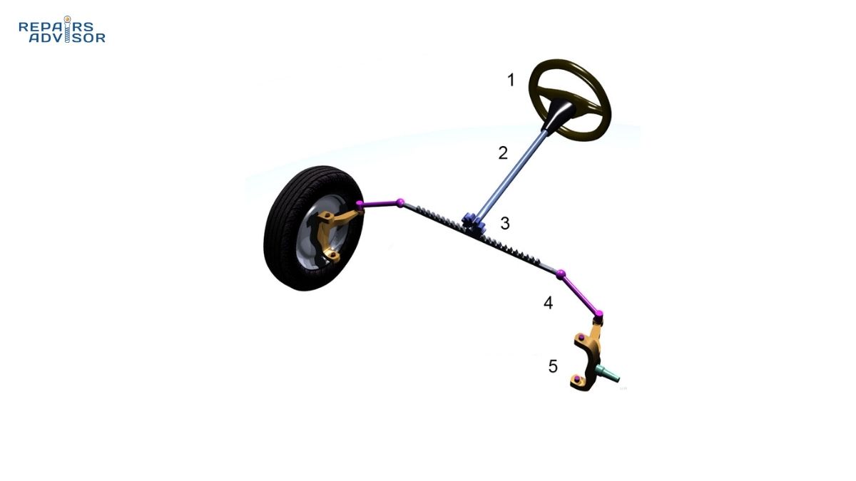
Consider what happens when you turn the steering wheel. The steering rack pushes or pulls tie rods, which rotate the steering knuckles, which pivot on ball joints connected to control arms. All of these components are part of the suspension system, and their geometric relationships determine steering behavior. If a control arm bushing wears out, it introduces unwanted movement that makes steering feel vague or imprecise. If a ball joint develops excessive play, steering becomes dangerously unpredictable.
Suspension geometry controls three critical wheel angles: camber (inward or outward tilt), caster (forward or backward tilt), and toe (direction wheels point relative to vehicle centerline). These angles change subtly as the suspension compresses and extends. Well-designed suspension minimizes unwanted changes in these angles during normal suspension travel, maintaining consistent steering feel and tire wear patterns. For professional technicians, understanding how control arm length, mounting points, and ball joint positions affect these angles throughout suspension travel is essential for diagnosing handling complaints and unusual tire wear.
Body roll during cornering introduces another steering consideration. As weight transfers to the outside tires during a turn, the suspension compresses on that side. This compression can alter wheel angles in ways that either help or hurt cornering performance. Some vehicles experience “roll understeer” where body roll causes front wheel angles to reduce steering response; others experience “roll oversteer” where suspension compression increases rear wheel steering angles. Engineers carefully design suspension geometry to create neutral or predictable roll characteristics.
Major Suspension Components and Their Construction
Understanding individual suspension components helps you diagnose problems, make repair decisions, and appreciate how everything works together. Modern suspensions contain numerous components, each engineered for specific functions.
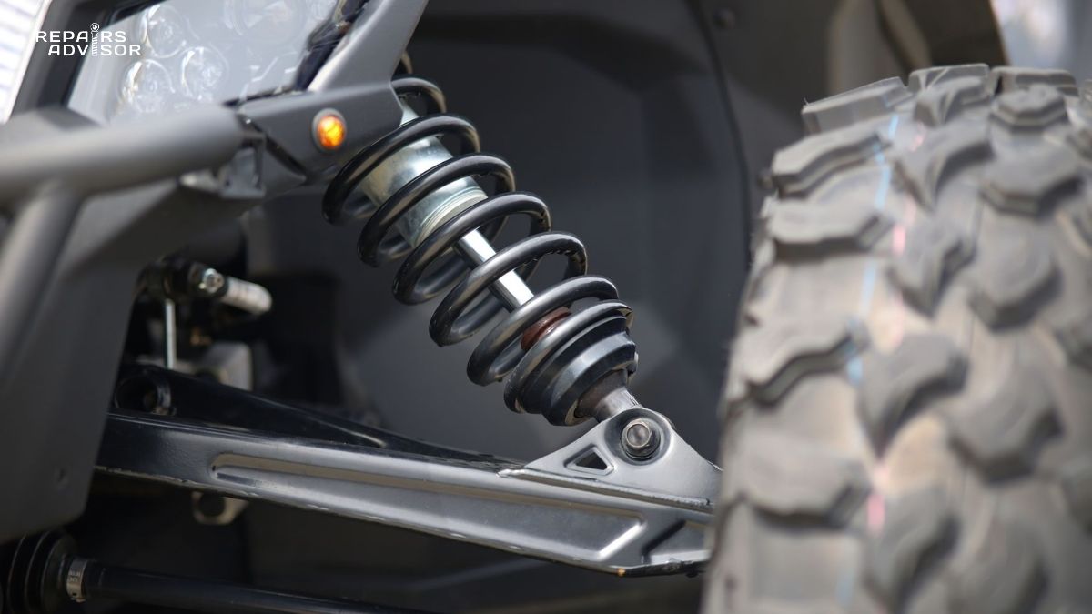
Springs: The Load Supporters and Energy Storers
Springs perform the fundamental task of supporting your vehicle’s weight while allowing vertical wheel motion. Different spring types suit different applications, each with distinct advantages and characteristics.
Coil Springs: The Modern Standard
Coil springs dominate modern automotive applications, appearing on over 80% of passenger vehicles. A coil spring is essentially a heavy-duty torsion bar wound into a helical shape. When compressed, the metal coils squeeze closer together, storing energy in the twisted steel. When released, the spring expands back to its normal length, releasing that stored energy.
Spring engineers specify coil springs by their spring rate, measured in pounds per inch (lb/in) or Newtons per millimeter (N/mm). A spring with a rate of 200 lb/in requires 200 pounds of force to compress it one inch. Stiffer springs (higher rates) resist compression more, creating firmer ride quality but better body control. Softer springs (lower rates) compress more easily, creating plusher rides but allowing more body motion.
Many modern coil springs use progressive rates rather than linear rates. A progressive spring has coils with varying spacing—as it compresses, closer-spaced coils contact each other and become inactive, effectively stiffening the spring rate. This provides soft initial response for small bumps while preventing bottoming out on large impacts. When you see a coil spring with obviously uneven coil spacing, that’s a progressive-rate design.
Coil springs rarely fail on modern passenger vehicles, often lasting 100,000+ miles. When they do fail, symptoms include sagging ride height on one corner and uneven tire wear. For detailed information on spring operation and failure modes, see our guide on How Suspension Springs Work: Load Support.
Leaf Springs: Traditional Load Champions
Leaf springs consist of multiple curved steel plates (leaves) stacked and clamped together. The traditional multi-leaf design allows each leaf to slide slightly against its neighbors as the spring flexes, providing both springing and some damping action. Modern trucks often use mono-leaf or tapered leaf designs that combine high strength with reduced weight.
Leaf springs excel at load-carrying applications, which explains their continued use on pickup trucks, heavy-duty vehicles, and older SUVs. The spring structure itself serves multiple functions: it acts as a spring, locates the axle longitudinally and laterally, and can transfer braking torque to the frame. This multi-purpose design simplifies suspension systems on load-carrying vehicles.
The downside of leaf springs compared to coil springs is ride quality and precision. The friction between leaves can cause stiction (stick-slip behavior) that makes the suspension less responsive to small bumps. Weight is another disadvantage—leaf springs are substantially heavier than equivalent coil springs. For vehicle owners with trucks using leaf springs, regular inspection for broken leaves, worn bushings at mounting points, and proper U-bolt torque prevents suspension problems. Our article on How to Tell if Your Leaf Spring is Failing covers common failure modes.
Torsion Bars: Space-Efficient Springing
A torsion bar is a straight steel bar that twists along its length to provide spring action. One end anchors rigidly to the vehicle frame, while the other end connects to a suspension control arm. As the wheel moves up and down, it rotates the control arm, which twists the torsion bar. The bar’s resistance to twisting provides the spring force.
Torsion bars offer significant packaging advantages. They’re essentially straight, so they fit easily into tight spaces alongside the frame or under the vehicle floor. This made them popular on older trucks and some front-wheel-drive vehicles where space constraints limited other spring options. Spring rate adjustments are relatively easy—rotating the anchored end of the bar changes the preload and thus the effective ride height and spring rate.
Modern applications of torsion bars have declined as engineers developed more compact coil spring designs and as ride quality expectations increased. Torsion bars generally provide slightly harsher ride quality than equivalent coil springs. However, they remain in use on some trucks and SUVs where their durability and adjustability provide advantages.
Air Springs: Adjustable Technology
Air springs replace conventional steel springs with flexible rubber bellows filled with compressed air. An onboard air compressor maintains pressure, while electronic height sensors and control valves adjust pressure to maintain desired ride height regardless of load. This adjustability represents the key advantage of air suspension—the system automatically compensates for passenger and cargo weight, maintaining consistent ride height and spring rates.
Premium luxury vehicles use air springs to provide a supremely smooth ride quality that adapts automatically to conditions. Heavy-duty trucks use air springs on rear axles to maintain level ride height when hauling heavy loads. The technology also enables ride height adjustment for different situations: raise the vehicle for off-road clearance, lower it for highway aerodynamics and easier entry.
The trade-off for this sophistication is complexity and cost. Air suspension systems include compressors, pressure reservoirs, height sensors, control valves, and electronic control units—all potential failure points. Rubber air springs can develop leaks, and compressor failures leave the vehicle sitting on bump stops. For DIY mechanics, air suspension diagnosis requires electronic scan tools to read sensor data and test solenoid valve operation. Our comprehensive guide How Air Suspension Works: Adjustable Ride Height explores these systems in detail.
If you notice sagging after the vehicle sits overnight, or hear the compressor running frequently, those are early signs of air spring leaks. Consult a qualified technician promptly—driving on failed air springs damages the metal bump stops meant only for occasional contact.
Shock Absorbers and Struts: The Dampers That Control Motion
Springs alone create a problem: they bounce. Compress a spring and release it, and it oscillates up and down repeatedly before settling. A vehicle on springs alone would bounce uncontrollably after every bump, creating a nauseating ride and dangerous loss of tire contact. Shock absorbers or struts solve this problem through damping—converting the oscillating kinetic energy into heat energy that dissipates into the air.
How Shock Absorbers Work: Hydraulic Damping
A shock absorber is fundamentally a pump that forces hydraulic fluid through restrictive passages. The typical design places a piston inside an oil-filled cylinder. As the suspension moves, the piston moves up or down inside the cylinder, forcing oil through small holes (orifices) in the piston. The resistance to oil flow creates damping force that opposes the motion.
Engineers tune shock absorbers with different orifice sizes and valve designs to control compression damping (resistance to piston movement as the suspension compresses) separately from rebound damping (resistance as the suspension extends). Typically, rebound damping is 2-3 times stiffer than compression damping. This asymmetry makes sense when you understand shock absorber function: compression damping should be relatively light to allow the suspension to absorb bumps without transmitting harshness. Rebound damping should be heavier to control the spring as it extends, preventing bounce.
Modern shock absorbers include gas pressure systems (gas shocks) where pressurized nitrogen in a separate chamber or behind a floating piston prevents oil aeration (foaming) during hard use. When oil foams, it becomes compressible, and the shock temporarily loses damping force—a phenomenon called shock fade that manifests as degraded ride quality after rough road sections. Gas pressure keeps oil under constant pressure, preventing aeration even during demanding conditions.
Shock absorbers typically last 50,000-100,000 miles depending on driving conditions. Visual signs of failure include oil leaking from the shaft seal or body. Functional symptoms include excessive bouncing after bumps, nose dive during braking, and body roll during cornering. The classic shock test: push down hard on a corner of the vehicle and release. If the vehicle bounces more than 1-2 times before settling, the shock is likely worn. For detailed diagnostic procedures, see How to Tell if Your Front Shock Absorber Is Failing.
Our technical article How Shock Absorbers and Struts Work: Damping Control provides deeper insight into damping theory and shock absorber design variations.
Struts vs. Shock Absorbers: Structural Differences
The term “shock absorber” often gets used generically, but struts and shock absorbers differ significantly in design and function. A shock absorber is a stand-alone damper that doesn’t carry vehicle weight or provide structural support. It connects between the suspension and body/frame only to control motion. The suspension spring mounts separately around the shock or on a different location entirely.
A strut, by contrast, is a structural suspension component that combines damping function with structural support. The most common design, the MacPherson strut, contains the shock absorber mechanism inside a tube that serves as a load-bearing member. The coil spring typically mounts concentrically around the strut body. The top of the strut bolts to a strut mount bearing that allows rotation for steering, while the bottom connects to the steering knuckle. The strut forms one leg of the suspension triangle, replacing an upper control arm.
This structural difference has important implications. Because struts carry vehicle weight and steering loads, they affect wheel alignment. Worn struts can allow wheel alignment to shift, causing steering pull and uneven tire wear. When you replace struts, wheel alignment is mandatory. Shock absorbers don’t affect alignment, so shock replacement doesn’t require alignment unless other suspension components are disturbed.
The MacPherson strut design offers significant advantages for vehicle packaging. By eliminating the upper control arm and combining the spring and shock into a single assembly, MacPherson struts save space, weight, and cost. This explains why the design appears on roughly 70% of modern front-wheel-drive vehicles. The trade-off is slightly less precise control of wheel geometry compared to double-wishbone designs with separate shocks. For detailed exploration of MacPherson strut design, see How MacPherson Strut Suspension Works: Compact Design.
Safety Warning: Strut and shock absorber replacement requires proper tools and procedures. Coil springs store tremendous energy—improper handling can cause the spring to violently release, resulting in severe injury or death. Always use appropriate spring compressors and follow manufacturer procedures. This is not a beginner-level task, and many experienced DIY mechanics choose to have struts professionally replaced due to the safety risks involved.
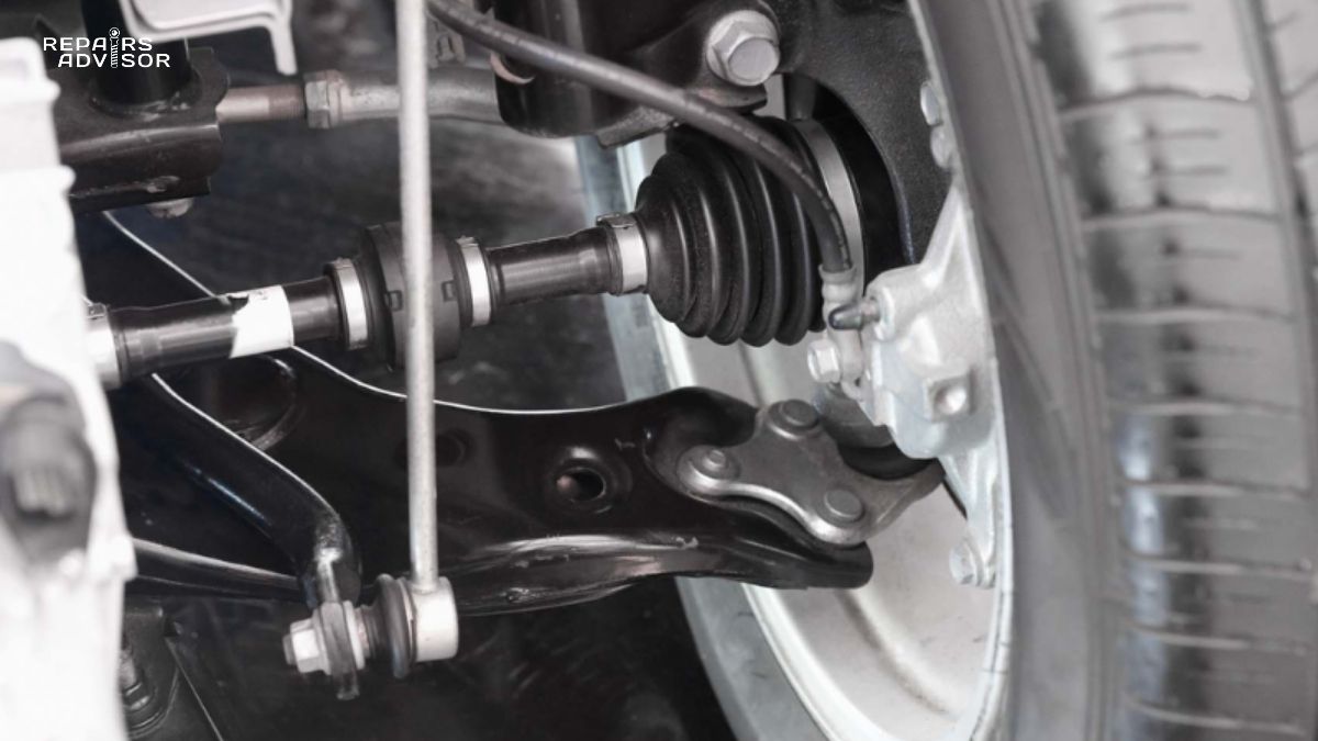
Control Arms: The Geometry Controllers
Control arms (also called A-arms or wishbones due to their shape) connect the wheel hub assembly to the vehicle body or frame. They allow vertical wheel movement while maintaining proper wheel alignment and controlling suspension geometry. The design, length, and mounting angles of control arms fundamentally determine how suspension behaves.
Single vs. Double Control Arm Designs
Vehicles use different control arm configurations depending on suspension design. MacPherson strut suspensions typically use a single lower control arm per wheel, with the strut replacing the upper control arm function. Double-wishbone suspensions use both upper and lower control arms, with the shock absorber and spring mounted separately.
The double-wishbone design offers superior control of wheel geometry. By carefully positioning the upper and lower control arm pivot points and lengths, engineers can precisely control how camber, caster, and toe angles change throughout suspension travel. This explains why high-performance vehicles and luxury cars often use double-wishbone designs despite their higher cost and packaging challenges. Multi-link suspensions take this concept further, using 4-5 separate links per wheel to enable even more precise geometry control.
For comprehensive details on control arm function and design variations, see our article How Control Arms Work: Suspension Geometry.
Ball Joints: The Pivot Points
Control arms connect to the steering knuckle through ball joints—precision pivot points that allow rotation in multiple axes while maintaining tight tolerances. A ball joint consists of a hardened steel ball stud inserted into a lubricated bearing socket, all enclosed in a protective boot filled with grease.
Most vehicles use both upper and lower ball joints in double-wishbone configurations, or a single lower ball joint in MacPherson strut designs. These joints must support vehicle weight (load-bearing joints) while allowing smooth multi-axis rotation for steering and suspension travel. The ball stud pivots with very little friction or play—excessive play indicates wear and requires immediate replacement.
Ball joint failure represents a serious safety hazard. A separated ball joint allows the wheel to collapse outward, causing immediate loss of control. For this reason, ball joints receive close attention during safety inspections. Professional technicians use dial indicators to measure radial and axial play, comparing measurements to manufacturer specifications. Typical wear limits are 0.050 inches or less of radial play. Beyond that threshold, replacement is mandatory.
Common ball joint wear symptoms include clunking noises when going over bumps, steering that feels loose or vague, and uneven tire wear. For detailed diagnostic guidance, see How to Tell if You Have a Bad Ball Joint (and Why It’s a Big Deal!). Our technical article How Ball Joints Work: Pivot Points explains ball joint design and lubrication systems.
When to Consult a Professional: Ball joint replacement requires specialized tools to press joints in and out of control arms or steering knuckles. The work affects safety-critical suspension components and requires proper torque specifications and sometimes alignment adjustments. Unless you have professional-level tools and experience, ball joint replacement should be left to qualified technicians.
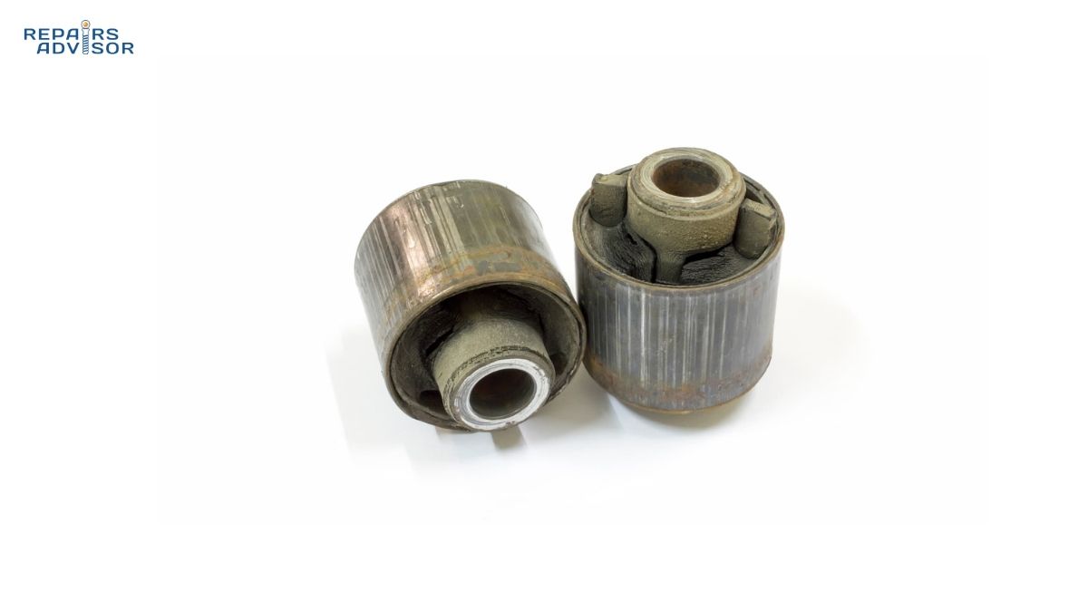
Bushings: Compliance and Vibration Isolation
At each end of a control arm, where the arm mounts to the frame or subframe, you’ll find a bushing—a flexible isolator that allows controlled movement while absorbing vibration and noise. Most bushings use rubber bonded between inner and outer metal sleeves. The rubber provides both compliance (allowing the control arm to move through its arc) and isolation (preventing vibration transmission to the chassis).
Bushing design represents another suspension compromise. Soft rubber bushings provide excellent ride comfort and noise isolation but allow more suspension deflection under load, which can make steering feel less precise. Harder rubber or polyurethane bushings reduce deflection for sharper steering response but transmit more noise and vibration. High-performance vehicles often use hydraulic bushings that contain fluid-filled chambers for optimal control of both compliance and damping.
Control arm bushings gradually deteriorate from age, heat, oil contamination, and repeated flexing cycles. Failed bushings exhibit torn rubber, visible cracks, or separation between rubber and metal. Symptoms include clunking noises over bumps, steering that feels imprecise or wandering, and vibration transmitted through the chassis. Uneven tire wear, particularly feathering (one edge of each tread block worn more than the other), can indicate bushing wear allowing excessive toe change.
For intermediate DIY mechanics, visual bushing inspection is straightforward—look for obvious deterioration with the vehicle on a lift or jack stands. However, some bushing wear only becomes apparent under load. Professional shops use pry bars to load suspension components while checking for excessive movement at bushing locations.
Detailed information on bushing function, wear patterns, and diagnosis appears in our article How Control Arm Bushings Work: Compliance and Isolation. For diagnostic guidance, see How to Tell if You Have a Bad Control Arm Bushing.
Stabilizer Bars: The Body Roll Controllers
Stabilizer bars (also called anti-roll bars or sway bars) serve a specific function: reducing body roll during cornering without affecting ride quality over straight-line bumps. A stabilizer bar is a torsion bar that connects the left and right suspension. When both wheels move together (straight-line bump), the bar simply rotates in its mounting bushings with minimal resistance. When one wheel moves independently (body roll during cornering), the bar resists by twisting, effectively adding spring rate to limit body roll.
The genius of this design is that it targets only the specific motion you want to control—body roll—without stiffening the suspension for straight-line bumps. Engineers can tune body roll control independently from ride comfort by selecting appropriate stabilizer bar diameter and mounting geometry. Thicker bars provide more roll resistance; adjustable end links allow fine-tuning of bar effectiveness.
Most vehicles use front and rear stabilizer bars, though some basic economy models omit the rear bar to reduce costs. The ratio of front-to-rear stabilizer bar stiffness affects handling balance—stiffer front bar relative to rear induces understeer (front tire slip), while stiffer rear bar relative to front induces oversteer (rear tire slip). Performance vehicles use this front/rear ratio as a primary handling tuning parameter.
Stabilizer bar bushings and end links are common wear items. The bar must rotate in its frame-mounted bushings during suspension travel, and these bushings deteriorate from constant motion and exposure to road contaminants. Failed bushings create clunking noises over bumps and during body roll. End links (the connections from bar to suspension) use ball-and-socket joints that can wear and create similar noises.
For diagnostic procedures and symptoms, see How to Tell if Your Front Sway Bar is Failing.
Supporting Components: The Critical Details
Several additional components complete the suspension system, each vital to proper operation.
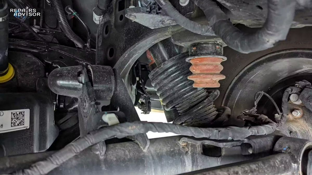
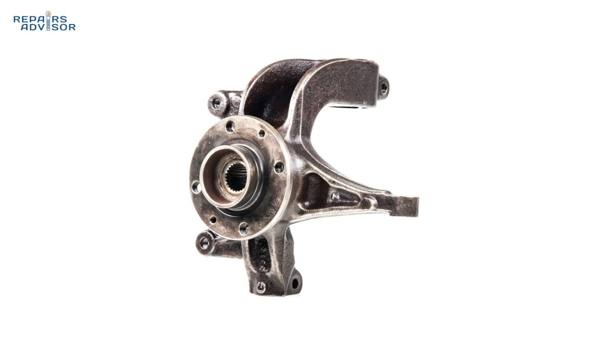
Steering Knuckles: The steering knuckle (also called the spindle or upright) is the component that actually carries the wheel hub assembly and provides mounting for the brake caliper. The knuckle connects to control arms through ball joints and to the steering system through the tie rod. For detailed examination of knuckle design and function, see How Steering Knuckles Work: Wheel Support.
Bump Stops: These polyurethane or rubber stops limit suspension travel at full compression, preventing metal-to-metal contact between suspension components and the chassis. Progressive bump stops gradually increase resistance as compression increases, providing a soft limit rather than a harsh stop. Failed bump stops can allow suspension components to bottom out violently on large bumps, potentially causing damage. See How Bump Stops Work: Suspension Travel Limiting for more information.
Wheel Bearings: While often considered separate from the suspension, wheel bearings work closely with suspension components. These precision bearings allow wheels to rotate with minimal friction while supporting vehicle weight and suspension loads. Worn wheel bearings create noise (growling or humming that changes with speed) and can develop play that affects wheel alignment. Our guide How Wheel Bearing Systems Work: Load Support & Rotation covers bearing design and diagnostics.
Types of Suspension Systems
Suspension systems fall into three broad categories based on how the left and right wheels interact: independent, dependent, and semi-independent. Each category suits different applications and offers distinct advantages.
Independent Suspension: Maximum Wheel Control
Independent suspension allows each wheel to move vertically without directly affecting the opposite wheel on the same axle. When the left front wheel hits a bump, it moves upward independently while the right front wheel maintains its position (assuming the right side isn’t also encountering the bump). This independence provides superior ride quality, handling, and tire contact consistency.
The key advantage of independent suspension becomes obvious on uneven surfaces. Consider driving with the right tires on pavement and left tires on a gravel shoulder. With independent suspension, each wheel follows its terrain independently, maintaining optimal contact and control. With dependent suspension (solid axle), lifting one wheel necessarily affects the other.
Modern passenger vehicles overwhelmingly use independent suspension on all four wheels. The design enables better packaging (no axle tube occupying space), reduced unsprung weight (lighter moving components), and superior ride quality. The trade-off is increased complexity and cost—independent suspension requires more components and more intricate engineering than simpler solid axle designs.
MacPherson Strut: The Compact Favorite
MacPherson strut suspension dominates modern front-wheel-drive vehicles due to its compact, cost-effective design. The strut itself forms one side of the suspension triangle, with a single lower control arm completing the geometry. This minimal component count saves weight, space, and manufacturing cost while providing perfectly adequate performance for most applications.
The MacPherson design locates the spring and shock coaxially (on the same axis) with the strut tube forming a structural member. The top mounts to the chassis through a strut mount bearing that allows rotation for steering. The bottom bolts to the steering knuckle. The single lower control arm pivots on frame-mounted bushings, with a ball joint connecting the arm to the steering knuckle.
Advantages include simplicity (fewer parts), compact packaging (leaves more room for engine and drivetrain), light weight, and low cost. The main disadvantage is less precise control of wheel geometry compared to double-wishbone designs. As the wheel moves through its travel, camber changes more dramatically with MacPherson struts than with optimized double-wishbone geometries. For most drivers in most situations, this geometric compromise is imperceptible. Performance enthusiasts often prefer double-wishbone designs for their superior geometry control.
For detailed exploration of MacPherson strut design, geometry, and advantages, see How MacPherson Strut Suspension Works: Compact Design.
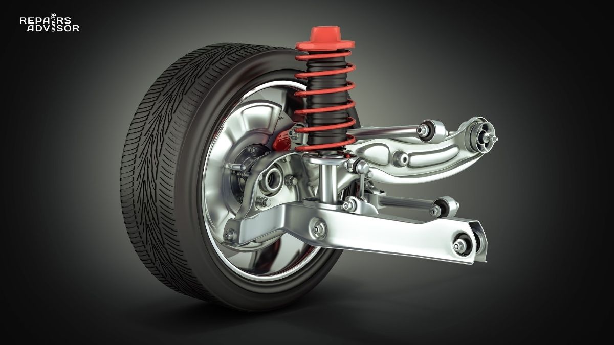
Double Wishbone: The Performance Standard
Double-wishbone suspension (also called A-arm or SLA—short-long arm) uses both upper and lower control arms to locate the wheel, with the shock absorber and spring mounted separately. This configuration provides maximum flexibility in suspension geometry design. By carefully positioning the pivot points for upper and lower arms and selecting appropriate arm lengths, engineers can create virtually any desired camber curve (how camber changes throughout suspension travel).
High-performance vehicles, luxury cars, and racing vehicles favor double-wishbone designs because they enable superior handling precision. The separate spring/shock mounting allows engineers to position these components optimally for best motion ratios and packaging. The design also typically exhibits better camber control during cornering—the outside wheel maintains more negative camber under body roll, maximizing tire contact patch and grip.
The disadvantages are cost, weight, and packaging challenges. Double-wishbone suspension requires more parts than MacPherson struts, costs more to manufacture, and occupies more space. These trade-offs are acceptable for vehicles where handling precision justifies the extra expense, but they make double-wishbone suspension rare in economy vehicles.
Our article How Double Wishbone Suspension Works: Superior Control explores the geometry and tuning possibilities this design enables.
Multi-Link: The Ultimate Precision
Multi-link suspension takes the concept of control arm geometry even further by using 4-5 separate links per wheel. Each link controls a specific aspect of wheel motion—some control camber, others control toe, still others manage longitudinal location. This granular control enables engineers to create suspension behavior that would be impossible with simpler designs.
High-end luxury vehicles and performance cars use multi-link rear suspension to provide optimal wheel control without the packaging constraints of front suspension (no steering rack to accommodate). The design delivers exceptional ride quality combined with precise handling—the links can be tuned to minimize unwanted geometry changes during suspension travel while maintaining excellent body roll control.
For deep technical details, see How Multi-Link Suspension Works: Advanced Dynamics.
Dependent Suspension: Simplicity and Strength
Dependent suspension connects both wheels on an axle with a solid axle beam. When one wheel moves vertically, it directly affects the other wheel. This design seems primitive compared to independent suspension, but it offers significant advantages in specific applications that explain its continued use on trucks, SUVs, and off-road vehicles.
The primary advantages are simplicity, strength, and load-carrying capability. A solid axle is mechanically simple—few parts mean fewer potential failure points. The design is extremely strong and can handle heavy loads without the geometric complexities and potential deflection issues of independent suspension with multiple links and pivots. For vehicles that tow heavy trailers or carry substantial cargo, solid axle rear suspension remains common.
The disadvantage is ride quality and handling on uneven surfaces. When one wheel encounters a bump, it lifts the entire axle, affecting the opposite wheel even if that side is on smooth pavement. This creates a less comfortable ride and reduces tire contact consistency compared to independent designs. Body roll control is also more challenging—solid axles tend to allow more body roll for a given spring rate compared to independent suspensions with effective anti-roll bars.
Two solid axle variations exist: live axle and De Dion axle. A live axle mounts the differential directly to the axle beam, so the differential moves with the wheels—this adds unsprung weight and can contribute to wheel hop under hard acceleration or on rough roads. A De Dion axle mounts the differential to the chassis with only the axle shafts and wheel ends as unsprung weight—this reduces unsprung weight but adds complexity. Live axles are far more common due to their simplicity.
Vehicles with solid rear axles typically use leaf springs or coil springs with trailing arms and a Panhard rod for lateral location. The combination provides adequate ride quality for truck applications while maintaining the load-carrying and towing advantages of solid axle design.
If your vehicle uses leaf springs, regular inspection prevents problems. See How to Tell if Your Leaf Spring is Failing for diagnostic guidance.
Semi-Independent Suspension: The FWD Compromise
Semi-independent suspension, specifically the torsion beam or twist beam design, represents a middle ground between fully independent and dependent suspension. This design appears almost exclusively on the rear axle of front-wheel-drive vehicles, where cost and packaging constraints make it attractive.
The torsion beam suspension uses two trailing arms (one per wheel) connected by a torsion beam that twists to allow some independent wheel movement while maintaining a mechanical connection between sides. When one wheel encounters a bump, it moves upward. The trailing arm on that side rotates, twisting the connecting beam, which provides some spring action and limits how much the opposite wheel is affected. The design isn’t fully independent (there is mechanical coupling through the beam), but it’s not fully dependent either—it’s semi-independent.
Advantages include simplicity (fewer parts than multi-link independent suspension), compact packaging (fits easily in space-constrained FWD vehicle rear ends), low cost, and acceptable ride quality for most drivers. The disadvantages are less precise handling than fully independent rear suspension and somewhat limited wheel travel compared to multi-link designs.
For detailed explanation of torsion beam design and operation, see How Rear Torsion-Beam Suspension Works: FWD Architecture.
Step-by-Step: How Suspension Absorbs a Bump
Understanding the sequence of events when your tire encounters a road irregularity illuminates how suspension components work together to isolate the vehicle body from road impacts.
The Impact Sequence
Step 1: Tire Encounters Bump
Your tire contacts a road imperfection—a pothole edge, expansion joint, or piece of debris. The tire itself provides the first level of suspension by deflecting and absorbing some impact energy. A properly inflated tire with compliant sidewalls significantly reduces the impact transmitted to the wheel and suspension. This explains why correct tire pressure matters—overinflated tires transmit more impact harshness, while underinflated tires flex excessively and can bottom out on wheel rims.
Step 2: Vertical Force Transmits Through Wheel Bearing
The impact force transmits from the tire through the wheel bearing into the hub, which is attached to the steering knuckle. The wheel bearing must handle this vertical shock load while maintaining low-friction rotation. Worn wheel bearings with excessive play allow the wheel to move irregularly, creating noise and vibration.
Step 3: Control Arms Guide Wheel Travel
As the wheel moves upward, the control arms guide its motion in a controlled arc. The ball joints at each end of the control arm pivot to allow this motion while maintaining the connection between the knuckle and control arm. Well-designed suspension geometry minimizes changes in wheel camber (tilt) and toe (direction) during this vertical travel, keeping the tire properly oriented to the road surface.
The bushings at the control arm’s chassis mounting points allow the arm to rotate through its arc while also absorbing some vibration. Worn bushings create excessive deflection that makes the suspension feel loose and imprecise.
Step 4: Spring Compresses and Stores Energy
The upward wheel motion compresses the coil spring (or compresses an air spring, or twists a torsion bar—the principle is the same). The spring resists compression with a force proportional to its spring rate. If the spring rate is 200 lb/in and the wheel moves up 2 inches, the spring pushes back with 400 pounds of force.
The spring temporarily stores the impact energy as potential energy in the compressed or twisted metal (or compressed air). Without this energy storage, the impact would transmit directly to the vehicle body. For professional technicians, the spring rate directly determines ride frequency—how quickly the suspension oscillates. Typical passenger car ride frequencies range from 1.0-1.5 Hz (cycles per second), which extensive research has shown provides the optimal balance between comfort and control for most applications.
Step 5: Shock Absorber Controls Spring Motion
As the spring compresses, the shock absorber’s piston moves through the hydraulic fluid inside the shock body. The fluid must flow through restrictive orifices in the piston, creating resistance that opposes the compression motion. This compression damping prevents the spring from compressing too quickly, which would transmit a harsh jolt to the vehicle body.
The shock absorber converts the kinetic energy of suspension motion into heat energy through fluid friction. The shock body becomes warm during hard use—this is normal and expected. The damping force depends on piston velocity, not position—the shock provides more resistance during rapid motion and less resistance during slow motion. This velocity-dependent damping is ideal for suspension control.
Step 6: Spring Rebounds in Controlled Manner
Once the wheel passes the bump, the compressed spring begins to extend back toward its normal length, releasing the stored energy. Without the shock absorber, the spring would extend rapidly and overshoot its normal length, causing the vehicle to bounce upward. The wheel would then drop back down, compressing the spring again, leading to repeated oscillation (bouncing) that continues for several cycles.
The shock absorber’s rebound damping controls this extension, slowing it to a controlled rate. Rebound damping is typically 2-3 times stiffer than compression damping because controlling spring extension is critical to preventing bounce. The shock allows the spring to return to its normal length at a controlled rate without oscillation.
Step 7: System Returns to Equilibrium
The suspension settles back to its normal ride height, with the spring supporting the vehicle weight at its design position and the shock absorber at rest. The entire sequence typically completes in 0.5-1.5 seconds depending on bump severity and suspension tuning. The vehicle body experiences minimal vertical acceleration—passengers feel a slight motion but nothing approaching the actual impact magnitude the tire experienced.
For beginner enthusiasts, the key takeaway is that springs and shocks work together—springs support weight and absorb impacts, shocks control the springs’ motion to prevent bouncing. Neither component works effectively alone.
What Happens During Cornering: Weight Transfer Dynamics
The same suspension components that absorb bumps also manage vehicle dynamics during cornering, braking, and acceleration. Understanding weight transfer helps explain why suspension tuning affects handling.
When you turn the steering wheel and begin cornering, inertia creates a lateral force that pushes the vehicle body toward the outside of the turn. The vehicle wants to continue traveling in a straight line; the tires create lateral force to change direction, but this force manifests as body roll—the outside suspension compresses while the inside suspension extends.
This weight transfer loads the outside tires more heavily while unloading the inside tires. The outside tire contact patches increase in size and generate more grip; inside tire contact patches decrease and lose grip. The anti-roll bar resists this roll by connecting the left and right suspension. As the outside compresses, the bar twists, lifting the inside suspension and reducing the amount of roll.
The balance between front and rear suspension stiffness (including anti-roll bar stiffness) determines handling characteristics. If the front suspension is relatively stiffer than the rear, weight transfer is less at the front, so the front tires maintain more consistent contact patches and grip. This creates understeer—the front tires break loose before the rear, making the vehicle resist turning. If the rear is relatively stiffer, the rear tires break loose first, creating oversteer—the rear of the vehicle swings outward.
Professional suspension tuners manipulate front/rear roll stiffness distribution to create desired handling balance. Most passenger vehicles are tuned for mild understeer because it’s safer—the average driver reacts better to understeer (vehicle doesn’t turn enough) than oversteer (vehicle turns too much, potentially spinning).
Suspension and Steering Integration
The suspension system and steering system are inseparably linked. Understanding their interaction helps explain why suspension problems often manifest as steering issues.
Steering Geometry Fundamentals
Three primary angles define wheel orientation: camber, caster, and toe. These angles are adjustable through alignment procedures and critical to proper vehicle handling.
Camber describes the inward or outward tilt of the top of the tire when viewed from the front. Negative camber means the top tilts inward; positive camber means it tilts outward. Most vehicles use slight negative camber (0.5-1.5 degrees) to optimize tire contact during cornering. As the vehicle body rolls, negative camber helps keep the tire flatter on the road surface. Excessive camber in either direction causes rapid tire wear on one edge.
Caster describes the fore-aft tilt of the steering axis when viewed from the side. Positive caster means the top of the steering axis tilts rearward. Caster provides steering stability—it makes the wheels want to return to center after a turn, similar to how a shopping cart caster self-centers. Most vehicles use 3-8 degrees of positive caster. Insufficient caster makes steering feel unstable and wandering.
Toe describes whether the fronts of the tires point inward (toe-in) or outward (toe-out) when viewed from above. Most vehicles use slight toe-in (0.05-0.20 degrees total) to promote stability. Toe settings significantly affect tire wear—excessive toe in either direction causes rapid feathering wear across the tire tread.
These angles change subtly as suspension compresses and extends. Well-designed suspension minimizes unwanted changes to maintain consistent handling. Our comprehensive guide How Wheel Alignment Works: Geometry and Angles explores these concepts in detail.
The Steering System Connection
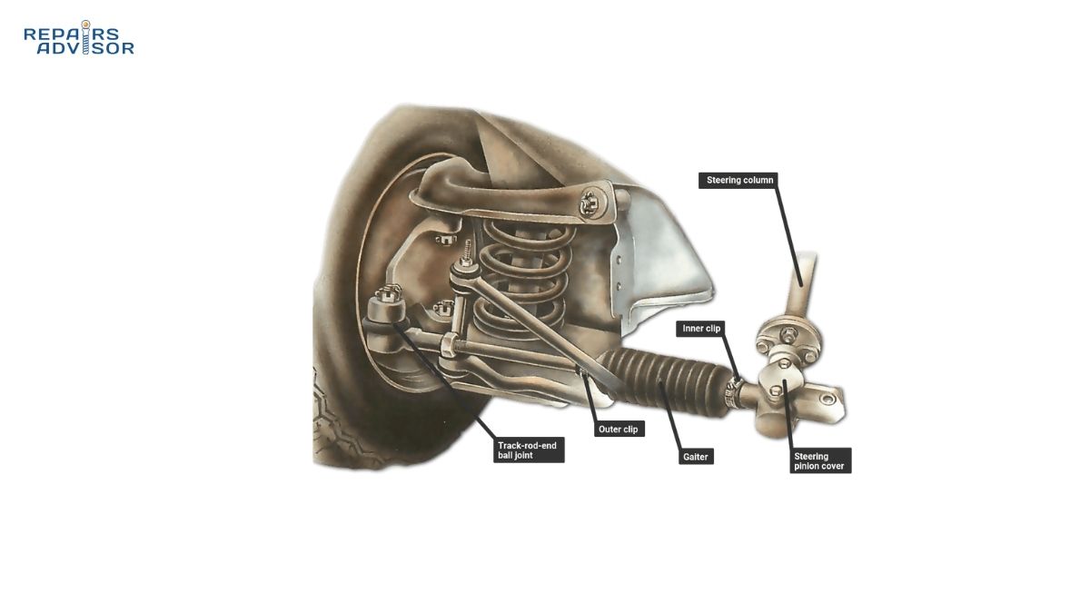
The steering system mechanically connects to the suspension at the tie rods, which link the steering rack to the steering knuckles. When you turn the steering wheel, the steering rack moves laterally, pushing or pulling the tie rods, which rotate the steering knuckles about the ball joint pivot points. This rotation steers the wheels.
The suspension must allow this steering motion while also permitting vertical wheel travel over bumps. The ball joints provide the multi-axis pivot capability that enables both motions simultaneously. The tie rod ends include ball-and-socket joints for the same reason—they must accommodate both steering rotation and suspension vertical motion.
Worn suspension components affect steering feel and precision. Worn ball joints create play that makes steering feel vague and imprecise. Worn control arm bushings allow the entire control arm to deflect under cornering loads, changing wheel alignment dynamically and making the vehicle feel unstable. Failed tie rod ends create similar play directly in the steering connection.
For diagnostic guidance on tie rod ends, see Inner Tie Rod End: Complete Diagnostic and Replacement Guide. For steering system fundamentals, see How Rack and Pinion Steering Works: Precision Control and How Steering Columns Work: Connection and Safety.
Unsprung vs. Sprung Weight: A Critical Design Parameter
Engineers divide vehicle weight into two categories: sprung weight (everything supported by the suspension, including body, frame, engine, passengers, and cargo) and unsprung weight (everything that moves with the wheels, including wheels, tires, brakes, hubs, and suspension components below the springs).
Unsprung weight directly affects ride quality and tire contact. When a wheel encounters a bump, the unsprung mass must accelerate vertically to follow the road contour. Light unsprung weight accelerates easily with minimal force, keeping the tire in better contact with the road. Heavy unsprung weight resists acceleration, causing the tire to lose contact momentarily.
This explains many suspension design decisions. Aluminum control arms replace heavier steel to reduce unsprung weight. Multi-link suspension allows springs and shocks to mount inboard (to the chassis) rather than directly on the suspension components, keeping them as sprung rather than unsprung weight. The De Dion rear axle design moves the differential from the axle to the chassis specifically to reduce unsprung weight.
For professional engineers and serious enthusiasts, a useful rule of thumb is that reducing one pound of unsprung weight provides handling benefits equivalent to reducing 10-15 pounds of sprung weight. This explains why high-performance vehicles invest heavily in lightweight wheels, brakes, and suspension components.
Signs Your Suspension Needs Attention
Recognizing suspension problems early prevents safety hazards, reduces repair costs, and maintains vehicle performance. Different skill levels can identify different symptoms.
Beginner-Level Warning Signs
Even if you’re not mechanically inclined, several obvious symptoms indicate suspension problems requiring immediate attention.
Excessive Bouncing: If your vehicle bounces more than 1-2 times after hitting a bump or after you push down on a corner and release, the shock absorbers or struts are worn. The vehicle should settle quickly without oscillating. Excessive bouncing indicates the shocks have lost damping force and can no longer control the springs effectively. This significantly reduces vehicle control, especially during emergency maneuvers.
Nose Dive During Braking: When you apply the brakes, some forward weight transfer is normal—you’ll feel the front end compress slightly. However, if the front end dips dramatically or continues compressing excessively, worn front shocks or struts are failing to control weight transfer. This not only feels uncomfortable but also reduces braking effectiveness by decreasing rear tire contact.
Vehicle Sits Lower on One Corner: If one corner of your vehicle sits noticeably lower than the others, a spring has likely failed or a strut/shock has collapsed. Measure the vehicle height at each wheel center from the ground to the fender lip and compare side-to-side and front-to-rear. More than a half-inch difference indicates a problem. A failed spring requires immediate attention—the vehicle is no longer level, affecting handling and tire wear.
Squeaking, Clunking, or Knocking Noises: Strange noises over bumps or during turns often indicate worn suspension components. Squeaks typically come from dry or deteriorated bushings. Clunks suggest loose or worn components like ball joints, control arm bushings, or stabilizer bar links. Knocking during turns can indicate failed strut mount bearings. Don’t ignore suspension noises—they indicate components operating outside normal parameters and often precede complete failure.
Safety Warning: If you experience any of these symptoms, have your suspension inspected by a qualified technician immediately. Worn suspension components compromise vehicle control, increase stopping distances, and in severe cases can cause sudden component failure leading to loss of control. Your safety and the safety of others depends on a functional suspension system.
Intermediate-Level Diagnostic Signs
DIY enthusiasts with some mechanical knowledge can identify additional suspension problems through more detailed observation.
Uneven Tire Wear Patterns: Your tires reveal suspension and alignment problems through their wear patterns. Excessive wear on the inner or outer edge indicates camber misalignment often caused by worn suspension components. Feathering (one side of each tread block worn more than the other) indicates toe misalignment. Cupping (scalloped dips around the tire circumference) typically indicates worn shock absorbers allowing the tire to bounce and skip contact with the road. Examine all four tires for unusual wear patterns—they tell the story of suspension geometry and condition.
Steering Wheel Vibration: While tire balance issues cause the most common steering wheel vibrations, suspension problems can also transmit vibrations. Worn tie rod ends create vibration during acceleration or braking as they allow slight motion in the steering linkage. Failed control arm bushings can transmit road vibration directly to the chassis and steering column. Paying attention to when vibration occurs helps identify the source—constant vibration at certain speeds suggests balance issues, while vibration during specific maneuvers suggests suspension or steering component wear.
Oil Leaks on Shock Absorber Bodies: Shock absorbers contain hydraulic fluid sealed by a shaft seal where the piston rod exits the body. As shocks age, this seal wears and begins leaking oil, visible as wet residue on the shock body or strut tube. Some slight seepage (a thin film of oil) is normal on older shocks, but visible oil drips or heavy accumulation indicates failed seals and lost damping function. Replace shocks in pairs (both front or both rear) to maintain consistent damping on both sides.
Steering Pull or Drift: If your vehicle pulls consistently to one side or drifts (wanders from straight ahead) despite proper alignment, suspension problems may be the cause. Uneven suspension sag from a weakening spring can cause pull. Worn control arm bushings allow dynamic geometry changes that make the vehicle drift. Failed shock absorbers on one side create asymmetric weight transfer that pulls toward the side with more effective damping.
Difficulty Steering or Increasing Steering Effort: While power steering problems cause most steering effort issues, suspension binding can also increase steering effort. Seized ball joints or extremely deteriorated control arm bushings can restrict suspension motion, making the steering feel stiff, especially at low speeds in parking lots where suspension articulation is greatest.
Professional-Level Assessment Techniques
Professional technicians use specialized tools and procedures to quantify suspension condition and identify problems not obvious through visual inspection or test drives.
Alignment Angle Measurements: Computerized alignment equipment measures camber, caster, and toe angles precisely and compares them to manufacturer specifications. Angles outside specifications indicate worn or damaged suspension components. But professional technicians look beyond just in-spec or out-of-spec—they examine the pattern of angle deviations to diagnose specific component failures. For example, excessive positive camber on one side combined with reduced caster on that same side suggests a failed upper control arm bushing allowing the control arm to shift position.
Ball Joint Play Measurement: Professionals use dial indicators to measure ball joint play with the suspension loaded and unloaded. The measurement procedure depends on suspension design—load-bearing ball joints must be measured with weight on or off depending on their orientation. Typical wear limits are 0.050 inches radial play or 0.030 inches axial play, though specifications vary by manufacturer. Exceeding these limits requires immediate ball joint replacement.
Control Arm Bushing Deflection Checks: Using large pry bars, technicians load suspension components in various directions while measuring movement at bushing locations. Excessive deflection indicates bushing deterioration. This test requires experience to interpret—some deflection is normal compliance, while excessive deflection indicates failure. The test must compare side-to-side for symmetry—asymmetric deflection indicates a problem on one side.
Shock Absorber Dyno Testing: Professional shock absorber test equipment measures actual damping force at various piston speeds and compares results to manufacturer specifications. This objective test identifies shocks that have lost damping force even when visual and bounce tests aren’t conclusive. Many quick-lube and tire shops offer shock testing as part of routine inspections.
For comprehensive diagnostic procedures on specific components, see How to Spot a Bad Control Arm and How to Spot a Bad Front Coil Spring.
Typical Suspension Component Lifespans
Understanding normal component life helps you plan maintenance and budget for eventual replacement.
Shock Absorbers and Struts: 50,000-100,000 miles depending on driving conditions. Rough roads, frequent load carrying, and aggressive driving reduce lifespan. Many manufacturers recommend inspection at 50,000 miles and replacement by 100,000 miles even if no obvious symptoms are present—shocks deteriorate gradually and you may not notice the performance degradation until new shocks restore full performance.
Springs: Coil springs rarely fail on passenger vehicles and often last the vehicle’s lifetime. When springs do fail, it’s typically from corrosion in road salt environments or from overload (regularly exceeding weight ratings). Air springs in air suspension systems have shorter lifespans, typically 60,000-120,000 miles before developing leaks.
Control Arm Bushings: 70,000-150,000 miles. Heat, oil contamination, and suspension articulation gradually deteriorate rubber bushings. Polyurethane bushings last longer but transmit more noise and vibration. Hydraulic bushings can last 100,000+ miles if not contaminated.
Ball Joints: 70,000-150,000 miles. Sealed ball joints that require no maintenance last longer than serviceable joints requiring periodic greasing. Heavy loads, rough roads, and exposure to road salt and contaminants reduce lifespan. Many manufacturers now use sealed-for-life ball joints integrated into control arms, requiring complete control arm replacement when the joint fails.
Anti-Roll Bar Links and Bushings: 50,000-100,000 miles. The constant articulation and exposure to contaminants wears these components relatively quickly. Links are inexpensive and straightforward to replace, making them a common maintenance item.
These lifespans represent averages—your specific results depend on driving conditions, vehicle weight, suspension design, and maintenance practices. Vehicles driven primarily on smooth highways last longer than vehicles on rough urban roads. Proper wheel alignment and avoiding overload extend suspension component life.
When to Consult a Professional
While understanding suspension symptoms helps you identify problems, many suspension issues require professional diagnosis and repair.
Safety-Critical Symptoms Requiring Immediate Attention:
- Any pulling or instability during braking
- Clunking or knocking that seems to come from suspension during turning
- Visible damage to suspension components
- Steering that feels loose, with excessive play in the steering wheel
- Vehicle that sits noticeably lower on one corner
- Any symptom that affects your ability to control the vehicle
Regular Preventive Inspection Schedule:
- First inspection at 50,000 miles even without symptoms
- Follow-up inspections every 50,000 miles or as recommended by your vehicle manufacturer
- Inspection after any impact (pothole, curb, collision)
- Inspection when replacing tires (examine for unusual wear patterns that indicate suspension problems)
Before Attempting DIY Suspension Work:
- Understand that suspension work requires proper safety equipment including heavy-duty jack stands, spring compressors, and torque wrenches
- Recognize that spring compression stores tremendous energy that can cause severe injury if improperly handled
- Know that most suspension work requires wheel alignment afterward, which requires professional equipment
- Accept that safety-critical components like ball joints and control arms demand precise installation torques and procedures
The Educational Boundary: Understanding how your suspension works empowers you to recognize problems and make informed decisions. However, suspension repair requires specialized tools, proper safety equipment, professional knowledge of torque specifications and procedures, and often requires alignment afterward. For most drivers, professional suspension service represents the safest and most cost-effective approach.
Suspension Maintenance and Safety Considerations
Proper maintenance extends suspension life, prevents premature wear of related components, and maintains the safety and performance your vehicle was designed to deliver.
Maintenance Tasks by Skill Level
Different maintenance activities suit different skill levels. Even beginners can perform valuable preventive maintenance, while professional-level work requires specialized tools and training.
Beginner-Friendly Maintenance
Regular Tire Pressure Checks: Your tires form the first stage of your suspension system. Maintaining proper tire pressure ensures tires absorb impacts appropriately and maintain correct contact patches. Check tire pressure monthly using a quality digital tire pressure gauge. Inflate to the pressure specified on the door jamb sticker (not the maximum pressure molded into the tire sidewall). Proper pressure reduces suspension stress, improves handling, and maximizes tire life.
For guidance on selecting quality tire pressure gauges, see The Best Digital Tire Pressure Gauges for Accuracy and Durability.
Visual Inspection for Obvious Damage: Once a month, visually inspect suspension components with the vehicle parked. Look for:
- Oil leaks on shock absorber bodies or strut tubes
- Damaged, torn, or missing rubber boots on ball joints or tie rod ends
- Obvious cracks or deterioration in rubber bushings
- Any components that appear bent, broken, or separated
- Uneven ride height (one corner sitting lower than others)
These visual checks take just a few minutes but can identify problems before they become dangerous or expensive.
Professional Inspection Schedule: Have your suspension professionally inspected at 50,000-mile intervals minimum, or more frequently if you drive on rough roads or notice any symptoms. Professional inspections include thorough examination with the vehicle on a lift, measurement of ball joint play, evaluation of bushing condition, and assessment of shock absorber function.
Intermediate DIY Tasks
Shock Absorber Function Testing: The bounce test provides a quick functional check. Push down hard on each corner of the vehicle and release. The suspension should rebound and settle within 1-2 oscillations. If it bounces 3+ times, the shocks are worn. Test all four corners—shocks often wear asymmetrically.
Detailed Visual Inspection: With the vehicle safely supported on jack stands, perform detailed visual inspection of all suspension components:
- Examine bushings closely for cracks, tears, or separation between rubber and metal
- Check ball joint boots for tears that would allow contamination
- Inspect shock absorbers for oil leaks beyond normal slight seepage
- Look for worn or damaged control arm pivot bushings
- Check anti-roll bar links for worn ball joints or damaged rubber components
Awareness of Steering Play: With the vehicle stationary and wheels straight ahead, rock the steering wheel back and forth gently. You should feel minimal free play before the wheels begin to move. Excessive play (more than 1-2 inches of steering wheel movement) indicates worn steering or suspension components requiring diagnosis.
Understanding When Alignment is Needed: After replacing any suspension components that affect geometry, alignment is mandatory. This includes control arms, ball joints, struts, tie rods, and steering racks. Also get alignment checked after any impact, if steering pulls to one side, or if tires show uneven wear patterns. Proper alignment extends tire life dramatically and maintains predictable handling.
Professional-Only Procedures
Certain suspension work requires professional expertise, specialized tools, and often post-repair alignment. These procedures should not be attempted without proper training and equipment:
Spring Replacement: Coil spring replacement requires spring compressors to safely compress and install springs. Compressed springs store enormous energy—a spring that escapes the compressor or releases unexpectedly can cause death or severe injury. Even professionals treat spring work with extreme caution. This is not a DIY project for home mechanics.
Strut Replacement: While the concept seems straightforward, strut replacement requires spring compression (see above), proper assembly of strut mounts and bearings, correct torque specifications, and post-installation alignment. The safety risks and technical requirements put this beyond most DIY capabilities.
Control Arm and Ball Joint Replacement: Control arm bushings are typically press-fit, requiring hydraulic presses to remove and install. Ball joints may be pressed, bolted, or riveted depending on design. Torque specifications are critical—improper torque can allow fasteners to loosen or over-stress components. Alignment is mandatory after this work. While experienced DIY mechanics with proper tools can perform this work, most drivers should seek professional service.
Wheel Alignment: Computerized alignment equipment measures and adjusts camber, caster, and toe angles to precise specifications. Without this equipment, proper alignment is impossible. Alignment requires professional service.
Safety Warning for All DIY Suspension Work: Suspension components support your vehicle’s weight and control your ability to steer, brake, and corner safely. Any suspension work involves working under a raised vehicle, which creates crush hazards if the vehicle falls. Always use heavy-duty jack stands rated for your vehicle’s weight, never rely on hydraulic jacks alone, and work on level, solid surfaces. Improper suspension repairs can result in component failure, loss of vehicle control, and severe accidents. When in doubt, seek professional service.
Driving Habits That Extend Suspension Life
How you drive significantly affects suspension component longevity.
Avoid Potholes and Large Bumps: When safe to do so, steer around potholes, debris, and severe road irregularities. Impacts concentrate tremendous force on small suspension areas, accelerating wear and potentially causing immediate damage. Where impacts are unavoidable, slow down—impact force increases exponentially with speed.
Respect Weight Ratings: Vehicle manufacturers specify maximum load capacities (GVWR—Gross Vehicle Weight Rating) for good reason. Exceeding these ratings overloads suspension components, compresses springs beyond their design range, and accelerates wear. Regularly exceeding weight ratings can permanently deform springs, damage shock absorbers, and stress bushings and ball joints.
Reduce Speed on Rough Roads: Suspension can handle rough roads at appropriate speeds. Slowing down over rough sections reduces impact forces, allows suspension components to work within their design range, and dramatically reduces wear rates. High-speed operation over rough roads represents the most abusive use case for suspension systems.
Address Problems Promptly: When you notice suspension symptoms, address them quickly. Worn shock absorbers accelerate wear on other suspension components. Failed bushings allow excessive deflection that stresses ball joints. A damaged spring causes uneven loading that wears tires and stresses the opposite corner’s suspension. Catching problems early minimizes damage and repair costs.
Professional Consultation Boundaries
This guide provides educational information to help you understand how suspension systems work, recognize problems, and make informed decisions. However, several critical boundaries separate education from repair:
Safety-Critical Nature: Your suspension system directly affects your ability to control your vehicle. It influences steering precision, braking effectiveness, cornering stability, and emergency maneuver capability. Worn, damaged, or improperly repaired suspension components compromise all these safety functions. Because suspension affects safety so profoundly, professional service by qualified technicians using proper procedures and equipment is essential.
Specialized Equipment Requirements: Much suspension work requires equipment beyond typical home garage capabilities—spring compressors, ball joint presses, specialized sockets and adapters, torque wrenches, and computerized alignment equipment. Attempting suspension work without proper equipment risks personal injury and improper repairs that compromise safety.
Technical Knowledge Requirements: Proper suspension work requires understanding torque specifications, assembly sequences, safety procedures, and the need for post-repair alignment. Professional technicians receive training on these procedures and have access to manufacturer service information that specifies correct procedures for your specific vehicle.
The Right Approach: Understanding your suspension system empowers you to be an informed consumer. You can recognize problems early, describe symptoms accurately to technicians, ask intelligent questions about recommended repairs, and make informed decisions about service timing and priorities. This knowledge helps you maintain your vehicle properly and avoid unnecessary repairs, while respecting the boundaries that separate understanding from do-it-yourself repair on safety-critical systems.
Conclusion: The Engineering Beneath Your Wheels
Your suspension system represents sophisticated engineering that balances competing demands—comfort versus control, cost versus complexity, durability versus weight. Every component plays a role in the larger system that connects your vehicle to the road, absorbs impacts, and maintains the tire contact that makes all vehicle control possible.
Understanding how suspension works transforms your relationship with your vehicle. Those clunks you hear over bumps are no longer mysterious—you recognize them as potential control arm bushing or ball joint wear. The way your car handles corners reflects the balance between spring rates, shock absorber damping, and anti-roll bar stiffness. The smooth ride you enjoy results from energy absorption by springs and precise motion control by shock absorbers working together.
For beginners, the key lessons are simple: understand the three primary suspension functions (tire contact, impact absorption, steering control), recognize obvious warning signs (bouncing, nose dive, unusual noises, uneven ride height), maintain proper tire pressure, and seek professional inspection at 50,000-mile intervals or when symptoms appear.
For intermediate DIY enthusiasts, deeper understanding enables better diagnosis. You can identify component failures by their symptoms, understand how worn parts interact to accelerate additional wear, perform meaningful visual inspections, and make informed decisions about repair timing and priorities. You recognize that suspension work requires specialized tools and professional alignment, so you focus your DIY efforts on appropriate tasks like inspections and maintenance rather than complex repairs.
For professional technicians and serious automotive enthusiasts, this guide provides reference material on suspension fundamentals, component interactions, and the geometric and dynamic principles that govern suspension behavior. You understand that suspension tuning involves trade-offs, that component selection affects multiple performance parameters simultaneously, and that proper diagnosis requires systematic evaluation of all suspension elements.
The Most Important Takeaways
Your suspension is safety-critical. Worn components don’t just create uncomfortable rides—they compromise your ability to control your vehicle, especially during emergency maneuvers when you most need predictable handling. Any symptoms affecting steering, stability, or control require immediate professional attention.
Prevention beats repair. Proper tire pressure, driving habits that avoid harsh impacts, respecting weight limits, and following inspection schedules prevent many suspension problems. When problems do occur, early detection minimizes repair costs and prevents cascading damage to related components.
Professional service protects safety. While understanding suspension empowers you as a consumer, repair work on safety-critical systems requires professional expertise, specialized tools, and proper procedures including post-repair alignment. Choose qualified technicians, ask questions based on your understanding, and follow recommended service intervals.
Knowledge improves decisions. Understanding how your suspension works helps you recognize problems early, communicate effectively with service providers, evaluate recommended repairs intelligently, and appreciate the sophisticated engineering that makes modern driving safe and comfortable.
Additional Resources for Deeper Learning
Continue your suspension education with these related articles:
Component-Specific Deep Dives:
- How Suspension Springs Work: Load Support – Detailed spring theory and design variations
- How Shock Absorbers and Struts Work: Damping Control – Hydraulic damping principles and shock design
- How Control Arms Work: Suspension Geometry – Control arm design and geometry effects
System-Specific Designs:
- How MacPherson Strut Suspension Works: Compact Design – The most common modern suspension
- How Double Wishbone Suspension Works: Superior Control – Performance-oriented geometry
- How Multi-Link Suspension Works: Advanced Dynamics – Luxury and performance applications
Advanced Technologies:
- How Air Suspension Works: Adjustable Ride Height – Adaptive suspension systems
- How Active Suspension Works: Dynamic Control – Cutting-edge electronically controlled systems
Diagnostic Guides:
- How to Tell if Your Front Shock Absorber Is Failing
- How to Tell if You Have a Bad Ball Joint (and Why It’s a Big Deal!)
- How to Spot a Bad Control Arm
Your suspension works continuously, adapting to road conditions thousands of times per mile, managing weight transfer during every maneuver, and maintaining the tire contact that connects you safely to the road. Understanding this remarkable system transforms you from passive driver to informed enthusiast who appreciates the engineering beneath your wheels and maintains your vehicle properly to ensure it performs as designed.
When suspension symptoms appear, you’re now equipped to recognize them, understand their implications, and seek appropriate professional service. That knowledge keeps you safer on the road and helps you make better decisions about your vehicle’s maintenance and repair—the ultimate goals of automotive education.