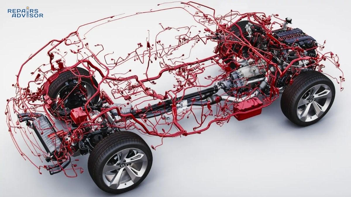
Modern vehicles contain several kilometers of electrical wiring—enough to stretch across multiple city blocks if laid end-to-end. This complex network doesn’t run loose through your vehicle; instead, it’s organized into wiring harnesses, the carefully engineered bundles that function as your car’s nervous system. Just as your body relies on nerves to transmit signals from your brain to every muscle and organ, your vehicle depends on wiring harnesses to distribute electrical power and data signals to every system, from the engine management computer to the dome light.
Understanding how wiring harnesses work isn’t just academic knowledge—it’s practical insight that helps you diagnose mysterious electrical problems, understand repair estimates, and recognize when seemingly unrelated issues actually share a common cause. When your dashboard lights flicker while your radio cuts out and your power windows slow down, you’re likely experiencing a wiring harness problem. When your check engine light illuminates alongside transmission warnings and ABS alerts, the root cause might be a damaged wire bundle rather than multiple failing systems.
The critical importance of wiring harnesses becomes clear when you consider what happens when they fail. A single corroded connector can disable your vehicle’s starting system. A wire rubbed through by vibration can cause intermittent misfires that puzzle even experienced mechanics. Rodent damage to a harness section can create a cascade of electrical failures that seem completely unrelated. In extreme cases, damaged wiring harnesses can create fire hazards—the National Fire Protection Association reports that electrical failures contribute to thousands of vehicle fires annually, with wiring harnesses frequently implicated.
Whether you’re an intermediate DIY enthusiast looking to understand electrical troubleshooting, a professional mechanic seeking comprehensive technical knowledge, or a beginner trying to make sense of your vehicle’s electrical system, this guide provides the foundation you need. We’ll explore how harnesses integrate with your vehicle’s charging system, how circuit protection prevents damage, and how modern vehicles reduce wire complexity through intelligent design.
Critical Safety Note: Working with automotive electrical systems requires disconnecting the battery and following proper safety procedures. Incorrect wiring connections can damage expensive electronics costing thousands of dollars, create fire hazards, or cause serious injury. This article provides educational information to help you understand how wiring harnesses function and when professional service is necessary. Always consult professional service for complex electrical repairs, especially on hybrid or electric vehicles with high-voltage systems that can deliver lethal shocks. The orange-colored cables in hybrid and electric vehicles carry voltages exceeding 400 volts—sufficient to cause instant death—and must only be serviced by certified technicians with specialized training and safety equipment.
Wiring Harness Components and Construction Explained
A wiring harness is far more than simply wires bundled together with tape. It’s a precisely engineered assembly consisting of carefully selected wires, connectors, terminals, and protective materials, all designed to reliably transmit electrical power and signals throughout your vehicle’s operating life. Understanding the components that make up a wiring harness reveals why quality manufacturing and proper installation are so critical to long-term reliability.
Core Component 1: Wires and Cables
The foundation of any wiring harness is the wire itself—copper multi-core flexible conductors that combine electrical conductivity with mechanical flexibility. Unlike the solid copper wire used in home electrical systems, automotive wires consist of multiple thin copper strands twisted together, typically ranging from 7 to 133 individual strands depending on the wire gauge and flexibility requirements. This multi-strand construction allows the wire to flex repeatedly without breaking, essential in an environment where constant vibration, temperature cycling, and occasional flexing occur throughout the vehicle’s life.
Wire gauge selection is critical for safety and reliability. Automotive wire gauges are measured in square millimeters in most of the world (or AWG—American Wire Gauge—in North America), with smaller numbers indicating thicker wires capable of carrying higher currents. The most common wire gauges in automotive harnesses range from 0.35mm² for low-current sensor signals up to 25mm² for high-current battery cables. Using undersized wire for a given current load creates excessive resistance, causing voltage drop that affects component performance, generates heat that degrades insulation, and in extreme cases can melt the wire and start fires.
Each wire in a harness is individually insulated with materials selected for their specific operating environment. Standard interior circuits typically use PVC (polyvinyl chloride) insulation, which provides good electrical insulation and flexibility at moderate temperatures. Engine compartment wiring requires more heat-resistant materials like cross-linked polyethylene or Teflon, which maintain their insulating properties at temperatures exceeding 200°F. The insulation color serves a critical identification function—manufacturers follow color-coding standards that indicate circuit function, making troubleshooting and repair possible without constantly referring to wiring diagrams.
Core Component 2: Connectors and Their Critical Role
Connectors are the hardware that allows harnesses to interface with electrical components and with each other, and they represent the most common failure points in automotive electrical systems. A typical connector assembly consists of a plastic housing that holds multiple terminals in precise positions, with male pins on one half mating with female sockets on the other half. The housing design ensures proper pin alignment and includes locking mechanisms that prevent accidental disconnection from vibration.
Terminal construction within connectors determines connection reliability. High-quality terminals use brass or copper-alloy contacts with gold or tin plating to resist corrosion. The terminal design creates spring tension that maintains firm contact with the mating terminal, and this contact pressure must remain adequate throughout thousands of connection/disconnection cycles and years of vibration. Poor-quality terminals lose their spring tension over time, resulting in intermittent connections that cause frustrating electrical problems.
Weatherproof connector designs incorporate multiple sealing features to prevent moisture intrusion, the primary cause of electrical corrosion. The connector housing includes rubber seals where each wire enters, and the mating surfaces include O-ring seals that compress when the connector halves lock together. Additional protection comes from grease-filled or gel-filled connector designs that completely exclude moisture. Despite these protection measures, connectors remain vulnerable to water intrusion if seals are damaged or if the connector is improperly reassembled during service.
Core Component 3: Terminals and Connection Methods
Terminals are the metal components that physically and electrically connect wires to connectors or directly to components. The three primary terminal types each suit different applications. Crimp terminals are attached to wire ends by compressing the terminal barrel around the stripped wire using specialized crimping tools—this is the most common method in automotive applications because it creates reliable connections quickly in production. Solder terminals require heating the terminal and wire together with electrical solder, creating a metallurgical bond that provides excellent electrical conductivity and mechanical strength but takes longer to create. Insulation displacement connectors (IDC) use sharp blades that cut through wire insulation to make electrical contact without stripping the wire—these are commonly used in ribbon cables and multi-wire quick connections.
Terminal quality significantly affects connection reliability. A properly crimped terminal creates both mechanical grip on the wire and intimate metal-to-metal contact for electrical conductivity. Poor crimping—too loose or too tight—results in high resistance connections that generate heat and eventually fail. Professional-grade crimping tools include ratcheting mechanisms that ensure proper compression, while cheap crimpers produce inconsistent results that lead to premature failures.
Core Component 4: Protective Covering and Bundling
Once individual wires are assembled into a harness, they require protection from the harsh automotive environment. Multiple protective materials serve different purposes depending on harness location. Electrical tape provides basic bundling and protection in benign interior environments where temperature and abrasion are minimal. Split-loom tubing and corrugated conduit protect harnesses in more demanding applications—the flexible corrugated design resists crushing while allowing the harness to bend, and the ridged exterior resists abrasion from contact with metal structures.
Heat-shrink tubing creates watertight seals around wire splices and connections by shrinking tightly when heated. Some heat-shrink tubes include internal adhesive that melts during heating, creating a completely sealed repair. Braided sleeving made from polyester or fiberglass provides abrasion resistance while maintaining flexibility, and conductive braided sleeving made from tinned copper provides electromagnetic interference (EMI) shielding for sensitive signal wires.
Wire routing and securing determine how well protective covering performs. Harnesses must be secured at appropriate intervals using clips, brackets, or cable ties to prevent excessive movement that causes wear. Where harnesses pass through sheet metal body panels, rubber grommets protect the wires from sharp metal edges. Routing must maintain adequate clearance from heat sources like exhaust manifolds, moving components like drive belts, and sharp edges that could abrade the protective covering over time. Professional harness installation follows specific routing diagrams that ensure proper clearances and secure mounting throughout the vehicle.
Harness Types by Vehicle Location
Automotive wiring harnesses are typically organized by location, with each major harness designed for its specific operating environment. The engine harness is perhaps the most demanding application, connecting the engine control unit (ECU) to dozens of sensors, actuators, and the ignition system. This harness must withstand extreme conditions—temperatures exceeding 200°F from engine heat, constant vibration from engine operation, exposure to oil and coolant that can degrade insulation, and occasional water spray from rain or car washing. Engine harnesses typically use high-temperature silicone or Teflon insulation, multiple layers of protective covering, and mounting systems that secure the harness away from the hottest engine components while maintaining necessary clearances from moving parts.
The body harness connects interior and exterior lighting, power windows, power locks, the entertainment system, and climate control components. This harness experiences moderate temperatures and minimal vibration compared to the engine harness, but must interface with numerous connectors as circuits branch to doors, lights, and control switches throughout the vehicle. Body harnesses often include the most wire branches and connectors, making them complex assemblies despite their more benign operating environment.
The instrument panel harness serves as the central electrical hub, connecting dashboard gauges, warning lights, the infotainment system, climate control, and steering column controls. This harness integrates extensively with the vehicle’s computer network, carrying both power and data signals. Modern instrument panel harnesses increasingly use multiplexed communication—sending multiple signals over shared wires—to reduce wire count and harness complexity.
The chassis or underbody harness runs the length of the vehicle, connecting frame-mounted components like ABS wheel speed sensors, the fuel pump, trailer lighting connections, and rear lighting assemblies. This harness faces harsh environmental exposure—road salt, moisture, debris impacts, and temperature extremes—requiring the most robust protective covering and weatherproof connectors of any harness in the vehicle.
Understanding these harness types helps diagnose electrical problems by location. If multiple engine-related electrical components fail simultaneously, the engine harness is the likely culprit. If your dashboard systems malfunction together, focus on the instrument panel harness. This location-based diagnostic approach narrows troubleshooting significantly compared to treating each electrical symptom as an independent problem.
Wire Gauge and Current Capacity Relationships
Selecting proper wire gauge for a given electrical load is fundamental to safe, reliable electrical system design. Wire gauge determines how much current the wire can safely carry—too small a wire for the load results in excessive resistance, voltage drop, heat generation, and potential fire hazard. The relationship between wire gauge and current capacity is straightforward: larger diameter wires (smaller gauge numbers in AWG, larger numbers in mm²) can carry more current because they offer less electrical resistance per unit length.
Common automotive wire applications use these typical specifications: 0.5mm² wire handles 5-10 amps and is used for instrument lights, indicator lights, and door courtesy lights—circuits that draw minimal current. 0.75mm² wire carries 10-15 amps and powers license plate lights, brake lights, and turn signals. 1.0mm² wire rated for 15-20 amps handles fog lights and horn circuits. 1.5mm² wire capable of 20-30 amps powers headlights and cooling fans. 2.5-4.0mm² wire handling 40-60 amps serves main power distribution circuits and high-current accessories. Finally, 10mm² and larger cable rated for 150+ amps is reserved for battery cables, starter motor circuits, and alternator output cables that must carry enormous currents during engine starting and maximum charging.
These current ratings assume proper installation—adequate wire length to minimize resistance, secure connections that prevent resistance from developing at terminals, and proper protection from heat that would degrade the insulation. When repairs require splicing into existing harness wiring, using wire gauge equal to or larger than the original wire is essential. Using smaller wire “because it’s easier to work with” creates a weak point that will eventually fail, potentially causing a fire.
The relationship between wire gauge, voltage regulation, and circuit protection demonstrates how automotive electrical systems integrate multiple components for reliability and safety. Each circuit in a wiring harness connects through the power distribution system with appropriately sized fuses or circuit breakers that protect against overcurrent conditions, while automotive relays allow low-current switches to control high-current loads safely.
How Wiring Harnesses Work: Technical Operation
Understanding how wiring harnesses function requires looking beyond the physical components to examine the electrical principles that govern power distribution, signal transmission, and circuit protection throughout your vehicle. While the copper wire and plastic connectors are visible, the invisible flow of electrons and data signals represents the actual work the harness performs.
Step 1: Power Distribution from Battery Through Main Harness
The electrical system begins at the battery, which provides 12.8 volts when fully charged and at rest. When the engine runs, the alternator maintains charging system voltage between 13.5 and 14.8 volts depending on electrical load and battery state of charge. This voltage feeds the main wiring harness through primary battery cables—typically 10mm² or larger copper conductors capable of carrying over 150 amps continuously and brief surge currents exceeding 300 amps during engine starting.
The positive battery cable connects to the main fuse box or power distribution center, often located in the engine compartment. This central junction contains the largest fuses—typically 40 to 100 amps—that protect major circuit groups. From this distribution point, smaller gauge wires branch to individual circuits throughout the vehicle, each protected by an appropriately sized fuse matched to the wire gauge and expected load. A 1.5mm² wire powering headlights, for example, connects through a 30-amp fuse—large enough to handle the headlight current plus a safety margin, but small enough to blow before the wire overheats if a short circuit occurs.
The ground system completes each circuit by providing the return path to the battery. Unlike household electrical systems that use a separate ground wire for each circuit, vehicles use the metal chassis and engine block as the primary ground conductor. Black or brown ground wires in the harness connect components to nearby chassis ground points—bolts or studs that ensure solid electrical contact with the vehicle body. The engine block connects to the chassis through heavy ground straps, and additional ground straps connect the chassis back to the battery negative terminal, completing the circuit.
This ground-through-chassis design reduces wire count significantly—imagine needing a second wire from the battery to every single electrical component—but it also creates potential problems. A single corroded or loose ground connection can affect multiple circuits, causing mysterious electrical issues that puzzle inexperienced diagnosticians. When dashboard lights dim as you press the brake pedal, or your radio resets when you activate your turn signal, poor ground connections are the likely culprit.
Step 2: Signal Transmission and Communication Networks
Not all wires in a harness carry power—many carry low-current signals that communicate information between sensors, computers, and actuators. Traditional analog signal wires transmit information by varying voltage or resistance. An oxygen sensor, for example, generates a voltage signal between 0.1 and 0.9 volts that indicates whether the air-fuel mixture is rich or lean. The engine management system reads this voltage and adjusts fuel injection accordingly. Temperature sensors use variable resistance—as temperature increases, resistance changes, and the computer measures this resistance change to determine coolant temperature, intake air temperature, or transmission fluid temperature.
Modern vehicles increasingly use digital communication networks that dramatically reduce wire count while increasing data transmission capability. The Controller Area Network (CAN bus) is the most common automotive communication protocol, using just two twisted wires to carry messages between dozens of control modules at data rates from 500 kilobits per second up to 1 megabit per second. These vehicle networks allow the engine computer, transmission controller, ABS module, body control module, and instrument cluster to share sensor data and coordinate functions using a fraction of the wires required for individual point-to-point connections.
The twisted-pair design of CAN bus wiring is critical for reliable communication. Twisting the two wires together causes any electromagnetic interference to affect both wires equally, allowing the receiving electronics to reject the noise by comparing the signals between the two wires. High-quality CAN bus implementations also use shielded twisted-pair cable for additional EMI protection, termination resistors at each end of the bus to prevent signal reflections, and precise impedance control to maintain signal integrity.
Signal wires require different protection than power wires. While power wire failures typically result in components not working, signal wire problems can cause erratic behavior, false fault codes, or unstable system operation. Shielding protects sensitive signal wires from electromagnetic interference generated by high-current circuits, ignition systems, and radio frequency emissions. Proper routing separates signal wires from potential interference sources, and specified connector types ensure secure signal connections that resist vibration and corrosion.
Step 3: Load-Specific Circuit Design and Implementation
Automotive electrical circuits fall into three categories based on current requirements, and each requires appropriate wire gauge, switching method, and protection. Understanding these categories helps diagnose problems and plan repairs correctly.
High-current circuits draw 50-300+ amps and require the heaviest wire gauges and most robust protection. The starter motor circuit exemplifies high-current design—when you turn the ignition key to start, the starter solenoid closes heavy contacts that connect the battery directly to the starter motor through 10-25mm² cables. These cables must carry 150-300 amps for several seconds during cranking, generating significant heat even in properly sized conductors. The alternator output circuit similarly uses heavy gauge wire because charging currents can reach 80-150 amps in modern vehicles with extensive electrical accessories. These circuits typically use fusible links—special sections of wire with lower melting points than the main conductors—rather than conventional fuses, because the enormous currents involved would require impractically large fuses.
Medium-current circuits serve components drawing 10-50 amps—headlights, HVAC blower motors, cooling fans, power windows, and heated seats. These circuits typically use relay control, where a small switch current activates a relay coil, and the relay contacts switch the main circuit current. This design allows lighter gauge wire from the switch to the relay, with heavy wire only between the relay, fuse box, and load. A headlight circuit, for example, uses perhaps 0.5mm² wire from the headlight switch to the relay coil, but 1.5-2.5mm² wire from the relay contacts through the fuse to the actual headlights.
Low-current circuits include interior lighting (drawing 0.5-5 amps), sensor circuits (typically milliamps), and computer module power supplies (1-5 amps). These circuits often connect directly through switches without relay control, and many are controlled directly by body control computers that switch the ground side of the circuit. Modern vehicles reduce low-current circuit wire count dramatically through multiplexing—the door module, for example, might include switches for power windows, locks, and mirror controls, but instead of running individual wires from each switch to a control module, the door module communicates switch status over the CAN bus, and the body control module activates the appropriate motors or solenoids.
Step 4: Junction Boxes and Circuit Distribution Points
Large wiring harnesses don’t run continuously from the battery to every component—instead, they incorporate junction boxes and distribution points where circuits branch and reconnect. The main fuse box serves as the primary distribution point, typically containing 30-60 individual fuses and relays organized by circuit function and location. Sub-junction boxes located in different areas of the vehicle provide secondary distribution points closer to the loads they serve. Under-hood junction boxes, instrument panel junction boxes, and rear body junction boxes allow harness sections to be disconnected for service without affecting unrelated circuits.
These distribution points also provide diagnostic access. Modern fuse boxes include test points where technicians can measure voltage with a multimeter without backprobing connectors or piercing wires. Some advanced fuse boxes incorporate “smart” features—solid-state switching that eliminates traditional relays, programmable fuse ratings that adapt to different vehicle equipment options, and diagnostic capabilities that store fault codes when overcurrent conditions occur.
Junction box location and design affect serviceability significantly. Ideally, junction boxes are positioned for easy access—under the hood with the lid easily removed, or behind easily removable dashboard panels. Poor junction box placement, such as under the dashboard requiring significant disassembly to access, or in the cowl area where water intrusion causes corrosion, creates service difficulties that increase repair costs.
Ground distribution blocks serve similar purposes on the negative side of circuits. Rather than running separate ground wires from each component all the way back to the battery, harnesses include multiple ground distribution points where several ground wires connect together and then a single heavy ground strap connects to the chassis. These ground points must be located where they make solid electrical contact with clean, unpainted metal and where they’re protected from corrosion. Ground point corrosion causes multiple mysterious electrical problems—since many circuits share a common ground point, problems with that ground affect all connected circuits simultaneously.
Step 5: Thermal Management and Temperature Protection
Wires carrying electrical current generate heat—the current flow through the wire’s electrical resistance converts some electrical energy into thermal energy. The amount of heat generated increases with the square of the current (double the current produces four times the heat) and increases linearly with resistance (thinner wires generate more heat for a given current). This heat must dissipate into the surrounding environment, or the wire temperature rises until the insulation degrades, melts, or catches fire.
Proper wire sizing ensures that normal operating currents generate minimal heat—wires warm slightly but remain well below their maximum temperature rating. Insulation materials are rated for continuous operating temperatures ranging from 80°C (176°F) for basic PVC insulation up to 200°C (392°F) for high-temperature silicone or Teflon insulation. Engine compartment harnesses use high-temperature insulation because ambient temperatures near the engine routinely reach 120-140°F, and areas near exhaust manifolds can exceed 200°F. Interior harnesses use standard temperature insulation because cabin temperatures rarely exceed 100-120°F even on hot summer days.
Heat-resistant materials become critical in specific locations. Wires routing near exhaust manifolds require Teflon insulation and protective heat shields or heat-reflective wrapping. Wires connecting to components that themselves generate heat—like ignition coils, headlight sockets, and climate control heater elements—require additional temperature margin. Undersizing wire gauge in these applications creates a cascading failure mode: excessive resistance generates heat, heat degrades insulation, degraded insulation allows short circuits, and short circuits dramatically increase current flow, generating even more heat until the wire melts or catches fire.
Adequate air circulation helps dissipate heat from wiring harnesses. Tightly bundled harnesses wrapped in non-breathable tape or conduit trap heat, increasing operating temperature. Professional harness design specifies maximum bundle diameter, requires ventilated protective covering in high-temperature areas, and maintains separation from heat sources. When repairs require adding circuits to existing harnesses, maintaining these design parameters prevents creating localized hot spots that lead to premature failures.
Step 6: Protection Systems and Fault Prevention
Multiple protection systems work together to prevent harness damage from electrical faults. Fuses and circuit breakers provide overcurrent protection—when current exceeds the fuse rating, the fuse element melts, opening the circuit before wire damage occurs. Proper fuse sizing matches the wire gauge: a 10-amp fuse protects 0.75mm² wire, a 20-amp fuse protects 1.0-1.5mm² wire, and so forth. Using oversized fuses “to stop them from blowing” defeats the protection system and allows wires to overheat, risking fire.
Diodes prevent reverse current flow in circuits where reverse polarity would damage components. Ignition coil drivers, solenoid circuits, and relay coils typically include suppression diodes that absorb voltage spikes when the coil energization suddenly stops—without these diodes, the voltage spike can reach hundreds of volts, damaging sensitive electronic components. Modern electronics also include various surge protection devices that clamp voltage spikes from lightning strikes, alternator load dumps, and other transient events.
Physical protection systems prevent mechanical damage to harnesses. Routing specifications maintain clearances from sharp edges, hot surfaces, and moving components. Secure mounting prevents harness movement that causes abrasion wear—harnesses should be secured at intervals short enough to prevent sagging or bouncing but with enough slack to accommodate normal chassis flexing and suspension movement. Grommets where harnesses pass through sheet metal provide both sealing and edge protection. Heat shields protect harnesses routing near exhaust components, and protective loom or conduit shields harnesses in areas vulnerable to road debris impact.
Connector design includes mechanical protection features: locking tabs prevent accidental disconnection from vibration, secondary locks prevent partial mating that creates intermittent connections, and keyed housings prevent incorrect connector mating. Waterproof connectors use multiple sealing levels—individual wire seals where each wire enters the connector housing, O-ring seals on the mating surfaces, and sometimes grease or gel filling that completely excludes moisture. Despite these protection measures, connectors remain the most common harness failure points because they concentrate mechanical stress and moisture intrusion risk.
Real-Time System Integration and Modern Developments
Modern wiring harness operation integrates extensively with vehicle computer systems for intelligent power management and fault detection. The engine control unit monitors sensor signals traveling through the harness to optimize combustion and control emissions. The body control module manages interior and exterior lighting, power locks, and power windows through the body harness. The instrument cluster communicates with numerous modules over the CAN bus to display engine speed, vehicle speed, fuel level, and warning indicators. The transmission control module coordinates shift quality and timing based on engine torque, vehicle speed, and driver inputs—all transmitted through harness wiring.
Advanced electrical systems include diagnostic capabilities that monitor harness function. Smart power distribution modules measure current draw on individual circuits and store fault codes when overcurrent or undercurrent conditions occur. Ground monitoring detects poor ground connections by measuring voltage drop. Sensor supply monitoring verifies that 5-volt or 12-volt sensor supply circuits maintain proper voltage. These diagnostic capabilities can identify intermittent faults that would be nearly impossible to troubleshoot otherwise—a connection that fails only when the vehicle hits bumps, or a circuit that works fine when cold but fails when hot.
Multiplexed communication networks dramatically reduce harness complexity in modern vehicles. Where a 1990s vehicle might use 10 wires to control power windows (two wires to each motor plus power and ground), a modern multiplexed system uses just four wires—CAN high, CAN low, power, and ground—serving window switches in all four doors. The door modules receive commands over the CAN bus and control the window motors locally. This architecture reduces wire count by 60% while adding functionality like one-touch operation, anti-pinch protection, and memory positions.
Looking forward, automotive Ethernet promises even greater data transmission capability for advanced driver assistance systems, infotainment systems, and eventually autonomous driving systems. These systems require bandwidth far exceeding CAN bus capability—cameras alone can generate over 100 megabytes per second of data. Automotive Ethernet provides gigabit-per-second data rates over the same twisted-pair copper wiring used for CAN bus, allowing existing harness manufacturing techniques while enabling next-generation vehicle technologies.
Wiring Harness Location, Access, and Troubleshooting Guide
Understanding where wiring harnesses are located, how to access them for inspection, and how to diagnose common problems enables effective electrical troubleshooting and helps you communicate intelligently with professional technicians when complex repairs become necessary. This practical knowledge bridges the gap between theoretical understanding and real-world electrical problem-solving.
Locating Wiring Harnesses Throughout Your Vehicle
The engine compartment contains the highest concentration of wiring harnesses because the engine, transmission, and vehicle body electrical systems all converge in this area. The main engine harness typically runs along one or both sides of the engine, secured to the fenderwell, firewall, or valve covers with plastic clips and brackets. You’ll see the harness as black corrugated tubing or cloth-wrapped bundles ranging from 1 to 3 inches in diameter, with multiple branch connections leading to sensors, actuators, and the fuse box. Heat shields—shiny metal barriers or heat-reflective wrapping—separate the harness from exhaust manifolds in high-temperature areas. Follow the harness from the main fuse box to identify how it routes around the engine and where major branch points occur.
The transmission harness connects the transmission control module to the transmission, typically entering the transmission through a connector near the transmission pan. This harness branches to solenoids, speed sensors, and pressure sensors inside the transmission. External wiring to the transmission is relatively simple, but internal transmission wiring can be complex and vulnerable to fluid contamination if seals fail.
Underbody and chassis harnesses run the length of the vehicle, typically along the driver’s side frame rail where they’re somewhat protected from road debris. Heavy-duty protective covering—usually thick corrugated conduit—shields these harnesses from rock impacts, road salt, and moisture. Branch connections lead from the main chassis harness to ABS wheel speed sensors at each wheel, the fuel pump and level sensor at the fuel tank, trailer lighting connectors, and rear lighting assemblies. Inspecting chassis harnesses requires raising the vehicle on a lift or jack stands for clear visibility.
Interior harnesses are generally the most accessible, though they require some panel removal to inspect thoroughly. Behind the dashboard, the instrument panel harness connects the instrument cluster, radio, HVAC controls, and steering column switches. Modern vehicles often incorporate this harness into a body control module that mounts to the back of the fuse panel. Door harnesses run from the body through the door hinges to door-mounted components—power window motors, lock actuators, mirror controls, and speaker connections. These harnesses flex thousands of times as doors open and close, making them vulnerable to wire breakage from flexing fatigue. Headliner harnesses connect interior lights, sunroof motors, and antenna amplifiers. Under-seat harnesses serve power seat motors, seat heaters, and airbag sensors.
Visual identification of harnesses is straightforward once you know what to look for. Protective covering distinguishes harnesses from individual wires—you’ll see corrugated conduit (flexible tubes with ridges), split-loom (slotted tubing), cloth wrapping, or spiral wrap protecting wire bundles. Large connectors with 10-40 pins mark major harness junction points. Color-coded individual wires visible where the protective covering ends help identify specific circuits. Harness routing typically follows logical paths along the vehicle structure, secured at regular intervals with clips or brackets.
Common Wiring Harness Problems and Diagnostic Approaches
Electrical problems can seem mysterious, but wiring harness issues follow predictable patterns. Understanding these common failure modes helps you diagnose problems systematically rather than replacing components randomly.
Intermittent electrical failures are among the most frustrating problems—systems that work sometimes but not others, or problems that appear and disappear without obvious cause. The root cause is usually a connection that makes contact inconsistently due to corrosion, loose terminals, or broken wire strands. Perform the “wiggle test” to diagnose: while the problem is occurring, gently move the suspect harness section while watching for the symptom to change. If moving the harness makes the problem come and go, you’ve identified the problem area. Common locations for intermittent connections include door hinges where flexing breaks wire strands, engine mounts where vibration loosens connections, and any connector exposed to moisture that develops corrosion.
When multiple unrelated circuits fail simultaneously, suspect a common connection point. If your dashboard lights, radio, and power windows all stop working at once, they likely share a common ground point that has failed. Measure voltage drop to diagnose ground problems: connect your multimeter’s positive lead to the component’s ground terminal and the negative lead to the battery negative post, then activate the circuit. You should read less than 0.1 volts; readings of 0.5 volts or higher indicate significant resistance in the ground path requiring repair.
Repeatedly blown fuses indicate a short circuit somewhere in that circuit’s wiring. The short circuit creates a low-resistance path to ground that allows excessive current flow, blowing the fuse. Never install a larger fuse “to fix” this problem—oversized fuses allow the wire to overheat and potentially catch fire. Instead, disconnect the load (the component the fuse powers) and measure resistance between the fuse socket and ground. With the load disconnected, you should read infinite resistance (overload on most digital multimeters). Any measurable resistance indicates a short circuit. Locate the short by systematically disconnecting harness sections until the resistance disappears, identifying which section contains the fault.
Corrosion and moisture damage manifest as green or white crusty buildup on connectors and terminals. Automotive connectors use various metals—copper, brass, tin, gold—that react with moisture to form oxides and other corrosion products. These corrosion layers act as insulators, increasing connection resistance and eventually preventing current flow entirely. Inspect connectors regularly, especially in areas exposed to moisture: engine compartment connectors near the radiator, chassis harness connections underneath the vehicle, and door harness connections that get wet when it rains. Clean corroded connectors with electrical contact cleaner, carefully scrub terminals with a small brass brush, and apply dielectric grease to prevent future corrosion.
Engine performance issues—misfires, rough idle, poor acceleration—sometimes result from engine harness degradation rather than sensor or component failure. Heat and vibration gradually damage engine harness insulation, especially on oxygen sensor wiring and injector connections. Inspect the engine harness for cracked insulation, especially where the harness contacts hot engine components or passes through areas with limited clearance. A simple visual inspection can reveal damaged wiring that explains multiple diagnostic trouble codes and drivability complaints.
Rodent damage has become increasingly common as manufacturers switched to soy-based wire insulation. Rodents find this insulation attractive food and will chew through multiple wires in a single harness section, causing seemingly unrelated electrical failures throughout the vehicle. Evidence includes visible teeth marks on wiring insulation, finding nesting material in the engine compartment, or discovering multiple wires with insulation chewed away. Prevention includes rodent deterrent tape with capsaicin (hot pepper extract), peppermint oil sprayed in the engine compartment, and regular inspection if you park in areas with rodent activity. Repair typically requires replacing the damaged harness section because splicing multiple wires reliably is time-consuming and expensive.
Electrical problems on hybrid and electric vehicles require special caution. Orange-colored cables indicate high-voltage circuits operating at 200-600+ volts—sufficient to cause instant death from electrical shock. Never attempt to inspect, test, or repair orange high-voltage cables. These systems include multiple safety interlocks and require certified technicians with specialized training, insulated tools, and proper protective equipment. Even experienced automotive technicians cannot safely work on high-voltage systems without specialized training.
Access Requirements and DIY Capabilities
For intermediate DIY enthusiasts, several wiring harness inspection and maintenance tasks are within your capability, while others require professional service. Understanding this boundary helps you work safely within your skill level while recognizing when professional expertise is necessary.
Basic visual harness inspection is beginner-friendly and requires no special tools. With the vehicle safely supported and the battery disconnected, systematically inspect visible harness sections for damage. Look for cracked or melted insulation indicating heat damage, abraded areas where the harness rubs against metal, loose or disconnected connectors, and corrosion on terminals. Use a flashlight to inspect areas with limited visibility—behind the engine, under the dashboard, and along the chassis. Note any damaged areas for repair or professional evaluation. This basic inspection takes 30-60 minutes and can identify problems before they cause breakdowns.
Basic connector service qualifies as intermediate-level DIY maintenance. When you find corroded connectors during inspection, disconnect the battery for safety, carefully separate the connector halves (note which orientation they mate), spray both halves with electrical contact cleaner, gently scrub the terminals with a small brass brush to remove corrosion, dry thoroughly with compressed air or allow to air-dry, apply a thin coating of dielectric grease to the terminals (prevents future corrosion without interfering with electrical contact), and reconnect the connector halves until the locking tab clicks firmly. Required supplies cost less than $20 and can prevent many electrical problems. Take photos before disconnecting complex multi-connector areas to ensure correct reassembly.
Simple wire repairs represent the advanced end of intermediate DIY capabilities. When you discover a broken wire or worn insulation, proper repair requires cutting out the damaged section, stripping 1/4 inch of insulation from both wire ends, selecting replacement wire that matches the original gauge exactly (critical for safety), overlapping the wires about 1 inch and twisting them together, soldering the joint with rosin-core electrical solder, and covering the repair with adhesive-lined heat-shrink tubing that seals moisture. The correct approach differs dramatically from the amateur “twist and tape” repair that creates unreliable high-resistance connections. Required tools include wire strippers, a soldering iron (60-100 watts for automotive work), rosin-core solder, and assorted heat-shrink tubing. If you lack these tools or soldering skills, professional repair ensures a reliable long-term fix.
Professional service becomes necessary when diagnostics exceed basic visual inspection and voltage measurement. Modern vehicles require specialized diagnostic equipment—professional-grade scan tools that read fault codes from all control modules, digital storage oscilloscopes that analyze sensor signals, and complete wiring diagrams that show exactly how circuits connect. Chasing an intermittent electrical fault without this equipment wastes time and money replacing parts that might not be at fault. Professional electrical diagnostic time typically costs $100-150 per hour, but efficiently identifies problems that could take days of guessing to find.
Complete wiring harness replacement requires professional service due to complexity and time requirements. Engine harness replacement typically requires 10-20 hours of skilled labor because the technician must disconnect hundreds of connections, carefully route the new harness following the factory routing diagram, reconnect all components correctly, and test every circuit for proper function. Total cost for engine harness replacement ranges from $1,500 to over $4,000 depending on the vehicle, with parts costs ranging from $500 to $2,000 and labor adding $1,000 to $2,500. Complete vehicle rewiring—necessary only after extreme damage like flood or fire—can cost more than the vehicle’s value.
Critical Safety Considerations
Working with automotive electrical systems requires strict safety protocols to prevent injury, vehicle damage, and fire hazards. Always disconnect the battery negative terminal before working on any wiring harness—this single step prevents accidental short circuits while you work. Wait at least 15 minutes after disconnecting the battery before working on airbag system wiring, because airbag backup capacitors can deploy airbags for several minutes after power disconnection.
Never probe wiring harnesses with sharp objects like safety pins or nails—this damages wire insulation and creates future short circuit risks. Use proper back-probing tools designed for electrical testing, or if measuring voltage at a connector, use manufacturer-specified test points or carefully backprobe with proper pin adapters. Damaged wire insulation from improper probing is a common source of subsequent electrical problems.
Use proper connectors and terminals for all repairs—never rely on twisted wires wrapped with electrical tape. This amateur repair method creates high-resistance connections that generate heat and fail unpredictably. Heat-shrink tubing with internal adhesive or quality crimp connectors with proper crimping tools create reliable repairs that last. Maintain original wire gauge when splicing or adding circuits—using lighter wire “because it’s easier to work with” creates fire hazards.
Secure all repaired wiring away from heat sources, sharp edges, and moving components. Wire routing determines long-term reliability—poorly routed repairs will fail from heat exposure or abrasion even if the splice itself was performed correctly. Use appropriate protective covering—split loom for moderate protection, corrugated conduit for harsh environments, and heat-resistant materials near exhaust components.
If you smell burning plastic or electrical odors, immediately disconnect the battery to prevent fire. Electrical fires can progress rapidly once started, and many occur in hidden areas where small fires grow undetected before breaking through into visible areas. If you see melted wire insulation anywhere in the harness, treat this as an emergency requiring immediate professional diagnosis—multiple factors can cause wire overheating, and identifying the root cause prevents fire hazards.
Professional diagnosis and repair are essential when you face persistent electrical problems that resist simple fixes, when multiple systems fail with no obvious cause, when you lack proper diagnostic equipment to identify the problem, when repairs require harness replacement, or when safety systems like anti-lock brakes, airbags, or stability control are affected. These systems are too important to risk with amateur repairs. Additionally, factory-specific repair procedures and special tools often apply to modern vehicles—attempting repairs without this information and equipment can damage expensive electronics or create safety hazards.
For comprehensive wiring diagrams and vehicle-specific repair procedures, consult professional service manuals. Manufacturers like Ford, Toyota, Honda, and Chevrolet publish detailed service information that includes complete wiring diagrams, connector pin-outs, and diagnostic procedures specific to each model year.
Understanding Wiring Harness Function Enables Better Vehicle Ownership
Wiring harnesses represent the circulatory and nervous systems of modern vehicles combined—distributing electrical power to every component while simultaneously carrying the data signals that coordinate vehicle operation. The thousands of individual connections in these complex assemblies work reliably for years under harsh conditions when properly manufactured, installed, and maintained. Understanding how harnesses function, how they’re constructed, and how they fail helps you maintain your vehicle’s electrical reliability and recognize when professional service becomes necessary.
The key insights from this comprehensive exploration clarify several critical points. First, proper wire gauge selection and circuit protection prevent the most serious harness failures—fires and complete electrical system failure. Using correct gauge wire for each application and protecting circuits with appropriately sized fuses creates safe, reliable electrical systems. Second, connectors and terminals represent the most common failure points, requiring regular inspection and maintenance to prevent corrosion and loose connections. Third, harness routing and physical protection determine long-term reliability as much as the electrical design—poorly routed harnesses fail from heat or abrasion even when electrically sound. Fourth, modern multiplexed communication networks dramatically reduce wire count while enabling sophisticated vehicle features. Fifth, diagnostic capability built into modern electrical systems helps identify intermittent faults that would be nearly impossible to troubleshoot otherwise.
For intermediate DIY enthusiasts, wiring harness knowledge enables effective troubleshooting of many electrical problems. Visual inspection identifies obvious damage. Voltage and resistance measurements with a digital multimeter diagnose power supply and ground problems. Systematic diagnosis by circuit location and function narrows possible causes efficiently. Understanding which repairs are within DIY capability and which require professional expertise prevents time-wasting guesswork and ensures safe, reliable repairs.
For professional mechanics, comprehensive harness understanding improves diagnostic efficiency and repair quality. Recognizing common failure patterns by vehicle age, model, and operating conditions speeds diagnosis. Proper repair techniques—using correct wire gauge, quality terminals and connectors, appropriate protective covering, and proper routing—ensure long-term reliability. Knowledge of modern communication networks and diagnostic capabilities allows efficient use of professional scan tools and diagnostic equipment.
For complete beginners, understanding basic harness function demystifies vehicle electrical systems. You learn which problems you can diagnose yourself and which require professional expertise. You understand why proper repairs cost what they do—harness replacement requires hours of skilled labor due to the complexity involved. You recognize warning signs of serious electrical problems that require immediate attention.
When Professional Consultation Is Essential: While basic harness inspection and connector maintenance fall within intermediate DIY capabilities, complex electrical diagnostics require professional equipment and expertise. Modern vehicles integrate dozens of computer systems through wiring harnesses, and incorrect repairs can damage control modules costing thousands of dollars to replace. If you experience persistent electrical problems that resist simple fixes, multiple circuit failures with no obvious cause, or any issues affecting safety systems—anti-lock brakes, airbags, stability control—professional diagnosis is essential. For hybrid and electric vehicles, all high-voltage system work MUST be performed by certified technicians due to lethal electrical shock hazards. The orange-colored cables in these vehicles carry voltages exceeding 400 volts that can kill instantly.
The investment in professional electrical service prevents much more expensive secondary damage. A $200 diagnostic service that identifies a corroded ground point saves you from replacing hundreds or thousands of dollars in control modules damaged by voltage spikes. A $1,500 engine harness replacement performed correctly with OEM parts lasts the vehicle’s remaining life, while amateur repairs with incorrect materials fail repeatedly and risk fire hazards. Professional technicians have access to vehicle-specific wiring diagrams, diagnostic procedures, and repair techniques not available to general repair information—this specialized knowledge ensures first-time-correct repairs.
Regular maintenance prevents many wiring harness problems. Annual inspection of visible harness sections identifies damage before it causes failures. Keeping connectors clean and protected with dielectric grease prevents corrosion. Ensuring proper harness routing with adequate clearances and secure mounting prevents abrasion and heat damage. These simple preventive measures cost almost nothing but dramatically extend electrical system reliability.
Need detailed wiring diagrams and diagnostic procedures specific to your vehicle? Professional repair manuals provide complete electrical schematics, connector pinouts, circuit descriptions, diagnostic flowcharts, and repair procedures that take you step-by-step through electrical system service. These manufacturer-sourced resources ensure you have accurate information for your specific vehicle year, model, and equipment rather than generic information that might not apply. Whether you’re a DIY enthusiast troubleshooting electrical issues or a professional mechanic performing complex repairs, access to comprehensive technical documentation ensures efficient, accurate electrical system service.