A variable geometry turbocharger (VGT) represents one of the most sophisticated approaches to managing exhaust energy recovery and boost control in modern engines. Unlike traditional turbochargers with fixed geometry, VGT technology uses adjustable vanes or nozzles to optimize exhaust flow across the entire engine operating range. This advanced boost control system eliminates the traditional compromise between low-end torque response and high-speed power delivery, making it particularly valuable in diesel fuel systems and high-performance applications.
For Intermediate DIY Enthusiasts: Understanding variable geometry turbocharger operation helps you recognize the complexity behind modern boost systems and appreciate why professional diagnostics are often necessary for VGT-related issues. This knowledge builds confidence in discussing forced induction systems while establishing clear boundaries for safe DIY involvement.
For Professional Mechanics: VGT systems require specialized diagnostic tools and calibration procedures. Mastering VGT technology positions you as an expert in advanced engine management, particularly valuable as more vehicles incorporate variable geometry technology across gasoline and diesel platforms.
Safety Note: Variable geometry turbocharger systems operate under extreme temperatures (up to 1000°C) and pressures. Any service work involving VGT components requires proper safety equipment and should follow manufacturer-specific procedures. Information provided here is for educational reference only.
Variable Geometry Turbocharger Parts and Construction Explained
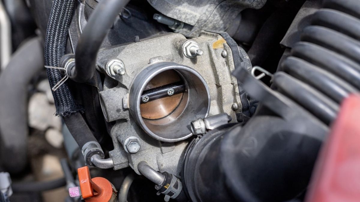
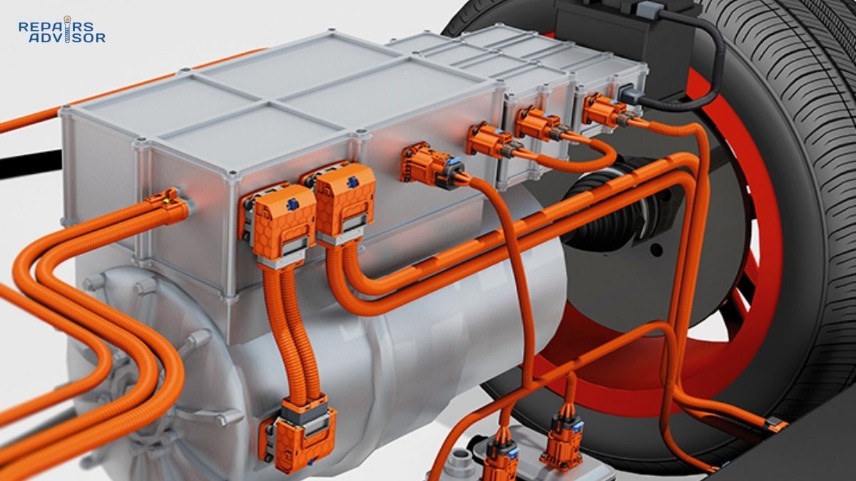
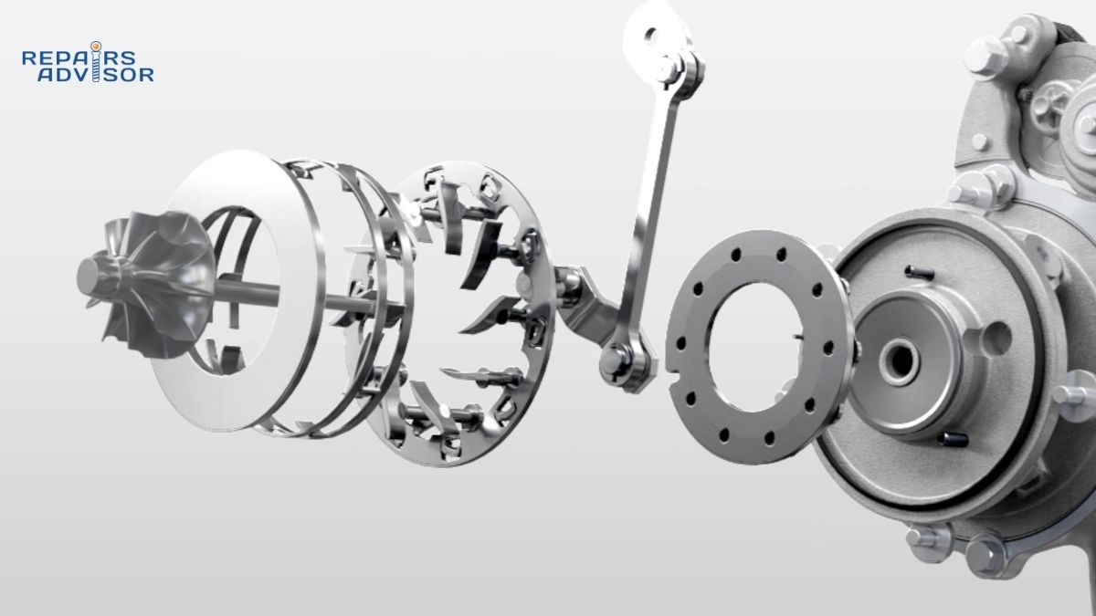
The variable geometry turbocharger builds upon traditional turbocharger architecture with sophisticated variable flow control mechanisms. The core assembly includes a precision-manufactured turbine housing containing adjustable guide vanes or a sliding nozzle ring, controlled by either pneumatic or electric actuator systems.
Primary VGT Components:
Variable Nozzle Assembly forms the heart of VGT technology, featuring adjustable vanes that pivot around individual axes or a sliding nozzle ring that changes the effective exhaust passage area. These components are manufactured from heat-resistant superalloys designed to withstand continuous thermal cycling while maintaining precise dimensional control.
Actuator Systems provide the control mechanism for geometry adjustment, with pneumatic actuators using engine vacuum or boost pressure for control, while electric actuators offer more precise positioning through ECU control integration. Modern electric VGT actuators incorporate position feedback sensors for closed-loop control.
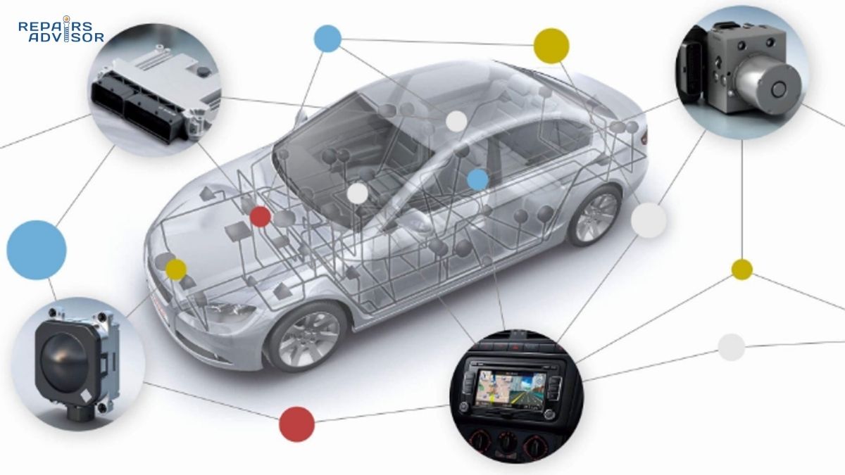
Control Electronics integrate VGT operation with overall engine management, monitoring parameters including exhaust gas temperature, boost pressure, engine load, and RPM to calculate optimal vane positioning. The control system coordinates VGT operation with other boost control components and emission control systems.
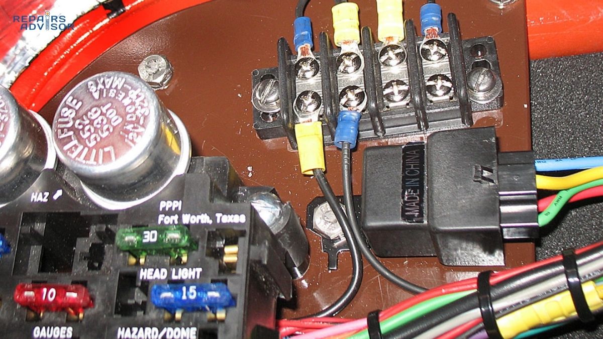
Supporting Hardware includes reinforced bearings designed for variable loading conditions, enhanced oil sealing systems to handle the complex pressure differentials created by variable geometry operation, and robust mounting systems that accommodate the additional stresses from actuator forces.
How Variable Geometry Turbocharger Works: Step-by-Step Operation
Variable geometry turbocharger operation involves continuously adjusting exhaust flow characteristics to optimize boost response across all engine operating conditions. The system represents a significant advancement over traditional wastegate-controlled turbochargers by eliminating the need to dump exhaust energy.
Step 1: Low RPM Boost Response Enhancement During low engine speeds and light loads, the VGT system positions the adjustable vanes to create a smaller effective exhaust passage area. This increases exhaust gas velocity across the turbine wheel, improving boost response and low-end torque delivery. The concentrated exhaust flow creates higher turbine wheel speeds even with relatively low exhaust energy, eliminating traditional turbo lag.
Step 2: Progressive Geometry Adjustment As engine RPM and load increase, the engine management system continuously adjusts vane positioning based on real-time operating parameters. The vanes progressively open to accommodate increasing exhaust flow while maintaining optimal turbine efficiency. This dynamic adjustment ensures peak boost pressure is maintained without over-boosting.
Step 3: High RPM Flow Optimization At high engine speeds, the VGT vanes open to their maximum position, creating the largest possible exhaust passage area. This configuration minimizes exhaust backpressure while allowing maximum exhaust flow through the turbine, optimizing high-speed power output and preventing turbocharger overspeed conditions.
Control Integration: The VGT control system coordinates with other engine systems including EGR operation, fuel injection timing, and emission control systems. In diesel applications, VGT operation significantly impacts diesel particulate filter regeneration and SCR system efficiency.
Fail-Safe Operation: When VGT actuator malfunctions occur, most systems default to a predetermined safe position, typically partially open to prevent engine damage. This fail-safe mode maintains basic turbocharger function while limiting performance to ensure continued operation.
Variable Geometry Turbocharger Location and Access Guide
Variable geometry turbochargers are typically mounted directly to the exhaust manifold or integrated exhaust housing, with the VGT actuator mechanism clearly visible on the turbine housing exterior. The actuator unit, whether pneumatic or electric, provides the most recognizable identifying feature distinguishing VGT units from conventional turbochargers.
Visual Identification Features: VGT turbochargers are identifiable by the prominent actuator mechanism mounted to the turbine housing, connected control wiring harnesses or vacuum lines, and position feedback sensors integrated into the actuator assembly. Electric VGT actuators typically feature multi-pin electrical connectors, while pneumatic units show characteristic vacuum line connections and control solenoid integration.
Access Requirements: VGT system access generally requires removal of engine covers, air filter housing components, and associated ducting to reach electrical connections and diagnostic ports. The turbocharger location varies significantly between vehicle platforms, with some requiring substantial component removal for actuator access.
Diagnostic Considerations: VGT diagnostics require specialized scan tools capable of commanding actuator positioning and monitoring real-time vane position feedback. Professional diagnostic equipment can perform VGT calibration procedures and adaptation resets following component replacement.
Professional Service Recommendations: VGT systems require specialized diagnostic equipment and calibration procedures typically beyond DIY capabilities. The precision nature of VGT control and integration with complex emission systems makes professional service strongly recommended for any VGT-related repairs or maintenance.
Heat Management Warning: VGT components operate at extreme temperatures and remain dangerously hot long after engine shutdown. Any inspection or service work must account for thermal hazards and allow adequate cooling time before handling components.
About This Information: This technical guide provides educational information about variable geometry turbocharger systems and is intended for reference purposes only. Repairs Advisor does not provide direct repair services but offers comprehensive technical documentation to support your automotive knowledge and repair planning needs.