Valve seats and guides form the foundation of precise engine breathing control, working together to ensure perfect valve sealing while managing millions of operating cycles. These critical components control gas flow timing, maintain combustion chamber integrity, and enable optimal engine performance across all operating conditions. Understanding their construction and function is essential for anyone working on engine valve systems, from weekend DIY enthusiasts to professional technicians.
Safety Notice: Valve seat and guide work requires specialized tools and precision measurements. Improper installation can cause catastrophic engine damage. Beginners should focus on inspection and cleaning procedures only. Intermediate users can handle basic valve adjustments with proper tools. Professional-level machining and installation should always be performed by qualified technicians.
Why Valve Seats and Guides Are Critical for Engine Performance
The valve seat and guide system creates the precise interface between stationary cylinder head components and moving valves. Valve seats form the sealing surface where intake and exhaust valves close against the combustion chamber, while valve guides provide accurate positioning and thermal management for valve stems during operation.
Combustion Sealing Excellence
Valve seats must create a perfect seal against valve faces to maintain compression ratio and prevent combustion gas leakage. Even microscopic irregularities can cause compression loss, rough idle, and power reduction. The sealing interface operates under extreme conditions – combustion pressures reaching 1,000+ PSI and temperatures exceeding 2,000°F on exhaust valves.
Professional mechanics recognize that valve seat concentricity directly impacts engine performance. A seat that’s off by even 0.002 inches can reduce sealing effectiveness by 30% or more. This precision requirement makes proper machining and installation crucial for reliable operation.
Heat Transfer and Thermal Management
Valve guides serve as primary heat conductors, transferring thermal energy from valve stems into the cylinder head’s cooling system. Exhaust valves depend on this heat transfer pathway to prevent overheating and premature failure. Worn guides reduce thermal conductivity and allow excessive valve temperatures.
The thermal management function becomes critical in high-performance applications. Racing engines and turbocharged powerplants generate significantly more heat, making guide-to-stem clearances and material selection crucial factors. Proper clearances ensure adequate heat transfer while maintaining precision valve motion.
Valve Motion Precision
Accurate valve positioning depends on guide bore straightness and surface finish. Guides control valve stem movement in all directions except the primary opening/closing motion. Any lateral play or binding affects valve timing, sealing, and longevity.
Modern engines with variable valve timing systems demand exceptional guide precision. Timing variations caused by worn guides can disrupt the carefully calibrated relationship between camshaft operation and valve movement, reducing performance and efficiency.
Valve Seats and Guides Parts and Construction Explained
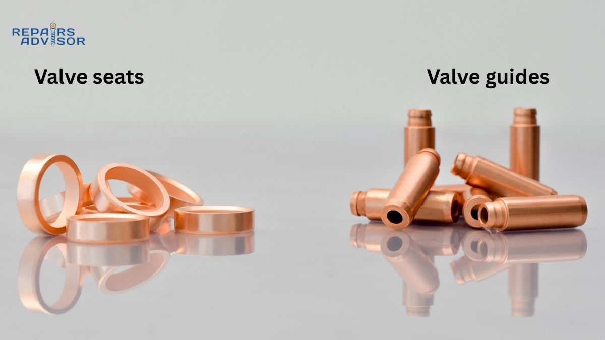
Valve Seat Design and Materials
Integral Seats: Many older and lower-stress applications use seats machined directly into the cylinder head casting. These provide excellent heat transfer but limit material choices to the base head material – typically cast iron or aluminum.
Seat Inserts: Modern engines predominantly use separate seat inserts pressed into machined recesses. This design allows optimized materials for different applications:
- Hardened steel inserts: Standard for most gasoline engines, offering good durability and machinability
- Stellite inserts: Cobalt-chromium alloy for extreme-duty applications, providing superior wear resistance
- Powder metal inserts: Advanced materials with controlled porosity and composition for specific thermal properties
Seat Angles and Geometry: Traditional seats use a single 45-degree angle, but modern designs employ multiple angles to optimize sealing and flow:
- Primary seat angle: Usually 45 degrees, creates the main sealing contact
- Top angle: Typically 30 degrees, improves airflow characteristics
- Throat angle: Often 60 degrees, enhances turbulence and mixing
Professional engine builders understand that seat width critically affects sealing and longevity. Narrower seats create higher contact pressures for better initial sealing but may wear faster. Wider seats distribute loads better but require more precise machining.
Valve Guide Construction
Integral Guides: Cast or machined directly in the cylinder head, common in older designs and some modern applications. These provide maximum strength but limit material optimization and replacement options.
Pressed-in Guides: Separate components installed in machined bores, allowing material selection for specific applications:
- Cast iron guides: Traditional material offering good wear characteristics and thermal stability
- Bronze guides: Superior thermal conductivity and natural lubrication properties
- Steel guides: High strength for demanding applications
- Specialized alloys: Materials like K-Monel for extreme conditions
Guide Dimensions and Tolerances: Critical specifications include:
- Inside diameter: Controls stem clearance, typically 0.001-0.003″ for intake, 0.002-0.004″ for exhaust
- Outside diameter: Determines interference fit in head, usually 0.002-0.004″ interference
- Length: Affects guidance stability and heat transfer capability
Valve Stem Seals Integration
Valve stem seals work with guides to control oil consumption while allowing necessary lubrication. Modern designs include:
- Umbrella seals: Simple deflector design for low-stress applications
- Positive seals: O-ring or lip-type seals for precise oil control
- PTFE seals: Low-friction materials for high-RPM applications
The seal-to-guide interface requires precise machining. Guide tops must be finished to specific dimensions and surface roughness for proper seal retention and function.
How Valve Seats and Guides Work: Step-by-Step Operation
Valve Closing Sequence and Sealing
Initial Contact: As the valve approaches its seat during the closing phase of camshaft operation, the valve face begins contact with the seat. This initial contact occurs over a precisely machined interface designed to create immediate sealing.
Load Distribution: Valve spring force, transmitted through the valve stem and guided by the valve guide, creates contact pressure between valve face and seat. This pressure must be sufficient to maintain sealing against combustion pressures while avoiding excessive stress that could cause premature wear.
Thermal Expansion Compensation: During operation, differential thermal expansion between valve, seat, and guide materials affects contact pressures and clearances. The system design accommodates these changes through controlled clearances and material selection.
Professional technicians monitor seat contact patterns using machinist’s blue or specialized marking compounds. Proper contact patterns should be centered on both valve face and seat, with uniform width around the entire circumference.
Heat Transfer Mechanisms
Conduction Through Valve Stem: Approximately 75% of exhaust valve heat transfers through the stem to the guide, with heat flux rates reaching 50-100 BTU/hr/°F depending on guide material. Cast iron guides transfer heat at roughly 25 BTU/hr/ft/°F, while bronze guides achieve 200+ BTU/hr/ft/°F, explaining their preference in high-performance applications. This pathway’s effectiveness depends on stem-to-guide clearances and guide thermal conductivity.
Seat Interface Cooling: The remaining 25% of valve heat transfers through the valve face to the seat during the closed portion of each cycle. This heat transfer occurs only when the valve is seated, making the seat contact duration critical for thermal management.
Cooling System Integration: Heat transferred to guides and seats must be effectively removed by the engine’s cooling system. Blocked coolant passages or inadequate coolant flow can cause valve burning and premature failure.
Guide Lubrication and Wear Management
Oil Film Maintenance: Valve guides require thin oil films for lubrication while minimizing oil consumption. The stem-to-guide clearance creates a controlled leakage path that provides lubrication while valve stem seals control excess oil flow.
Wear Pattern Development: Normal wear creates slight tapering in guides, with maximum wear occurring at the ends where stem side loads are highest. Monitoring wear patterns helps predict maintenance needs and identify system problems.
Contamination Effects: Combustion byproducts, particularly carbon and acids, can affect guide lubrication. These contaminants alter oil properties and can accelerate wear if not managed through proper oil filtration and change intervals.
Valve Seats and Guides Location and Access Guide
Cylinder Head Integration
Valve seats and guides integrate directly into the cylinder head casting, positioning them at the interface between combustion chambers and port passages. Understanding their location relationship helps with inspection and service procedures.
Intake Side Access: Intake valve seats and guides are typically more accessible due to their positioning on the intake port side of the head. This location often allows easier inspection without complete disassembly, though proper evaluation still requires valve removal.
Exhaust Side Considerations: Exhaust valve components operate in higher-temperature environments and may show more thermal stress effects. Their location near exhaust ports can complicate access but provides important diagnostic information about combustion conditions.
Service Access Requirements
Valve Removal Prerequisites: Accessing seats and guides for service requires complete valve removal, including:
- Valve spring compression and removal
- Valve keeper/retainer removal
- Valve stem seal replacement
- Valve extraction from guide
Specialized Tool Requirements:
- Beginner Level: Basic measurement tools for clearance checking, bore gauges for wear assessment
- Intermediate Level: Valve spring compressors, seal installation tools, precision measuring equipment
- Professional Level: Seat cutting equipment, guide installation/removal tools, surfacing machines
Workspace Preparation: Guide and seat work requires clean environments to prevent contamination. Metal particles from machining operations can cause severe damage if allowed to enter oil passages or combustion chambers.
Safety and Skill Level Guidelines
Beginner-Safe Procedures:
- Visual inspection of accessible components
- Basic clearance measurements with appropriate tools
- Cleaning of external surfaces
- Safety Limit: Never attempt seat or guide removal/installation
Intermediate Capabilities:
- Valve removal and installation
- Basic seat and guide condition assessment
- Valve stem seal replacement
- Clearance verification procedures
- Safety Limit: Leave precision machining to professionals
Professional Requirements:
- Seat cutting and refinishing
- Guide installation and reaming
- Precision measurement and tolerance verification
- Heat treatment and stress relief procedures
Diagnostic Access Points
Compression Testing Integration: Valve seat sealing problems directly affect compression test results. Systematic testing can isolate seat-related issues from other compression loss sources like piston rings or head gaskets.
Leak-Down Test Applications: Cylinder leak-down testing provides specific information about valve sealing effectiveness. Testing procedures can distinguish between intake and exhaust valve problems, guiding repair priorities.
Visual Inspection Opportunities: Borescope examination through spark plug holes can reveal seat condition and valve operation problems. This non-invasive diagnostic method helps determine repair scope before disassembly.
Essential Maintenance and Safety Information
Professional Consultation Recommended: Valve seat and guide service requires specialized equipment and precision machining capabilities. While basic inspection and cleaning can be performed by intermediate-level mechanics, installation and machining should be handled by qualified machine shops or professional technicians.
Skill-Level Safety Guidelines:
- Beginner: Focus on understanding component function and basic inspection techniques
- Intermediate: Handle valve removal/installation with proper tools and safety precautions
- Professional: Perform precision machining and installation procedures with appropriate equipment
Critical Safety Reminders: Always follow manufacturer torque specifications for valve train components. Improper installation can cause valve interference with pistons, potentially causing catastrophic engine damage. When in doubt, consult professional technicians or refer to manufacturer service manuals.
Related System Integration: Valve seat and guide condition affects engine timing systems, fuel injection efficiency, and emission control system operation. Comprehensive engine performance requires attention to all related systems.
Additional Resources: For specific vehicle applications and detailed service procedures, refer to manufacturer repair manuals available through Repairs Advisor’s comprehensive manual library. For technical support with manual selection or download issues, visit our Help Center or contact our support team at [email protected].
Information provided for reference only. Always consult manufacturer specifications and professional guidance for specific repair procedures. Repairs Advisor provides technical manuals and information – not direct repair service