Modern turbocharged engines deliver exceptional power density while maintaining fuel efficiency, making turbochargers one of the most significant advancements in engine technology. From high-performance sports cars to everyday commuter vehicles, turbocharger systems have revolutionized how engines breathe and perform. Understanding turbocharger operation helps DIY enthusiasts make informed maintenance decisions and recognize performance issues before they become expensive repairs.
Safety Note for Beginners: Turbocharger systems operate under extreme temperatures (up to 1800°F) and high pressures. Always allow proper cool-down time before working on turbo components and use appropriate safety equipment when inspecting these systems.
Why Turbochargers Are Critical for Engine Performance
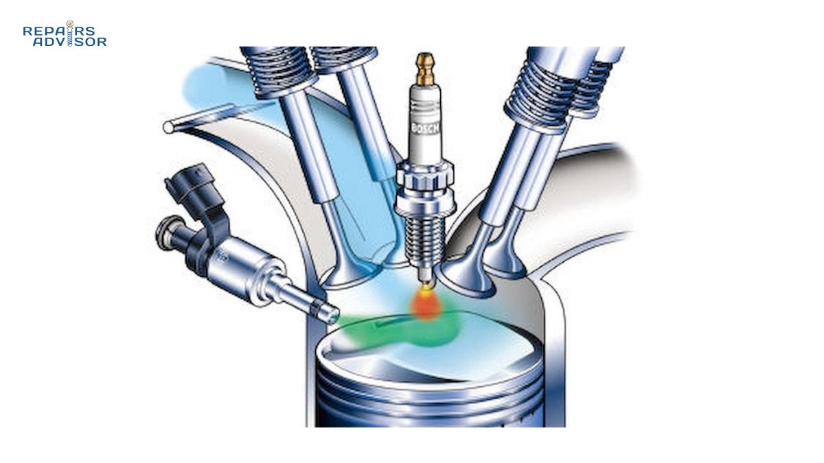
Turbochargers fundamentally change how engines generate power by forcing more air into the combustion chambers than naturally aspirated engines can achieve. This forced induction principle allows smaller displacement engines to produce power equivalent to much larger engines while consuming less fuel during normal driving conditions.
The turbocharger solves the fundamental limitation of natural engine breathing. At atmospheric pressure, engines can only draw in a limited amount of air based on their displacement and valve timing. By pressurizing the intake air to 15-20 PSI above atmospheric pressure, turbochargers can effectively double or triple an engine’s air intake capacity, enabling proportionally more fuel to be burned and dramatically increasing power output.
Modern turbocharger technology extends beyond simple power enhancement. Variable geometry turbochargers optimize boost response across the entire RPM range, while sophisticated engine management systems precisely control boost pressure to prevent engine damage and maximize efficiency.
For intermediate DIY enthusiasts, understanding turbocharger principles enables better maintenance timing decisions and helps identify early warning signs of turbo failure. Professional mechanics rely on turbocharger knowledge to diagnose complex drivability issues and recommend appropriate repair strategies for different performance goals.
Turbocharger Parts and Construction Explained
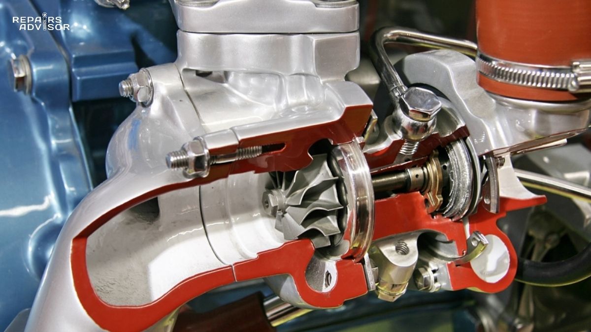
The turbocharger consists of two main assemblies connected by a common shaft: the turbine housing (hot side) and compressor housing (cold side). This simple concept masks sophisticated engineering designed to withstand extreme operating conditions while maintaining precise tolerances.
Turbine Wheel and Housing: The turbine wheel, typically made from high-temperature Inconel alloy, features precisely angled blades that extract energy from exhaust gas flow. The turbine housing channels exhaust gases through a volute design that maintains optimal gas velocity and pressure across the turbine wheel. Advanced exhaust manifold designs work in conjunction with turbine housings to maximize exhaust energy recovery.
Compressor Wheel and Housing: The compressor wheel draws ambient air through the air filter and pressurizes it before delivery to the intake manifold. The compressor housing’s diffuser section converts the high-velocity air from the compressor wheel into high-pressure, lower-velocity air suitable for engine consumption.
Center Housing and Bearing System: The center housing contains the sophisticated bearing system that allows the shaft to rotate at speeds exceeding 200,000 RPM. Most turbochargers use floating journal bearings lubricated by engine oil, though some high-performance applications employ ball bearing cartridges for reduced friction and improved response. The bearing system requires constant oil flow and pressure, making proper engine oil pump function critical for turbocharger longevity.
Wastegate System: Internal or external wastegates control boost pressure by diverting exhaust gases around the turbine wheel when target boost pressure is reached. The wastegate actuator responds to intake manifold pressure, opening the wastegate valve to prevent overboosting. Electronic boost controllers can modify wastegate operation for performance tuning applications.
Oil and Coolant Lines: Turbochargers require dedicated oil supply and return lines, with many modern applications also incorporating coolant lines for additional cooling. The oil supply line typically connects to the main oil gallery, while the return line must drain freely to the oil pan to prevent bearing damage from oil starvation or coking.
How Turbochargers Work: Step-by-Step Operation
Turbocharger operation begins with exhaust gas energy extraction and culminates in pressurized air delivery to increase engine power output. This process occurs continuously whenever the engine is running, with boost levels varying based on load conditions and throttle position.
Phase 1: Exhaust Energy Capture: Hot exhaust gases exit the combustion chambers and flow through the exhaust manifold into the turbine housing. The gases strike the turbine wheel blades at high velocity, causing the wheel to rotate. Exhaust gas temperature and flow rate directly determine available energy for turbocharger operation, which is why turbo lag occurs at low RPM when exhaust energy is minimal.
Phase 2: Shaft Power Transfer: The rotating turbine wheel drives the common shaft, which simultaneously rotates the compressor wheel on the opposite end. The shaft operates at extremely high speeds – typically 80,000 to 200,000+ RPM depending on turbocharger size and boost requirements. This speed differential from the engine (which operates at 800-7000 RPM) requires the sophisticated bearing system to maintain smooth operation.
Phase 3: Air Compression and Delivery: The compressor wheel draws ambient air through the air filter and accelerates it outward through the compressor housing. This process compresses the air to boost pressures typically ranging from 8-25 PSI above atmospheric pressure. The compressed air temperature increases significantly during compression, which is why intercoolers are essential for optimal performance.
Phase 4: Boost Control Integration: The engine management system continuously monitors boost pressure through MAP sensors and controls the wastegate operation to maintain target boost levels. During light load conditions, the wastegate may remain partially open to prevent excess boost, while under full acceleration, the wastegate closes to maximize boost pressure within safe engine limits.
Phase 5: Thermal Management: Throughout operation, the turbocharger generates significant heat from both exhaust gas exposure and air compression. The oil circulation system carries heat away from the bearings and center housing, while coolant lines (when present) provide additional cooling. This is why engine oil coolers become particularly important in turbocharged applications.
Turbocharger Location and Access Guide
Turbocharger placement varies significantly between vehicle manufacturers and engine configurations, affecting both performance characteristics and maintenance accessibility. Understanding typical turbocharger mounting locations helps with inspection routines and repair planning.
Engine Bay Positioning: Most turbochargers mount directly to the exhaust manifold or integrated turbo manifold, positioning them close to the engine block for efficient oil and coolant line routing. Front-wheel-drive vehicles often place turbochargers toward the rear of the engine bay, while rear-wheel-drive configurations may position them higher and more centrally located.
Access Considerations for Maintenance: Turbocharger oil line access typically requires removal of engine covers, air intake components, and sometimes intercooler piping. The oil supply line usually connects near the top of the turbo center housing, while the oil return line connects to the bottom and must maintain a clear drainage path to the oil pan. When planning maintenance, account for heat shield removal and potential interference with other engine accessories.
Inspection Points: Visual turbocharger inspection should focus on oil line connections for leaks, wastegate actuator movement, and compressor housing/intercooler piping for oil contamination that indicates bearing wear. The exhaust side inspection requires checking for cracked turbine housings and proper heat shield installation. Always perform these inspections with the engine cold to avoid burns from hot surfaces.
Performance Monitoring Access: Boost pressure monitoring requires access to the intake manifold pressure sensor and intercooler piping connections. Many turbocharged vehicles include boost gauge connections in the engine bay for performance monitoring. Professional diagnostic equipment connects to the engine management system through the OBD port for comprehensive turbocharger system analysis.
Brand-Specific Considerations: Different manufacturers employ varying turbocharger mounting strategies. Ford EcoBoost engines often integrate the turbocharger with the exhaust manifold assembly, while BMW frequently uses twin-scroll turbos with complex piping layouts. Toyota and Honda turbocharged engines typically prioritize serviceability with more accessible mounting locations.
Understanding turbocharger operation empowers vehicle owners to maintain these sophisticated systems properly and recognize early warning signs of potential issues. Regular maintenance of the lubrication system, timely oil filter changes, and proper warm-up/cool-down procedures significantly extend turbocharger life and maintain optimal performance.
Professional Consultation Note: While turbocharger inspection and basic maintenance can be performed by intermediate DIY enthusiasts, internal turbo repairs, wastegate adjustments, and boost pressure modifications should be handled by qualified technicians with appropriate diagnostic equipment and safety training.
Information provided for reference only. Always consult manufacturer specifications and professional guidance for specific repair procedures. Repairs Advisor provides repair manuals and technical information – we do not offer direct repair services.