If you’ve ever wondered how your truck or SUV seamlessly switches between two-wheel drive and four-wheel drive, or how all-wheel drive vehicles maintain traction in slippery conditions, the answer lies in a component most drivers never see: the transfer case. This unsung hero of the drivetrain serves as the “brain” of your vehicle’s 4WD or AWD system, intelligently distributing engine power between the front and rear axles to maximize traction, capability, and control.
Understanding how transfer cases work isn’t just for gearheads and off-road enthusiasts. Whether you’re navigating snowy highways, towing a trailer, or exploring backcountry trails, your transfer case is constantly working to keep you moving safely. This guide will walk you through everything you need to know about transfer case operation, from the basic principles that govern power distribution to the internal components that make it all possible, plus practical maintenance advice to keep your system running smoothly for years to come.
We’ll explore the key differences between part-time and full-time systems, examine why chain-driven cases dominate modern vehicles while gear-driven designs remain the choice for extreme applications, and help you recognize the warning signs that indicate your transfer case needs attention. By the end, you’ll have a solid grasp of this critical drivetrain component and the confidence to make informed decisions about maintenance and repairs. Let’s start by understanding what a transfer case actually does and why it’s essential for multi-axle drive systems.
What is a Transfer Case?
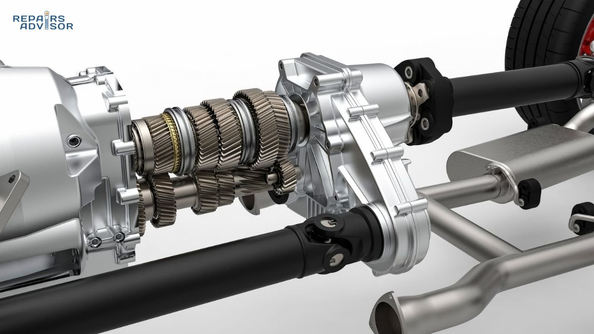
A transfer case is an intermediate gearbox that sits between your vehicle’s transmission and the drive axles, functioning as the central distribution point for engine power in four-wheel drive and all-wheel drive vehicles. Think of it as a mechanical traffic controller that decides how much power each axle receives and when. Unlike two-wheel drive vehicles that send power to either the front or rear axle alone, 4WD and AWD systems require this additional component to split torque between both ends of the vehicle, enabling superior traction and off-road capability.
The transfer case receives rotational power from the transmission’s output shaft and redirects it through two separate pathways: one leading to the front differential and another to the rear differential. This power split can be fixed at a 50/50 ratio, variable based on traction needs, or even completely disconnected from one axle depending on the system design. The transfer case accomplishes this through an internal arrangement of gears, chains, shafts, and in some designs, a center differential that allows the front and rear wheels to rotate at slightly different speeds—a necessity when turning corners or driving on varying surfaces.
Beyond simple power distribution, the transfer case performs several critical functions that enhance vehicle capability. It provides gear reduction through a low-range setting that multiplies engine torque for climbing steep grades, crawling over obstacles, or pulling heavy loads at slow speeds. In part-time systems, it allows drivers to manually engage or disengage four-wheel drive as conditions warrant. In full-time systems, it operates continuously without driver input, automatically adjusting power distribution to maintain optimal traction. The transfer case also houses the mechanisms that synchronize front and rear axle speeds, preventing the driveline binding that would otherwise occur when all four wheels are mechanically locked together. Understanding these functions helps explain why differential systems and transfer cases work in concert to manage power delivery throughout the drivetrain.
The physical transfer case is a substantial component—a heavy metal housing typically measuring 12 to 18 inches in length and 8 to 12 inches in diameter, positioned directly behind or beneath the transmission. Multiple driveshafts connect to its output flanges, creating the mechanical links to both axles. Depending on the vehicle’s design, the transfer case might be “married” directly to the transmission tailhousing or “divorced” as a separate unit connected by a short driveshaft—a distinction we’ll explore in detail when examining different configurations. What matters most is recognizing that this component is essential: without a transfer case, your 4WD or AWD vehicle would be mechanically incapable of driving all four wheels simultaneously, and the sophisticated traction control systems modern vehicles offer simply couldn’t exist.
Transfer Case Types and Configurations
Transfer cases come in several distinct configurations, each designed for specific driving needs and vehicle applications. Understanding these differences helps explain why your neighbor’s truck operates differently from your crossover SUV, even though both claim all-wheel capability. The primary classifications—part-time, full-time, and hybrid systems—determine not just how your vehicle behaves in various conditions, but also what maintenance it requires and which driving techniques you should employ for optimal performance and longevity.
Part-Time Transfer Cases: Manual Control for Maximum Capability
Part-time transfer cases represent the traditional approach to four-wheel drive, giving drivers direct control over when and how 4WD engages. These systems operate in two-wheel drive (typically rear-wheel drive) under normal conditions, with the front axle and its driveline components completely disconnected and freewheeling. When you engage four-wheel drive—whether through a floor-mounted lever, dashboard switch, or rotary dial—the transfer case mechanically locks the front and rear output shafts together, forcing both axles to receive equal power and rotate at the same speed.
This mechanical lockup is both the system’s greatest strength and its primary limitation. On loose surfaces like snow, mud, sand, or gravel, having both axles locked together provides maximum traction because any wheel with grip can pull the vehicle forward. If your rear wheels are spinning on ice while your front wheels have traction on pavement, the locked transfer case ensures power reaches those front wheels. However, this same rigid connection creates a serious problem on dry pavement: when turning corners, your front wheels must travel a longer path than your rear wheels, requiring them to rotate faster. A locked transfer case can’t accommodate this speed difference, resulting in driveline binding—a condition where the entire drivetrain fights against itself, causing severe vibration, tire scrubbing, and potential damage to the transfer case, transmission, or axles.
For this reason, part-time systems come with a critical usage rule: engage four-wheel drive only on low-traction surfaces, and disengage it before returning to dry pavement. Most part-time systems also include a low-range option, typically accessed through the same shift mechanism, that engages additional gear reduction—often a 2.28:1 to 4:1 ratio—multiplying engine torque for extreme conditions. When you shift into low-range 4WD, your vehicle can climb incredibly steep grades, pull heavy loads from a standstill, or crawl over boulder fields at walking speed while keeping the engine in its power band.
Part-time transfer cases dominate traditional off-road vehicles, pickup trucks used for serious work, and purpose-built 4x4s like the Jeep Wrangler. Their advantages include simpler mechanical design with fewer components to fail, reduced wear on front drivetrain parts when operating in 2WD, and better fuel economy when four-wheel drive isn’t needed. The tradeoff is operational complexity: drivers must understand when to engage and disengage 4WD, and the system offers no benefit for everyday on-road driving in wet or slippery conditions unless you’re willing to engage and disengage it repeatedly as conditions change.
Full-Time Transfer Cases: Always-On Traction Management
Full-time transfer cases take the opposite approach, distributing power to all four wheels continuously without driver intervention. These systems, more commonly called all-wheel drive (AWD) when found in passenger vehicles, eliminate the need to manually select drive modes by incorporating a center differential or similar mechanism that allows the front and rear axles to rotate at different speeds while both receive power. This fundamental difference makes full-time systems suitable for constant on-road use, even on dry pavement, because they can accommodate the speed difference between axles when cornering without binding.
The center differential in a full-time system operates similarly to the front and rear differentials at each axle, but instead of balancing power between left and right wheels, it balances power between the front and rear axles. In its simplest form, an open center differential splits power 50/50 between axles but allows complete speed differentiation. More sophisticated designs use viscous couplings (thick silicone fluid that resists speed differences), multi-plate clutch packs, or electronic locking mechanisms to bias power toward the axle with better traction while still permitting speed differences. Some systems can even lock the center differential when maximum traction is needed, essentially converting the full-time case into a part-time system temporarily.
Full-time transfer cases provide seamless, automatic traction enhancement that makes them ideal for drivers who want the security of all-wheel drive without the hassle of engaging it manually. When you’re driving on a rainy highway and one rear wheel encounters a slick patch of standing water, a full-time system automatically compensates by sending more power to the wheels with grip, helping maintain stability and forward momentum. The system works transparently in the background, which is why most crossovers, car-based SUVs, and luxury vehicles with all-wheel drive use full-time transfer cases or similar power transfer units.
The drawbacks of full-time systems stem primarily from their complexity and continuous operation. More components mean more potential failure points, particularly the viscous couplings and multi-plate clutches that manage power distribution. These parts wear gradually over time and can be expensive to replace. Because the front drivetrain components are always engaged and rotating, they experience constant wear rather than the intermittent wear of part-time systems. Fuel economy typically suffers slightly due to the additional rotating mass and friction in the system. Additionally, truly locking all four wheels together for maximum traction in extreme off-road situations often isn’t possible with full-time systems unless they include a lockable center differential—a feature usually reserved for higher-end off-road vehicles.
Hybrid Systems: The Best of Both Worlds
Recognizing that drivers sometimes need the on-road civility of a full-time system and the off-road capability of a part-time system, manufacturers have developed hybrid transfer cases that combine features of both designs. These sophisticated units typically offer three modes: two-wheel drive for normal driving and maximum fuel economy, full-time four-wheel drive with an open center differential for all-weather on-road use, and part-time four-wheel drive with a locked center differential for serious off-road conditions. Some designs add a low-range option in both unlocked and locked configurations, creating a total of five or six selectable modes.
The Jeep Quadra-Trac and Selec-Trac systems exemplify this hybrid approach, as do the transfer cases found in many modern Ford F-150s and other versatile trucks. In everyday driving, you might leave such a system in automatic full-time mode, allowing it to enhance traction during rain or light snow without any input. When you’re heading into serious snow or hitting the trails, you can lock the center differential for part-time operation, and if you’re rock crawling or crossing a river, you engage low-range for maximum control and capability. This versatility comes at a price premium and increased mechanical complexity, but for drivers who need genuine multi-environment capability, hybrid systems eliminate the compromises inherent in choosing between part-time and full-time designs.
Chain-Driven vs Gear-Driven: Construction Methods
Beyond operational modes, transfer cases differ fundamentally in how they transmit power internally. This distinction between chain-driven and gear-driven designs affects noise levels, weight, strength, and longevity—factors that influence which type manufacturers choose for different applications.
Chain-driven transfer cases, which dominate modern vehicles, use a heavy-duty roller chain to connect the input shaft to the front output shaft. Picture a bicycle chain scaled up dramatically—these chains are typically several inches wide and built to handle hundreds of pound-feet of torque. The chain rides on sprockets machined into the input and front output shafts, providing a lightweight and relatively quiet method of power transfer. Chain-driven cases typically use aluminum housings, contributing to their weight advantage: they’re commonly 25 to 40 percent lighter than gear-driven equivalents. This weight reduction improves fuel economy and reduces the burden on engine and transmission mounts.
The lighter weight and quieter operation make chain-driven cases ideal for street-oriented trucks and SUVs where refinement matters. Modern designs have proven remarkably durable, with properly maintained chain-driven transfer cases routinely exceeding 150,000 miles. However, chains do have limitations. Under extreme torque loads—particularly the shock loading encountered in competitive rock crawling or harsh off-road competition—chains can stretch over time. A stretched chain produces rattling noises, creates slack in the drive system, and in severe cases can jump off the sprockets, resulting in complete power loss to the front axle. Chain-driven cases also require precise lubrication with the correct fluid type to prevent premature chain wear.
Gear-driven transfer cases, by contrast, use a train of mechanical gears to split power between output shafts. These gears mesh directly, with no chain or belt intermediary, creating a brutally simple and incredibly strong power path. Gear-driven cases typically use cast iron housings that can weigh 50 to 75 percent more than their chain-driven counterparts, and the gear mesh produces more mechanical noise—a characteristic whine that’s distinctive but not objectionable in purpose-built off-road vehicles. What gear-driven cases give up in refinement they more than make up for in durability: properly maintained units are essentially indestructible, capable of handling torque levels that would instantly destroy a chain.
Classic gear-driven transfer cases like the New Process NP205, Dana 300, and Dana 20 earned legendary reputations in the off-road community for their reliability and strength. Even today, serious off-road enthusiasts often retrofit these vintage units into modified trucks because they can handle the extreme loads from large tires, lifted suspensions, and aggressive driving without failure. The tradeoff is weight, noise, and the reality that gear-driven cases typically require the vehicle to stop or slow significantly before you can shift between ranges, whereas many chain-driven designs allow “shift-on-the-fly” capability at speeds up to 55 mph.
For most drivers, the chain-driven transfer case found in modern trucks and SUVs provides an ideal balance of strength, weight, refinement, and convenience. Unless you’re building a dedicated rock crawler or running a commercial vehicle under severe continuous loads, a well-maintained chain-driven case will serve you reliably for the life of the vehicle. Understanding the distinction helps when evaluating used vehicles—a gear-driven case might indicate serious off-road use or modification—and informs maintenance decisions, particularly regarding fluid type and change intervals.
Married vs Divorced: Mounting Configurations
The final configuration distinction involves how the transfer case physically connects to the transmission. A “married” transfer case bolts directly to the transmission’s output housing, creating a unified powertrain package. This compact arrangement saves space, reduces the number of seals and bearings required, and simplifies installation. The vast majority of passenger vehicles, trucks, and SUVs use married transfer cases because the packaging benefits outweigh any disadvantages.
A “divorced” or independent transfer case mounts separately from the transmission, connected by a short auxiliary driveshaft. This configuration appears primarily in long-wheelbase commercial trucks and in some older full-size SUVs where the distance between the transmission and rear axle makes a divorced case advantageous. Divorced cases offer easier service access, simplified engine and transmission swaps (particularly important in modified off-road vehicles), and the ability to position the case lower for better ground clearance. However, they require additional driveshaft universal joints, introduce more seals that can leak, and add complexity to the drivetrain. Unless you’re working with commercial vehicles or building a custom off-road rig, you’ll almost certainly encounter married transfer cases in any vehicle you drive or purchase.
How Transfer Cases Work: Internal Components and Operation
Understanding what happens inside the transfer case housing reveals the elegant mechanical solutions engineers have developed to manage power distribution, gear reduction, and mode selection. While specific designs vary between manufacturers and applications, the fundamental components and operating principles remain consistent across most transfer cases. Let’s explore the internal architecture that makes four-wheel drive possible, following the power flow from the transmission input through to the front and rear output shafts.
Input Section: Receiving Transmission Power
Power enters the transfer case through the input shaft, which connects directly to the transmission’s output shaft via a splined connection. These splines—typically 21, 23, 26, or 27 teeth depending on the transmission and transfer case combination—create a mechanical lock that allows torque transfer while accommodating slight misalignment. The input shaft rotates at transmission output speed, which varies with gear selection: in first gear, it might spin at 500 RPM when the engine runs at 2,000 RPM (assuming a 4:1 transmission gear ratio), while in overdrive it could exceed engine RPM as the transmission multiplies speed rather than torque.
An input bearing, typically a ball bearing or roller bearing, supports the input shaft where it enters the case, absorbing radial and thrust loads created by gear mesh forces and driveline vibration. This bearing experiences constant rotation whenever the vehicle moves and represents a common wear point in high-mileage transfer cases. Quality replacement bearings and proper preload during rebuilds are critical to long-term reliability.
The input shaft then encounters the case’s primary power-splitting mechanism, which differs significantly between chain-driven and gear-driven designs. In chain-driven cases, the input shaft carries a drive sprocket machined directly onto it or secured with splines and a retaining nut. This sprocket drives the chain that ultimately powers the front output shaft. In gear-driven cases, the input shaft carries a gear that meshes with an intermediate gear, beginning the gear train that splits power to both outputs. Regardless of design, the input section must withstand the full torque output of the engine and transmission—potentially 400 to 500 pound-feet in modern trucks—while rotating at speeds up to 4,000 RPM during aggressive driving.
Power Distribution: Chain vs Gear Mechanisms
In chain-driven transfer cases, power distribution relies on the drive chain connecting the input sprocket to the front output sprocket. These chains bear little resemblance to the lightweight chain on your bicycle; transfer case chains are heavy-duty roller or silent chain designs with links several inches wide, constructed from hardened steel and capable of transmitting tremendous torque. The chain runs in a bath of transmission fluid or gear oil depending on the manufacturer’s specification, with proper lubrication absolutely critical to prevent rapid wear.
As the input sprocket rotates, the chain transfers that rotation to the front output sprocket, which is typically the same size as the input sprocket in high-range mode, resulting in a 1:1 speed ratio. The front output shaft then carries this power to the front driveshaft, which connects to the front differential. Meanwhile, the rear output shaft receives power directly from the input shaft through a simple coupler or through the planetary gear assembly (if equipped), depending on whether high range or low range is selected. This direct connection ensures the rear wheels receive power in all modes.
Chain guides and tensioners maintain proper chain alignment and tension throughout the case. These wear items—typically constructed from nylon or similar low-friction materials—prevent the chain from jumping off the sprockets and dampen vibration. As chains age, they stretch slightly, increasing the load on guides and tensioners. A chain that has stretched beyond tolerance will produce a distinctive rattling noise, particularly during acceleration or deceleration, and should be replaced before it fails completely. Chain inspection during fluid changes is wise preventive maintenance on high-mileage vehicles.
Gear-driven transfer cases eliminate the chain entirely, using a train of mechanical gears to split power. The input shaft gear meshes with an intermediate gear (sometimes called an idler gear), which then meshes with both the front and rear output gears. This direct mechanical connection provides absolute reliability—gears simply don’t stretch or slip like chains can—at the cost of added weight from the heavier gears and cast iron housing needed to contain them. The gear mesh also produces more mechanical noise, that characteristic whine you hear in older four-wheel-drive trucks when 4WD is engaged. Modern gear oils with friction modifiers can reduce this noise somewhat, but it remains an inherent characteristic of gear-driven designs.
The beauty of gear-driven systems lies in their simplicity and strength. There are no chains to stretch, no guides to wear out, and no sprockets to damage. The gears are typically cut from forged or sintered steel, heat-treated to extreme hardness, and will outlast virtually every other component in the drivetrain when properly maintained. This is why serious off-roaders prize vintage gear-driven transfer cases and why commercial vehicles operating under severe loads still use gear-driven designs despite their weight penalty.
Output Shafts: Delivering Power to the Axles
Both the front and rear output shafts extend from opposite sides (or ends) of the transfer case, each terminating in a yoke or flange that connects to a driveshaft. These output shafts ride on their own bearings—typically roller bearings at the loads involved—and pass through seals that prevent fluid from leaking out of the case. Output shaft seals represent one of the most common leak points on aging transfer cases; fortunately, they’re usually accessible for replacement without complete case disassembly.
The rear output shaft, which drives the rear axle in most vehicles, receives power in all drive modes. Whether the vehicle is in 2WD, 4WD high range, or 4WD low range, the rear wheels remain driven. In part-time systems operating in 2WD mode, the front output shaft typically freewheels without receiving power. Only when four-wheel drive is engaged does the front output shaft lock to the input power, forcing both axles to rotate together (in part-time systems) or allowing controlled power distribution through a center differential (in full-time systems).
Output shaft speed varies with drive mode and range selection. In 2WD high range, the rear output rotates at transmission output speed—the same speed as the input shaft. In 4WD high range, both outputs rotate at this same speed, maintaining a 1:1 ratio throughout the case. In low range, however, the planetary gear reduction dramatically slows both output shafts. With a typical 2.7:1 low-range ratio, the output shafts rotate at roughly 37 percent of input shaft speed. This speed reduction multiplies torque by the inverse ratio: if the transmission delivers 300 pound-feet of torque to the transfer case input, the outputs deliver roughly 810 pound-feet to the axles in low range—before accounting for the additional multiplication from the differentials and final drive gearing.
High Range and Low Range: Gear Reduction Systems
The ability to shift between high range and low range represents one of the transfer case’s most valuable features for serious off-road driving and heavy-duty work. This gear reduction system uses either a planetary gear set or an additional sliding gear arrangement to multiply engine torque while reducing output shaft speed, effectively giving your vehicle an extra-low gear that operates below first gear.
In high range, the default mode for normal driving, the transfer case operates at a 1:1 ratio—one revolution of the input shaft produces one revolution of each output shaft (ignoring any speed differences accommodated by center differentials in full-time systems). The planetary gear set or reduction gears are bypassed, allowing direct power flow through the case with minimal friction losses. This mode is appropriate for all on-road driving and most off-road situations where you need reasonable speed combined with available traction.
Low range engages when you need maximum torque multiplication, typically activated by pulling the shift lever rearward past the 4WD high position or selecting it through an electronic control. In this mode, a sliding clutch or shift collar engages the planetary gear set, routing power through it rather than bypassing it. Planetary gear sets—the same technology used in automatic transmissions—consist of a sun gear, ring gear, and several planet gears that orbit between them. By holding certain elements stationary while allowing others to rotate, these gear sets can multiply torque while reducing speed according to their internal gear ratios.
Common low-range ratios include 2.28:1, 2.72:1, and 4.0:1, with the higher numbers providing more dramatic reduction. A 2.72:1 low-range transfer case multiplies transmission torque by 2.72—so 300 pound-feet at the transmission output becomes 816 pound-feet at the transfer case outputs. When you factor in first gear in the transmission (which might itself be a 4:1 ratio) and the differential’s final drive ratio (perhaps 3.73:1), the cumulative torque multiplication from the engine’s output to the wheels becomes staggering. This is why vehicles in low range can pull stumps from the ground, crawl up impossibly steep grades, and recover stuck vehicles that weigh far more than the rescue vehicle.
The practical effect of low-range operation is profound. Your engine can operate at 2,000 to 3,000 RPM—right in its power band where torque production peaks—while the vehicle crawls forward at walking speed with incredible force. You have precise control over vehicle speed using tiny throttle inputs, and the engine’s natural compression braking helps control descents on steep grades. Maximum speeds in low range are typically limited to 25-40 mph by the extreme gear reduction; the engine would be screaming at unsafe RPM before you reached highway speeds.
Shifting into low range typically requires specific procedures: most systems demand that you stop the vehicle completely, place the transmission in neutral, shift the transfer case into low range (which may require a brief pause for synchronizers to engage), and then select a transmission gear. Electronic systems may automate some of this process, but the fundamental requirement to stop before engaging low range remains common. A few advanced systems allow “shift-on-the-fly” low-range engagement at speeds up to 5 mph, but this feature requires expensive synchronizer assemblies that most manufacturers reserve for premium off-road models.
Shift Mechanisms: Manual, Electronic, and Automatic
The mechanism that allows you to change transfer case modes varies widely depending on vehicle age and intended use, ranging from purely mechanical levers to fully electronic push-button systems to automatic computer-controlled operation. Each approach offers distinct advantages and represents different levels of complexity, cost, and potential failure points.
Traditional manual shift mechanisms, still found in many pickup trucks and purpose-built off-road vehicles, use a floor-mounted lever directly linked to the transfer case’s shift rails through a mechanical linkage. This lever typically offers three positions for part-time systems—2WD, 4WD high, and 4WD low—or more positions for hybrid systems that include full-time modes. When you move the lever, metal rods or cables physically slide shift collars or fork mechanisms inside the case, engaging different gear paths or locking the front output shaft. These systems are bulletproof in terms of reliability because there are no sensors, motors, or control modules to fail, and they provide tactile feedback that lets you feel when shifts have completed successfully.
The drawback of manual systems is operational complexity. You must typically stop the vehicle or slow to very low speeds before shifting, particularly when engaging or disengaging low range. The shift action requires moderate force, and if synchronizers aren’t present or aren’t properly synchronized, you might experience grinding or difficulty completing the shift. Some older designs require specific procedures like rolling backward a few feet to unload the drivetrain before the shift will complete. While these characteristics don’t bother experienced drivers, they can frustrate those accustomed to modern convenience features.
Electronic shift systems, now common on everything from midsize trucks to luxury SUVs, replace the mechanical linkage with an electric motor mounted on the transfer case. A rotary dial, push-button panel, or small electronic lever on the dashboard sends signals to a control module, which then commands the shift motor to move the internal shift mechanisms. The advantages are significant: you can shift from 2WD to 4WD high at speeds up to 55 mph in many systems (true “shift-on-the-fly” capability), the dashboard controls are convenient and allow precise mode selection without awkward lever positions, and the control module can prevent incorrect shifts that might damage the drivetrain.
Electronic systems also integrate with other vehicle systems, displaying the current drive mode on the instrument cluster, preventing shifts when conditions aren’t appropriate (like trying to engage low range at highway speeds), and in some cases automatically selecting optimal modes based on driving conditions. The disadvantages center on complexity: the shift motor can fail (a common issue on certain models after 100,000 miles), sensors that detect shift completion can provide incorrect data, and wiring harnesses exposed to road grime and corrosion can develop electrical problems. When an electronic shift system fails, you may be stuck in whatever mode the case was last in, unable to engage or disengage four-wheel drive until repairs are made.
The most sophisticated systems use automatic or adaptive control, where a computer manages power distribution based on real-time sensor data without any driver input. These systems, common in crossovers and car-based SUVs, typically use electronically controlled multi-plate clutch packs rather than traditional gear engagement to manage power distribution. Sensors monitor wheel speeds, steering angle, throttle position, and even yaw rate, allowing the system to predict when traction is needed and preemptively send power to the appropriate wheels. Advanced AWD systems can even vary power distribution from side to side, not just front to rear, creating a torque vectoring effect that enhances handling.
While these automatic systems provide seamless, effortless operation ideal for drivers who want all-weather capability without complexity, they offer limited control for enthusiast drivers who want to manage power distribution themselves. Most lack a true low-range option, limiting their off-road capability, and their complexity makes repairs expensive when problems develop. For serious off-road use, traditional part-time systems with manual or electronic shift control remain the preferred choice because they provide positive locking capability and low-range reduction that automatic systems typically can’t match.
Viscous Coupling and Center Differentials in Full-Time Systems
Full-time transfer cases face a unique challenge: they must deliver power to all four wheels constantly while allowing the front and rear axles to rotate at different speeds when necessary. The solution to this challenge typically involves a center differential, similar in function to the differentials at each axle but positioned between the front and rear outputs within the transfer case itself.
An open center differential uses a simple planetary gear arrangement or bevel gear set to balance power 50/50 between the front and rear outputs while allowing unlimited speed differentiation. This works well on varied terrain but has the same limitation as open axle differentials: if one axle loses traction completely, all power goes to that axle and the vehicle can’t move. To prevent this situation, full-time transfer cases often incorporate a viscous coupling or limited-slip mechanism in the center differential.
A viscous coupling consists of a sealed chamber filled with thick silicone fluid, with alternating plates connected to the front and rear outputs. When the front and rear axles rotate at the same speed, the plates rotate in unison and the fluid simply circulates gently, allowing free differential action. However, when one axle begins spinning faster than the other—which happens when wheels lose traction—the plates start shearing the fluid, generating heat and increasing viscosity. This viscous resistance effectively locks the coupling partially or completely, forcing power to transfer from the spinning axle to the axle with traction. The beauty of viscous couplings is their purely mechanical, progressive action that requires no sensors or electronics and provides smooth, automatic traction management.
More advanced systems use electronically controlled multi-plate clutch packs in place of viscous couplings. These clutches can be modulated by the vehicle’s computer based on sensor data, allowing precise control over power distribution. In normal conditions, the clutch might allow free differential action for optimal fuel economy and handling. When wheel slip is detected, the computer can progressively engage the clutch to bias power toward the axle with traction. Under extreme conditions, the clutch can lock completely, eliminating the center differential’s action and effectively converting the system to part-time mode where both axles are rigidly connected.
Some full-time systems also include a manual center differential lock, typically activated by a dashboard switch or shift lever position. When engaged, this lock eliminates the differential action completely, providing the maximum traction benefits of a part-time system while retaining the convenience of having four-wheel drive always engaged. However, the same cautions about driveline binding apply: when the center differential is locked, you should avoid extended driving on dry pavement or sharp turns at speed to prevent damage.
Common Transfer Case Problems and Symptoms
Transfer cases are remarkably durable components when properly maintained, routinely exceeding 150,000 miles in well-cared-for vehicles. However, the extreme forces they endure, exposure to contamination, and wear from age and use mean problems eventually develop. Recognizing the early warning signs of transfer case trouble can save you from catastrophic failure, expensive collateral damage to other drivetrain components, and potentially dangerous loss of control situations. Let’s examine the most common transfer case problems, their symptoms, and what they might indicate about the health of your system.
Difficulty Shifting Between Modes
One of the most frustrating transfer case problems is the inability to shift smoothly between 2WD, 4WD, and low-range modes. You might experience grinding noises when attempting to engage four-wheel drive, complete refusal to shift into a desired mode, or the case becoming stuck in four-wheel drive and refusing to return to two-wheel drive. These symptoms can stem from several distinct causes, each requiring different diagnostic approaches and repairs.
Low fluid level represents the most common culprit for shifting difficulties. Transfer cases use hydraulic pressure from the fluid to smoothly engage synchronizers and shift mechanisms. When fluid runs low due to leaks or simple neglect, the case lacks sufficient pressure to complete shifts cleanly. The solution—topping off the fluid and addressing any leaks—is straightforward and inexpensive. Before assuming complex internal damage, always check fluid level first.
Internal gear wear or damaged synchronizers cause more serious shifting problems. Synchronizers, the same technology used in manual transmissions, allow different gears or shafts to match speeds before fully engaging, preventing grinding. Over time and high mileage, synchronizer rings wear, reducing their effectiveness and making shifts progressively more difficult. Severely worn synchronizers may prevent shifts entirely. This condition typically develops gradually, giving you warning through increasingly stubborn shifts long before complete failure occurs.
Shift linkage problems in mechanical systems or shift motor failure in electronic systems can also prevent proper mode engagement. In mechanically shifted cases, the rods or cables connecting the shift lever to the case can bend, disconnect, or seize due to corrosion. These external problems are usually easier and less expensive to repair than internal case damage. Electronic shift motors, particularly on vehicles from certain manufacturers, have proven problematic after 80,000 to 120,000 miles. The motor can fail partially, resulting in incomplete shifts, or completely, leaving you stuck in whatever mode the case was last in. Replacement shift motors are readily available and installation doesn’t require case disassembly, making this repair moderately expensive but straightforward.
In part-time systems, attempting to shift while the drivetrain is loaded (under power or with the wheels binding) often prevents successful shifts. The correct procedure typically involves stopping the vehicle completely, shifting the transmission to neutral to unload the transfer case, then shifting the transfer case before selecting a transmission gear. Some drivers struggle with this procedure, repeatedly attempting to force shifts while the case is under load, potentially damaging shift mechanisms. Understanding proper shift procedures for your specific transfer case prevents this user-induced problem.
Unusual Noises: Grinding, Clunking, Whining, and Rattling
Transfer cases normally operate nearly silently in chain-driven designs or with a mild gear whine in gear-driven units. Any dramatic change in noise level or the appearance of new sounds warrants immediate investigation because noise usually indicates wear or damage that will worsen rapidly if ignored. The specific characteristics of the noise provide clues about its source.
Grinding noises, particularly when engaging four-wheel drive or when shifting between ranges, usually indicate synchronizer problems, gear clash, or a failing shift mechanism. This metallic grinding suggests that gears or clutches are attempting to engage at mismatched speeds, causing the hard edges of gear teeth to collide. If grinding occurs only during shifts and the case operates quietly once shifts complete, the problem likely involves the shift mechanism rather than the main power transmission components. However, grinding that occurs during normal operation indicates more serious internal damage.
Clunking or banging noises, especially during acceleration or deceleration, often point to excessive play in the internal components—worn bearings, loose chain (in chain-driven cases), or damaged output shaft splines. Driveline clunks can also originate from worn CV joints or universal joints in the driveshafts, so distinguishing between transfer case noise and driveline noise requires careful diagnosis. Transfer case clunks typically occur under power changes (throttle application or lift) and may be accompanied by vibration felt through the floor or shifter.
Whining or humming noises that change pitch with vehicle speed usually indicate bearing problems. Each bearing in the transfer case—input bearing, output bearings, and any intermediate shaft bearings—can fail independently, typically due to lack of lubrication, contamination, or simple wear. Bearing failure follows a predictable pattern: a faint whine appears at certain speeds, grows progressively louder over thousands of miles, may develop into a growling or roaring sound, and eventually leads to catastrophic bearing failure where the bearing seizes or disintegrates. Catching bearing problems early—when the noise is mild but present—allows for scheduled replacement before failure damages other components.
Rattling noises, specific to chain-driven transfer cases, indicate chain stretch or wear. A chain that has stretched beyond specification develops excessive slack, causing it to rattle against chain guides and the case housing. This rattling typically occurs during acceleration and deceleration when chain tension changes, and may sound like loose coins shaking in a can. Chain rattle usually develops gradually over many miles, giving you warning to schedule service. However, severely stretched chains can jump off their sprockets, causing immediate and complete loss of four-wheel drive function. If you hear chain rattle, scheduling chain replacement soon prevents being stranded by sudden chain failure.
Fluid Leaks: Seals, Gaskets, and Plugs
Transfer case fluid leaks manifest as reddish-brown fluid (if using ATF) or dark amber fluid (if using gear oil) pooling under the vehicle, typically centered between the front and rear wheels. Because transfer cases operate under pressure from the rotating components churning the fluid and heating it, even small seal failures can produce significant leaks. Several common leak points should be inspected during routine maintenance.
Output shaft seals, located where the front and rear driveshafts connect to the case, represent the most frequent leak source. These rubber or synthetic seals ride on the smooth surface of the output shaft, held in place by spring tension and interference fit. Over time, heat causes the seal material to harden, the spring loses tension, and the seal’s sealing lip wears from constant rotation and exposure to debris. Output shaft seal replacement is a relatively straightforward repair accessible to intermediate DIY mechanics: remove the driveshaft, extract the old seal with a seal puller, and press in a new seal using a properly sized driver to avoid cocking the seal in its bore.
Input shaft seals can also leak where the transfer case connects to the transmission, though these leaks are less common because the input shaft experiences less exposure to contaminants. Input shaft seal replacement typically requires separating the transfer case from the transmission—a more involved repair that may justify professional service depending on vehicle configuration and your mechanical experience.
Gasket leaks occur at the various seams in the case housing—between halves in split-case designs, at extension housings, and where the case mounts to the transmission. These leaks often develop from improper assembly during previous service (over-torqued or under-torqued bolts, incorrect gasket or sealant, warped mating surfaces) or from impact damage if the case has struck obstacles. Gasket leaks may start as seepage that slowly accumulates fluid on the case exterior before progressing to active dripping.
Drain and fill plug leaks are simple problems with simple solutions: the crush washers or O-rings that seal these plugs degrade over time, particularly if they’ve been reused during previous fluid changes. Always replace these seals during fluid service—they cost pennies and take seconds to install, making their replacement cheap insurance against frustrating leaks.
The consequences of ignoring transfer case leaks extend beyond the nuisance of fluid spots in your driveway. As fluid level drops, lubrication becomes inadequate, leading to accelerated wear of internal components. Chains begin to stretch, bearings run hot and fail prematurely, and gears experience increased friction and metal-to-metal contact. Running a transfer case significantly low on fluid for even short periods can cause damage that requires complete case replacement. If you discover a leak, repair it promptly and verify fluid level is correct before continued operation.
Jumping Out of 4WD or Failure to Stay Engaged
A transfer case that randomly disengages from four-wheel drive, dropping into two-wheel drive unexpectedly, presents both an operational frustration and a potential safety concern. If you’re counting on four-wheel traction to navigate a challenging section of trail or a snow-covered highway and the system suddenly disengages, you may lose control or become stuck. This problem typically stems from worn internal components or external driveline issues rather than electronic failures.
Worn shift forks or shift collars are primary mechanical causes. These components must maintain precise engagement under the significant forces of power transmission. Over time and use, the engagement teeth on shift collars can round off, allowing the collar to slip out of engagement when load is applied. Similarly, the grooves in shift forks that ride in shift collar grooves can wear, failing to hold the collar in position. This type of wear accelerates if the case has been operated with low fluid, allowing metal-to-metal contact between shift components.
External driveline problems, particularly worn or damaged universal joints or CV joints, can create vibrations and shock loads that cause properly engaged transfer case modes to disengage. A worn U-joint that’s beginning to bind and release creates a hammering effect through the drivetrain that can literally jar shift collars out of engagement. The solution involves addressing the root cause—replacing the worn U-joints—rather than attempting transfer case repairs.
Electronic systems may also experience engagement issues when sensors fail to accurately report shift completion or position. Modern transfer cases often include position sensors that tell the control module when shifts have completed successfully. If a sensor provides incorrect data, the control module may command additional shifts or the system may illuminate warning lights and limit operation. These electronic problems require diagnostic scan tool access to read fault codes and sensor data, typically pointing toward professional diagnosis.
Warning Lights and Diagnostic Trouble Codes
Modern vehicles equipped with electronic transfer cases integrate them into the vehicle’s onboard diagnostic system, monitoring operation through various sensors and illuminating warning lights when problems are detected. You might see a “Service 4WD” message, a transfer case warning light, or a generic check engine light depending on the specific problem and vehicle manufacturer. These warnings shouldn’t be ignored—they indicate the system has detected abnormal operation that could lead to damage or failure if not addressed.
Common causes of warning lights include sensor failures (position sensors, speed sensors, temperature sensors), electrical problems (wiring harness damage, connector corrosion, control module faults), or actual mechanical problems that the system detects (shift incomplete, mode mismatch between commanded and actual position). Distinguishing between these requires diagnostic scanning equipment that can read transfer case specific fault codes and monitor live sensor data.
One particularly frustrating electronic issue occurs when the control module receives conflicting sensor data—for example, the position sensor indicates the case is in 2WD but wheel speed sensors show the front wheels driving, indicating actual 4WD operation. The control module may respond by illuminating warning lights, limiting system function, or in some cases commanding repeated shift attempts that can damage the shift motor or mechanical components. These electronic gremlins sometimes resolve with simple repairs like cleaning corroded connectors or replacing a failed sensor, but occasionally require control module replacement or reprogramming.
When warning lights appear, prompt professional diagnosis is wise. A qualified technician can retrieve stored fault codes, test sensor operation, verify shift mechanism function, and determine whether the problem is electronic, mechanical, or a combination. Attempting to diagnose complex electronic transfer case problems without proper scan tools and technical information often leads to unnecessary parts replacement and frustration.
When Professional Diagnosis Becomes Essential
While some transfer case problems are within the scope of capable DIY mechanics—fluid changes, output shaft seal replacement, external linkage adjustment—many issues require professional expertise and specialized equipment. Internal mechanical failures demand case disassembly, precise measurement of wear components, specialized tools for bearing and seal installation, and often machining services to restore worn surfaces. Electronic problems need scan tools capable of bidirectional control (commanding the system to perform specific actions while monitoring response) and access to manufacturer technical service bulletins that document known problems and repair procedures.
The decision to seek professional help should consider several factors: your mechanical skill level and available tools, the complexity of the specific problem, the risk of causing additional damage through incorrect diagnosis or repair, and the value of your time versus professional labor costs. As a general rule, if the transfer case must be removed from the vehicle for repair, professional service usually makes sense unless you have a fully equipped shop and extensive experience. If the problem involves electronic diagnosis or internal component replacement requiring precise specifications and measurements, professional service is strongly recommended.
Transfer Case Maintenance and Fluid Service
Regular maintenance represents your best defense against transfer case problems and premature wear. Unlike engines and transmissions that receive frequent attention during oil changes, transfer cases often get overlooked until problems develop. This neglect is unfortunate because transfer case service is straightforward, relatively inexpensive, and dramatically extends component life. Understanding proper maintenance intervals, fluid specifications, and inspection procedures empowers you to keep your 4WD or AWD system functioning reliably for the life of your vehicle.
Understanding Fluid Change Intervals
Transfer case fluid change recommendations vary dramatically between manufacturers and vehicle applications, creating confusion about how often service is actually needed. Some manufacturers specify fluid changes every 30,000 to 60,000 miles, others recommend 60,000 to 150,000 miles, and a few claim “lifetime” fluid that never needs changing. These disparate recommendations reflect different design philosophies, liability considerations, and assumptions about vehicle use rather than fundamental differences in how transfer cases operate.
Conservative maintenance schedules—30,000 to 60,000 mile intervals—provide the best protection for your investment. These shorter intervals ensure that fluid condition remains optimal, contamination is removed before causing wear, and any developing problems are detected early during the service procedure. Transfer case fluid is inexpensive compared to component replacement costs, making frequent changes a wise investment.
However, operating conditions dramatically affect appropriate service intervals. The distinction between “normal” and “severe” duty determines how quickly fluid degrades and contaminants accumulate:
Normal Duty Operation includes highway driving, dry pavement commuting, occasional light snow or rain, and minimal off-road use. Vehicles used primarily for family transportation on paved roads fall into this category. For normal duty, 50,000 to 75,000 mile fluid change intervals are generally adequate, though shorter intervals provide extra protection with minimal cost.
Severe Duty Operation encompasses frequent four-wheel drive use, regular off-roading, driving through deep water or mud, towing heavy trailers, operating in extreme temperatures (very hot or very cold), or any use that substantially loads the transfer case. Most recreational off-road use qualifies as severe duty, as does regular towing. For severe duty, 15,000 to 30,000 mile fluid change intervals are appropriate.
One often-overlooked severe duty situation is water crossing. If you’ve driven through water deep enough to submerge the transfer case, change the fluid immediately regardless of mileage since the last change. Water contamination—evident as milky or foamy fluid—destroys lubricating properties and causes rapid corrosion of internal components. Even if the case appears to be sealed properly, the pressure differentials created when a hot case encounters cold water can draw moisture past seals.
A prudent approach for most drivers combines regular interval changes with condition-based service. Change fluid at reasonable intervals (30,000 to 50,000 miles for most applications), but also inspect fluid condition during routine maintenance. If the fluid appears dark, smells burnt, contains visible metal particles, or shows signs of water contamination during visual inspection, change it regardless of mileage. This condition-based approach catches problems early while maintaining adequate lubrication throughout the case’s life.
One often-recommended practice is performing an early break-in fluid change at 5,000 miles on new vehicles or immediately after transfer case replacement. Manufacturing processes leave small amounts of metal particles from initial component seating, and these particles contaminate the original factory fill. An early fluid change removes these break-in contaminants, providing cleaner fluid for subsequent operation. While some manufacturers dispute the necessity of break-in changes, the small cost provides peace of mind and demonstrable benefits in the form of cleaner fluid throughout the case’s service life.
Selecting the Correct Fluid Type
Transfer case fluid requirements vary significantly between designs, and using the correct fluid type is critical for proper operation and longevity. Three main fluid types are specified by various manufacturers: automatic transmission fluid (ATF), gear oil, and manufacturer-specific proprietary fluids. Using the wrong type can cause shifting problems, accelerated wear, and in some cases, component damage.
Automatic Transmission Fluid (ATF), typically Dexron III, Dexron VI, or Mercon V specifications, is commonly specified for chain-driven transfer cases, particularly those with electronic shift mechanisms. ATF provides excellent friction characteristics for smooth synchronizer engagement, maintains proper viscosity across a wide temperature range, and flows readily at cold temperatures for immediate lubrication at startup. Many General Motors and Ford chain-driven transfer cases specify ATF, as do certain Jeep and Ram models.
Gear Oil, typically SAE 75W-85, 75W-90, or 80W-90 weight in GL-4 or GL-5 specifications, is commonly specified for gear-driven transfer cases and some heavy-duty chain-driven designs. Gear oil provides superior film strength under the extreme pressures found in gear mesh contact, better protects against wear in high-load applications, and maintains viscosity at elevated operating temperatures. Most gear-driven transfer cases specify gear oil, as do some heavy-duty truck applications even with chain drive.
Manufacturer-Specific Fluids are increasingly common as manufacturers optimize fluid formulations for their particular designs. Toyota, Honda, and some European manufacturers specify proprietary transfer case fluids that meet unique requirements for their systems. While aftermarket “universal” fluids may claim compatibility, using the manufacturer-specified fluid provides the best assurance of proper operation and protection.
The consequences of using incorrect fluid can be significant. Using thick gear oil in a transfer case designed for ATF may cause shifting problems, particularly in cold weather, because the fluid is too thick to flow properly through shift mechanisms and synchronizers. Using thin ATF in a case designed for gear oil may result in inadequate film strength under load, leading to accelerated gear and bearing wear. Some electronic shift mechanisms won’t function properly without the correct fluid because the shift motor calibration assumes specific fluid viscosity and pressure characteristics.
Always verify the correct fluid specification in your vehicle’s owner’s manual or service manual before purchasing fluid. Don’t rely on general guidance or parts store recommendations unless they’re specifically verified for your exact vehicle year, model, and transfer case type. When in doubt, use the manufacturer’s original equipment fluid—while it may cost more than generic alternatives, the assurance of compatibility is worth the modest price premium.
Synthetic fluids deserve special consideration. While many transfer cases originally specified conventional fluids, synthetic equivalents meeting the same specifications offer superior protection, particularly in extreme temperatures and severe duty applications. Synthetic fluids maintain better viscosity stability across temperature ranges, resist breakdown from heat more effectively, and provide better cold-weather flow for immediate lubrication at startup. If a synthetic fluid meets your transfer case’s specification, it represents an excellent upgrade from conventional fluid with no downsides beyond slightly higher cost.
Performing Fluid Service: Procedures and Best Practices
Transfer case fluid service is straightforward for intermediate DIY mechanics but requires attention to specific procedures and proper tools for best results. Most transfer cases feature a drain plug at the lowest point and a fill plug positioned higher on the case housing, similar to differential service. The basic procedure involves draining old fluid, inspecting it for contamination, reinstalling the drain plug with a new seal, and refilling through the fill plug to the correct level.
Before beginning service, gather the necessary tools and supplies: correct fluid type and quantity (typically 1 to 3 quarts depending on case size), new drain plug seal (crush washer or O-ring), new fill plug seal, drain pan large enough to catch all fluid, 3/8″ or 1/2″ drive ratchet and appropriate socket sizes for plugs, fluid pump or squeeze bottle for filling, and clean rags. Having everything ready before you start makes the job progress smoothly.
Critical procedure point: always remove the fill plug before removing the drain plug. This verifies that you can access the fill plug and won’t be stuck with a drained transfer case you can’t refill. Some fill plugs seize in their threads from corrosion or overtightening, and discovering this after draining the case creates a serious problem. If the fill plug won’t budge, apply penetrating oil, allow it to soak, and gently work the plug loose. Avoid using excessive force that might strip the plug or damage the case threads.
With both plugs confirmed accessible, position the drain pan under the drain plug and remove it. Allow fluid to drain completely—this typically takes 10 to 15 minutes as fluid drains slowly once the initial rush subsides. While fluid drains, inspect it carefully. Clean, translucent fluid in the expected color (reddish for ATF, amber for gear oil) indicates good condition. Dark, opaque fluid suggests oxidation and heat damage. Milky or foamy fluid indicates water contamination requiring immediate investigation of how water entered the case. Metal particles or glitter visible in the fluid or collected on the magnetic drain plug indicate wear, with large chunks suggesting serious damage requiring further diagnosis.
Once drainage completes, inspect the magnetic drain plug (if equipped). A fine coating of metallic fuzz is normal—this represents the microscopic wear particles that all gears and bearings produce during normal operation. However, large particles, chunks, or excessive accumulation suggests abnormal wear. Clean the magnetic portion of the plug thoroughly before reinstalling.
Install a new drain plug seal—never reuse old crush washers or O-rings as they compress during initial installation and won’t seal reliably when reused. Thread the drain plug carefully by hand initially to avoid cross-threading, then tighten to the specified torque (typically 15 to 35 foot-pounds depending on plug size and case material). Over-tightening can strip threads in aluminum cases or crack the case, while under-tightening risks leaks.
Refilling requires a fluid pump or squeeze bottle because the fill plug is typically positioned well above ground level, making gravity filling impossible. Insert the pump’s fill tube into the fill hole and pump fluid slowly, allowing it to find its level within the case. Continue filling until fluid begins running back out of the fill hole—this indicates the case is filled to the correct level. The fill plug is positioned to set proper fluid level, so filling until it overflows ensures correct capacity.
Allow excess fluid to drain back from the fill hole, then install a new fill plug seal and thread the plug carefully into place. Tighten the fill plug to specified torque—again, be cautious not to over-tighten and damage the case or strip threads. Wipe away any spilled fluid from the case exterior, and you’re done.
After service, take a short test drive including engaging four-wheel drive (if part-time) and cycling through all available modes. This circulates new fluid throughout the case and allows you to verify proper operation and shift quality. After the test drive, check for leaks at both drain and fill plugs, addressing any seepage immediately by verifying proper plug torque and seal installation.
Critical Tire Maintenance for AWD and 4WD Systems
One aspect of transfer case maintenance that’s frequently overlooked is proper tire care, yet tire condition and sizing have direct impacts on transfer case longevity in all-wheel drive and full-time four-wheel drive systems. When all four wheels are continuously driven and connected through the transfer case, tire size differences create rotational speed differences that the transfer case must accommodate or absorb. Excessive differences cause the transfer case to work against itself, generating heat and accelerating wear.
The industry standard recommendation is that all four tires on an AWD or full-time 4WD vehicle should match in circumference within 3/8 inch total difference. This tight tolerance might sound excessive, but consider that a 3/8 inch circumference difference means one tire completes roughly 50 more revolutions per mile than the others. Over thousands of miles, this constant speed differential forces the transfer case’s center differential or viscous coupling to continuously accommodate the difference, generating heat and wearing components.
Tire size differences develop in several ways, even when all four tires started identical:
- Uneven wear from alignment problems creates diameter differences between tires. A vehicle with toe misalignment will wear front tires faster than rears, creating size mismatch.
- Tire rotation neglect allows some tires to wear significantly more than others, particularly problematic if you replace only the most worn tires.
- Different inflation pressures cause tires to expand or compress differently, effectively changing their rolling diameter. A tire 5 psi low is measurably smaller than one at correct pressure.
- Brand or model mixing, even in the same size rating, produces different actual circumferences because manufacturing tolerances and tread design affect final dimensions.
To maintain proper tire matching, follow these practices: rotate tires at regular intervals (5,000 to 7,500 miles) to ensure even wear across all four, maintain identical inflation pressures on all four tires (check monthly), replace all four tires simultaneously when possible, and when replacing fewer than four, ensure new tires are the same brand and model as existing tires and install them to minimize size mismatch effects.
If you must replace fewer than four tires, best practice places the newest (and therefore largest) tires on the rear axle and moves the older, smaller tires to the front. This minimizes driveline windup because most transfer cases distribute slightly more power to the rear. Consult your vehicle’s owner’s manual for manufacturer-specific guidance, as some AWD systems have different recommendations.
Some advanced AWD systems include “tire size calibration” procedures that allow the control module to compensate for minor tire size differences. If you replace tires on such a vehicle, the dealer or qualified shop may need to perform this calibration to prevent driveline issues and avoid illuminating warning lights. Additionally, some modern tire pressure monitoring systems track tire rotation and can provide early warning of size discrepancies through careful monitoring.
The consequences of ignoring tire matching can be severe and expensive. Owners who replace just two tires on an AWD vehicle and continue driving may experience transfer case failure within 10,000 to 30,000 miles, requiring complete transfer case replacement at a cost of $2,000 to $4,000 including labor. This expense far exceeds the cost of replacing all four tires, making proper tire maintenance a critical and cost-effective aspect of transfer case care.
DIY Service vs Professional Service: Making the Right Choice
Deciding whether to perform transfer case service yourself or seek professional help depends on several factors including your mechanical skill level, available tools and workspace, the specific service required, and the complexity of your vehicle’s transfer case system. Understanding which tasks are DIY-appropriate and which genuinely require professional expertise helps you make cost-effective decisions while ensuring proper service.
DIY-Appropriate Services include fluid changes on most vehicles (the procedure described earlier is within reach of intermediate DIY mechanics), visual inspection for leaks and damage, checking fluid level and condition, and replacing output shaft seals if you’re comfortable removing driveshafts. These tasks require basic tools, reasonable access to the underside of the vehicle via ramps or jack stands, and careful attention to proper procedures, but don’t demand specialized equipment or extensive technical knowledge.
Professional Service Recommended includes internal component replacement (bearings, chains, gears), shift mechanism repair or adjustment, electronic diagnosis and programming, transfer case removal and reinstallation (required for many internal repairs), and any repair requiring special tools like bearing pullers, case spreading tools, or torque measurement equipment. These services require specialized knowledge, proper service manuals with specifications and procedures, and often expensive single-use tools that don’t justify purchase for one-time use.
The gray area involves repairs like shift motor replacement (mechanical access is straightforward but programming may be required) and chain inspection (requires case disassembly but is less complex than bearing replacement). For these intermediate tasks, your mechanical aptitude, available service information, and tolerance for potentially needing professional rescue if problems develop determines the best approach.
Transfer Case Location and Access Guide
The transfer case occupies a specific position in your vehicle’s undercarriage, and understanding its location helps with identification, service access, and even purchasing decisions when evaluating used vehicles. While exact positioning varies between makes and models, general principles apply across most 4WD and AWD-equipped vehicles.
Physical Location and Mounting
In traditional body-on-frame trucks and truck-based SUVs, the transfer case mounts directly behind the transmission, positioned roughly beneath the cab area between the vehicle’s frame rails. In “married” configurations—by far the most common—the transfer case bolts directly to the transmission’s tailhousing, creating a continuous powertrain assembly. This places the transfer case roughly at the midpoint between the vehicle’s front and rear axles, optimizing driveshaft angles to both differentials.
The transfer case sits at a surprisingly low position, often becoming one of the lowest points on the vehicle’s underside. This low mounting serves several purposes: it lowers the vehicle’s center of gravity for better handling, minimizes the risk of catching the case on obstacles during off-road driving, and positions it away from passenger compartment heat and noise. However, the low position also exposes it to road hazards, requiring skid plate protection in serious off-road applications.
In crossovers and car-based SUVs with transverse engine mounting, the transfer case (or power transfer unit) mounts to the transaxle’s output, positioned toward the rear of the engine bay rather than beneath the cabin. These compact units are more accurately called PTUs (power transfer units) and serve the same function as transfer cases but in a more space-constrained package. Their location makes service access challenging—often requiring removal of exhaust components, subframe elements, or even the entire transaxle for major service.
Divorced or independent transfer cases, found in some long-wheelbase trucks and older SUVs, mount separately from the transmission with a short connecting driveshaft between them. This configuration positions the case further rearward, sometimes behind the cab entirely, providing easier service access and slightly lower mounting for better ground clearance. However, the additional driveshaft, joints, and seals create more potential failure points and leak paths.
Visual Identification
From underneath the vehicle, the transfer case is fairly easy to identify if you know what you’re looking for. It appears as a large, heavy aluminum or cast iron housing, roughly the size of a basketball or slightly larger depending on the design, with distinctive input and output shaft flanges or yokes. The key identifying feature is the presence of three driveshaft connections: one from the transmission (the input), one toward the front axle (front output), and one toward the rear axle (rear output).
The case housing typically shows casting marks or stamped identification numbers that indicate the manufacturer (New Process, BorgWarner, Magna, Getrag) and model designation (NP241, BW4405, etc.). These numbers are valuable when ordering parts or researching specifications. The housing exterior shows drain and fill plug locations—typically hex-head plugs positioned at the bottom and partway up the side respectively—and mounting points for shift motors (electronic systems) or shift linkage (manual systems).
Many modern transfer cases include skid plates—heavy steel or aluminum shields that protect the case from impacts with rocks, curbs, or road debris. If present, the skid plate covers most of the transfer case’s underside, making visual identification more difficult. However, the presence of a substantial skid plate in this location strongly suggests a transfer case is present.
In the engine bay, you might see shift linkage, shift motor wiring harnesses, or vent tubes that connect to the transfer case below. Manual transmission vehicles with transfer cases may have a second shift lever emerging from the floor, positioned adjacent to the transmission shifter—a dead giveaway of a transfer case’s presence. Electronic systems display their mode selection controls on the dashboard, often near the steering column or center console.
Access Requirements and Safety Considerations
Accessing the transfer case for inspection or service requires elevating the vehicle safely to provide adequate working space underneath. Professional shops use drive-on lifts that raise the entire vehicle to comfortable working height, but home mechanics typically rely on floor jacks and jack stands, automotive ramps, or permanent overhead lifts in well-equipped home garages.
Critical safety requirement: Never work under a vehicle supported only by a hydraulic floor jack. Hydraulic jacks can fail, lower unexpectedly due to seal leaks, or be accidentally lowered, causing the vehicle to drop onto anyone underneath. Always use properly rated jack stands positioned on the vehicle’s designated lift points, and verify the vehicle is stable before positioning yourself underneath. Place the transmission in park (or first gear for manual transmissions), engage the parking brake, and wheel chocks behind wheels that remain on the ground for additional security.
For basic visual inspection and fluid service, 18 to 24 inches of clearance beneath the vehicle suffices—enough to slide underneath on a creeper or mechanic’s crawler. For more involved service like output shaft seal replacement or shift linkage adjustment, 30 to 36 inches of clearance makes the work much more comfortable and provides room to position tools and parts.
Transfer case removal—required for internal repairs or replacement—demands removing both front and rear driveshafts, disconnecting shift linkage or electrical connections, supporting the transfer case weight with a transmission jack, unbolting it from the transmission, and lowering it carefully from the vehicle. This is a two-person job given the weight (75 to 150 pounds depending on design) and awkward positioning. Most professional shops charge 3 to 5 hours of labor for transfer case removal and reinstallation, reflecting the complexity and physical demands of the task.
Vehicle-Specific Variations and Special Considerations
Access difficulty varies dramatically between vehicle types and manufacturers:
Full-size trucks and truck-based SUVs (Ford F-Series, Chevy Silverado, Ram 1500, Toyota Tundra, older Jeep Wrangler, Land Rover Defender) generally provide excellent transfer case access. The body-on-frame construction creates substantial undercarriage clearance, skid plates are easily removed, and the transfer case’s position beneath the open cab area allows straightforward service. These vehicles represent ideal candidates for DIY transfer case service.
Midsize trucks and SUVs (Toyota Tacoma, Chevy Colorado, Jeep Grand Cherokee, Ford Bronco) offer good but not excellent access. Slightly tighter packaging and lower ride height compared to full-size vehicles make some procedures more challenging, but most services remain DIY-feasible with appropriate tools and patience.
Crossovers and car-based SUVs (Honda CR-V, Toyota RAV4, Subaru Outback, Nissan Rogue) present significant access challenges. The compact power transfer units are deeply buried in the engine bay, often require exhaust or subframe removal for service, and demand specialized tools for disassembly. DIY service on these vehicles is generally limited to visual inspection and fluid changes, with any substantial repairs better left to professionals with proper equipment.
Performance and luxury AWD vehicles (Audi Quattro, BMW xDrive, Mercedes 4MATIC, Porsche All-Wheel Drive) incorporate sophisticated transfer cases or power transfer units that integrate with complex electronic systems. These vehicles absolutely require professional service because proper diagnosis and repair demands manufacturer-specific scan tools, software access for programming, and detailed knowledge of proprietary systems.
When evaluating used vehicles or planning modifications, consider transfer case access along with other factors. A vehicle with poor transfer case access isn’t necessarily a bad choice, but understand that service will cost more due to higher labor charges for routine maintenance.
Conclusion: Maintaining Your Transfer Case for Long-Term Reliability
The transfer case represents one of your vehicle’s most critical yet often overlooked components, serving as the mechanical brain that enables four-wheel drive capability and all-wheel traction enhancement. Whether you’re navigating winter roads, towing heavy loads, or exploring off-road trails, the transfer case works continuously behind the scenes to distribute power where it’s needed most, providing the traction and control that make 4WD and AWD vehicles so capable in challenging conditions.
Understanding the distinctions between part-time systems optimized for maximum traction in extreme conditions, full-time systems providing seamless all-weather capability, and hybrid designs offering versatile operation helps you make the most of your vehicle’s capabilities while avoiding the operational mistakes that can cause damage. Recognizing the engineering tradeoffs between chain-driven refinement and gear-driven strength informs your maintenance decisions and sets appropriate expectations for your particular transfer case design. Most importantly, understanding how these systems work demystifies their operation and empowers you to provide the care they need for long-term reliability.
The key to transfer case longevity lies in three simple practices: regular fluid service at appropriate intervals based on your operating conditions, immediate attention to leaks or unusual symptoms before minor problems escalate into major failures, and proper tire maintenance that prevents the size mismatches that destroy center differentials in AWD systems. These practices cost far less than transfer case replacement and take minimal time compared to the massive expense and inconvenience of catastrophic failure.
When problems do develop—difficulty shifting between modes, unusual noises during operation, fluid leaks, or warning lights illuminating on the dashboard—prompt professional diagnosis prevents secondary damage to transmission, driveshafts, and differentials. Transfer case problems rarely improve on their own, and the forces involved mean that damaged components accelerate wear throughout the drivetrain. What starts as a minor leak or slight noise can quickly progress to complete failure if ignored.
For the majority of transfer case service—fluid changes, leak inspection, basic troubleshooting—DIY approaches are feasible and cost-effective for mechanically inclined owners with proper tools and workspace. However, recognize the limits of DIY service: internal repairs, electronic diagnosis, and complete rebuilds genuinely require professional expertise, specialized equipment, and access to manufacturer specifications. Knowing when to tackle service yourself and when to seek professional help saves money while ensuring repairs are performed correctly.
If you’re researching specific transfer case problems with your vehicle or need repair manual guidance for your particular make and model, our extensive database of manufacturer-specific repair information can help. Whether you drive a Ford, Chevrolet, Toyota, Jeep, or any other 4WD-equipped vehicle, proper information specific to your transfer case design ensures you provide the right service at the right intervals with the correct procedures.
The transfer case might be hidden beneath your vehicle where you rarely see it, but its function is fundamental to the capability that makes four-wheel drive and all-wheel drive vehicles so versatile and valuable. Treat it with the respect and maintenance attention it deserves, and it will serve reliably for hundreds of thousands of miles, delivering the traction and confidence that keeps you moving forward regardless of conditions.
Safety Reminder: Transfer case service and diagnosis involve working underneath vehicles, handling heavy components, and dealing with fluids under pressure. Always use proper jack stands rated for your vehicle’s weight, never rely solely on hydraulic jacks, work on level surfaces, and engage parking brakes with wheel chocks for additional security. Improper fluid type causes immediate damage to some transfer cases, so always verify specifications before filling. For internal repairs, electronic diagnosis requiring bidirectional scan tool control, or if you’re uncertain about any procedure, consult a qualified automotive technician with four-wheel drive and all-wheel drive system experience. Your safety and the long-term reliability of your vehicle’s drivetrain depend on proper service procedures performed with appropriate precautions.