When you’re shopping for a compact car or researching your vehicle’s suspension system, you’ll likely encounter the term “torsion beam suspension.” This rear suspension design has powered millions of vehicles worldwide, from budget-friendly economy cars to track-ready hot hatches like the Honda Civic Type R and Renault Mégane RS. Understanding how torsion beam suspension works helps you make informed decisions about vehicle purchases, maintenance needs, and realistic performance expectations.
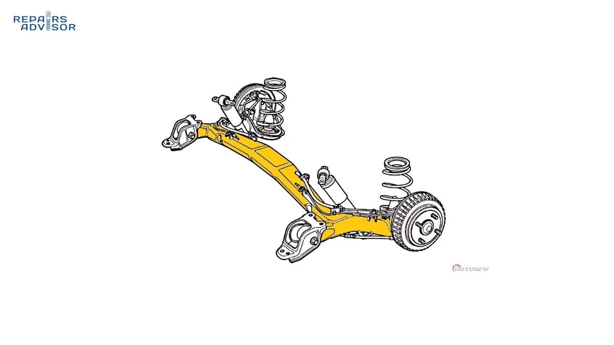
Torsion beam suspension is a semi-independent rear suspension system that uses an H-shaped or C-shaped metal beam to connect the left and right trailing arms. Unlike a solid axle that rigidly links both wheels, or fully independent suspension where each wheel moves completely separately, torsion beam occupies the middle ground. The crossbeam twists (torsionally flexes) to allow some independence between wheels while maintaining a structural connection. This clever engineering compromise delivers functional ride quality and handling at significantly lower cost and complexity than multi-link independent systems.
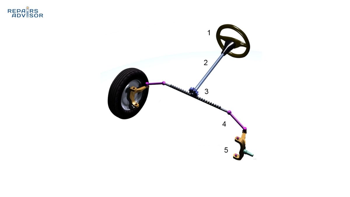
The design appears almost exclusively on rear axles of front-wheel-drive vehicles. You won’t find it handling steering duties or power delivery—its strength lies in balancing cost-effectiveness with space efficiency. Major automakers including Volkswagen, Mazda, Ford, Peugeot, and Toyota have deployed torsion beam suspension across their compact vehicle lineups. The 2019+ Mazda 3, for instance, switched from multi-link to an optimized torsion beam design that delivers near-independent ride quality through varying beam thickness along its length.
For DIY enthusiasts and professional mechanics alike, torsion beam systems offer maintenance advantages through their simplicity. With only five major components compared to ten-plus in multi-link setups, there are 50% fewer potential failure points to diagnose and service. That said, when issues do arise—particularly bushing wear or beam damage—the interconnected nature of the system means problems can affect handling balance more noticeably than isolated component failures in independent suspension. Understanding the complete suspension system architecture provides essential context for how torsion beams integrate with your vehicle’s overall dynamics.
Core Components and Construction
The beauty of torsion beam suspension lies in its elegant simplicity. Where multi-link suspension systems require multiple control arms, pivot points, and complex geometry calculations, a torsion beam accomplishes similar functions with remarkably few parts. Let’s examine each component and understand why this minimalist approach works.
The H-Shaped or C-Shaped Beam
At the heart of the system sits a single piece of stamped and welded low-carbon steel formed into an H or C shape. This isn’t a sophisticated assembly of multiple components—it’s literally one integrated structural element. The simplicity is deceptive, though, because this beam must satisfy competing engineering demands. It needs sufficient strength to resist unwanted wheel movement during acceleration, braking, and cornering, yet it must retain enough torsional flexibility to allow the wheels some independence over one-wheel bumps.
The crossbeam connecting the left and right sides gives the system its name and its key functional characteristic. When the beam twists under load, it provides a natural anti-roll bar effect without requiring a separate stabilizer bar and end links. This integrated approach saves weight, reduces parts count, and eliminates additional failure points. Modern manufacturers have refined beam design extensively—Mazda’s approach on the current Mazda 3 uses varying thickness along the beam’s length to fine-tune its torsional characteristics, creating nearly independent wheel behavior during most driving conditions.
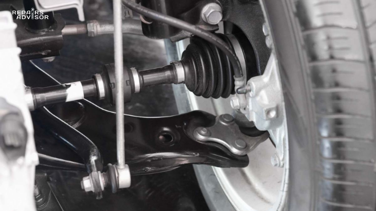
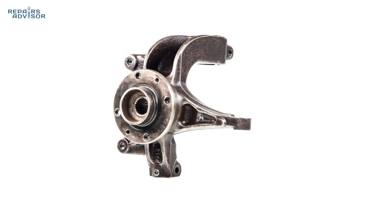
Trailing Arms and Structural Integration
The trailing arms extend forward from the beam to connect with the vehicle’s chassis. In most torsion beam designs, these arms are welded directly to the crossbeam with no pivot points at that junction. This rigid connection means the beam and trailing arms function as a unified structure. Each trailing arm carries the wheel hub, brake assembly, and mounting points for the coil spring and shock absorber.
The welded connection between beam and trailing arms creates the system’s semi-independent characteristic. When one wheel encounters a bump, the trailing arm tries to pivot upward around its front mounting points. This movement forces the crossbeam to twist, which in turn affects the opposite trailing arm to some degree. The amount of influence depends on the beam’s torsional stiffness—a carefully calculated parameter that engineers tune to balance ride comfort against handling precision.
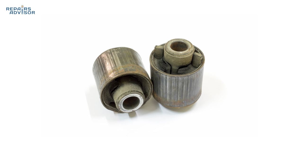
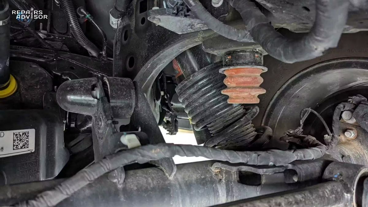
Mounting Bushings: The Critical Connection
All the forces from both rear wheels—vertical impacts, lateral cornering loads, longitudinal acceleration and braking forces—ultimately channel through just two mounting bushings per side where the trailing arms attach to the vehicle chassis. These metal-rubber bushings face an incredibly difficult job. They must isolate road vibrations and noise to maintain cabin comfort, yet they can’t be so soft that they allow excessive wheel movement that would compromise handling and tire wear.
This engineering challenge leads to a characteristic compromise in torsion beam systems. The bushings are typically rather stiff compared to those in independent suspension systems. This stiffness maintains proper wheel control and handling response, but it also transmits more road noise and vibration to the cabin. As these bushings age and deteriorate from exposure to heat, moisture, road salt, and mechanical stress, their condition becomes critical. Worn bushings don’t just affect comfort—they can noticeably degrade handling balance and cause abnormal tire wear patterns. The principles of bushing function in torsion beam applications mirror those in other suspension designs, though the load concentration makes regular inspection particularly important.
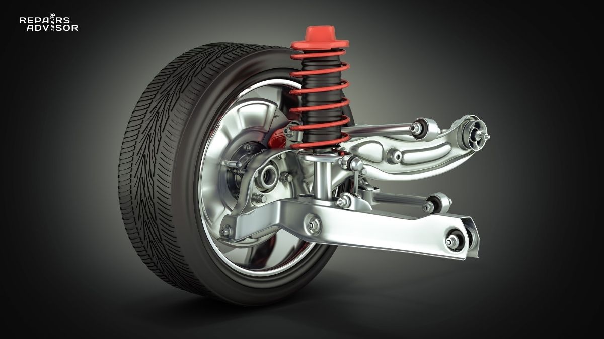
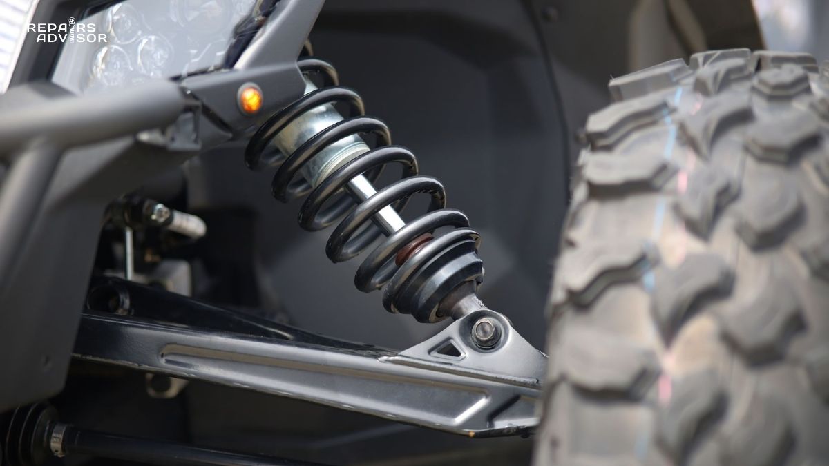
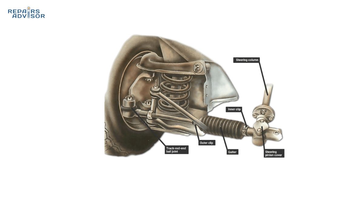
Springs and Shock Absorbers
Suspension springs in torsion beam systems typically mount on pads alongside the stub axle rather than on separate towers. Many designs use a coil-over configuration where the spring surrounds the shock absorber, creating a compact integrated unit. This packaging approach contributes to the system’s space efficiency—by positioning springs and shocks further outboard and lower in the chassis, designers free up valuable interior volume for passengers and cargo.
The shock absorber mounting location in many torsion beam designs provides a high motion ratio, meaning small wheel movements translate to larger damper travel. This theoretically improves damping performance compared to mounting positions with lower motion ratios. In some cost-optimized designs, the shock absorber serves double duty as a restraint strap. When the suspension droops to full extension, the shock’s physical length prevents the trailing arm from dropping so far that the coil spring becomes completely unloaded and falls out of position—an elegant solution that eliminates the need for a separate retention mechanism.
How Torsion Beam Suspension Works
Understanding torsion beam operation requires examining three different scenarios: both wheels moving together, single-wheel events, and body roll during cornering. Each situation reveals different aspects of the system’s semi-independent nature.
Both Wheels Moving Together
When both rear wheels encounter the same road input simultaneously—hitting a speed bump, for example—the torsion beam system behaves remarkably like fully independent suspension. Both trailing arms pivot upward around their front mounting points in unison. Since both sides move equally, the crossbeam experiences no twisting force. It simply rises with the trailing arms, acting as a rigid connector rather than a torsional element.
In this scenario, wheel camber (the inward or outward tilt) and toe (the direction the wheels point) remain stable and consistent. The suspension compresses and rebounds smoothly, with the springs and shocks controlling the motion. This parallel-wheel-bump behavior is why many drivers never perceive any disadvantage from torsion beam suspension during normal driving on smooth roads. The system responds just as an independent setup would.
Single-Wheel Bumps and the Semi-Independent Character
The torsion beam’s unique personality emerges when one wheel hits a bump while the other travels over smooth pavement. As the impacted wheel’s trailing arm tries to rise, it must twist the crossbeam because the opposite wheel remains at a different height. This is where “torsion” becomes more than just a name—the beam resists twisting, but it does flex to accommodate the unequal wheel positions.
Here’s where semi-independence becomes evident. The twisting beam transmits some force to the opposite wheel’s trailing arm, causing it to react slightly even though it hasn’t encountered an obstacle. This mechanical coupling means the unaffected wheel doesn’t remain completely neutral—it experiences a small sympathetic movement. The degree of this interaction depends on the beam’s torsional stiffness, which engineers carefully calibrate during development.
For passengers, this means road irregularities on one side of the vehicle cause minor disturbances on the opposite side. True independent suspension isolates these inputs better, keeping the unaffected wheel more neutral. The difference is most noticeable to rear seat passengers traveling on rough roads with significant one-sided bumps or potholes. That said, modern optimized torsion beam designs have minimized this effect considerably. The Mazda 3’s implementation, for instance, uses strategic thickness variations along the beam to create zones of different torsional stiffness, allowing more independence during typical driving while maintaining structural integrity and anti-roll function.
Cornering Dynamics and Camber Behavior
During cornering, the torsion beam system reveals both its limitations and its built-in advantages. As the vehicle’s body rolls toward the outside of the turn, the outer rear wheel compresses while the inner wheel extends. This creates maximum demand for beam twisting—the two wheels are moving in opposite directions with significant force.
The beam’s torsional resistance during this scenario effectively creates an anti-roll bar function without requiring a separate stabilizer component. As it twists to accommodate the body roll, it resists that twisting motion, limiting how much the vehicle leans. This is a genuine engineering advantage: one less component to manufacture, install, maintain, and potentially fail.
However, the camber behavior during single-wheel or cornering events presents a characteristic of torsion beam systems. When one wheel rises relative to the other, it gains negative camber (tilts inward at the top), while the wheel on the opposite side gains positive camber (tilts outward at the top). The rigid beam connection means the camber changes are coupled—you can’t optimize one wheel’s angle without affecting the other. This differs from double wishbone or multi-link systems where each wheel’s camber curve can be tuned independently.
For most everyday driving, this coupled camber behavior creates no issues. In aggressive cornering, though, it becomes more significant. Heavy cornering loads shift weight dramatically onto the outside rear wheel. The combination of body roll, weight transfer, and the beam’s camber characteristics can lead to the inside rear wheel lifting off the ground during very aggressive maneuvers. You’ve probably seen viral videos of hot hatches catching air with an inside rear wheel during tight cornering—that’s the torsion beam’s semi-dependent nature at its extreme limit.
Interestingly, the beam’s position along the trailing arms significantly affects suspension behavior. When positioned near the chassis pivot points, the system acts more like simple trailing arms with minimal interaction between sides. Positioned near the wheel centers, it behaves closer to a solid axle. The most common placement is in the middle, which creates what suspension engineers call “virtual semi-trailing arm geometry.” Right at the beam’s center is a neutral point that doesn’t twist during cornering—this point effectively acts like the inner pivot bush of a semi-trailing arm suspension, giving the system its characteristic handling dynamics.
Advantages of Torsion Beam Design
Torsion beam suspension has earned its widespread adoption through genuine advantages that matter for specific vehicle applications. These benefits aren’t just theoretical—they translate to tangible improvements in manufacturing efficiency, vehicle packaging, and ownership experience.
Manufacturing and Cost Benefits
The parts count advantage is immediately obvious: a torsion beam system uses roughly five major components total, compared to ten or more in a comparable multi-link setup. Each control arm, ball joint, bushing, and link in an independent suspension represents material cost, manufacturing complexity, assembly time, and potential quality variation. Eliminating half those components has cascading benefits throughout the production process.
From a reliability perspective, fewer parts mean fewer potential failure points. A multi-link system might have four or more bushings per side, multiple ball joints, and various linkages—each capable of wearing out independently. The torsion beam concentrates wear into primarily two mounting bushings per side and the shock absorbers. This doesn’t make the system immune to problems, but it does simplify diagnosis and reduces the number of components requiring periodic inspection.
The production efficiency extends to assembly. A torsion beam typically arrives at the assembly line as a pre-assembled module. Workers can install the entire rear suspension—beam, trailing arms, springs, shocks, and all—in one operation. Compare this to multi-link systems that may require installing each control arm individually, setting toe adjustments, and verifying complex geometry. The simplified assembly process saves labor hours and reduces potential installation errors.
Packaging Advantages and Interior Space
For compact vehicle designers, space efficiency is paramount. Every cubic inch consumed by mechanical components is space lost to passengers or cargo. Torsion beam systems excel here through their compact, low-mounted design. The beam sits comparatively lower in the chassis than the subframes required for multi-link suspensions, and it positions springs and shocks further outboard.
This packaging creates measurable benefits. The lower suspension mounting allows a lower cargo floor in hatchbacks and wagons without compromising ground clearance. The outboard spring positions free up space where the wheel wells would otherwise intrude significantly into the trunk. For rear-seat passengers, the simplified structure beneath the floor allows better foot well design and potentially more legroom. These aren’t trivial gains—in competitive compact car segments, a few extra cubic feet of cargo capacity or an additional inch of rear legroom can be significant differentiators.
Built-In Anti-Roll Function
The torsional stiffness that gives the beam its name serves as a natural anti-roll bar. During body roll, the twisting beam resists that motion, providing lateral stability without additional components. Traditional independent suspensions require a separate stabilizer bar linking the two sides—another part to design, manufacture, install, and maintain. Some performance-oriented multi-link systems use adjustable anti-roll bars with additional complexity and cost. The torsion beam’s integrated approach eliminates all of this.
From a weight perspective, this matters. Removing a stabilizer bar, its mounting brackets, and end links saves several pounds of unsprung weight—weight carried by the suspension rather than supported by it. Lower unsprung weight generally improves ride quality and wheel control, allowing the suspension to react more quickly to road inputs.
Durability and Maintenance Simplicity
The torsion beam itself is a solid piece of steel with no internal mechanisms, sealed bearings (except in some French designs), or hydraulic components. Short of physical damage or catastrophic fatigue failure, the beam structure itself requires essentially no maintenance. This durability contributes to long service life—a well-designed torsion beam system can last the vehicle’s lifetime with only routine shock and spring replacement.
When maintenance is needed, the system’s simplicity aids diagnosis and repair. A technician examining a torsion beam system primarily checks bushing condition, shock absorber function, spring integrity, and structural damage. There are no multiple bushings per side to assess independently, no ball joints to inspect, and fewer geometric adjustments to verify. This translates to lower diagnostic time and often reduced repair costs compared to addressing issues in complex multi-link suspensions.
Performance Potential
Perhaps the most surprising advantage is that torsion beam suspension, despite its cost-focused reputation, can deliver genuine performance. The evidence is compelling: Volkswagen used torsion beams for years on Golf GTI models that defined the hot hatch segment. The Honda Civic Type R FK2 set Nürburgring lap records while running a torsion beam rear. The Renault Mégane RS and Peugeot 308 GTi have proven their track credentials repeatedly. The Peugeot 308 II achieved an 82 km/h moose test result—only 3 km/h slower than the legendary Citroën Xantia Activa’s world record of 85 km/h—despite competing against vehicles with more sophisticated multi-link rear suspensions.
This performance potential comes down to engineering execution. A properly designed torsion beam with appropriate stiffness characteristics, quality bushings, well-tuned springs and shocks, and careful integration with the vehicle’s overall dynamics can deliver excellent handling. The simpler mechanical setup can actually aid performance in some ways—fewer pivot points mean fewer opportunities for compliance and slop to develop, potentially giving a more direct, connected feel. The key word, though, is “properly designed.” A poorly executed torsion beam will feel crude and compromised, just as a poorly executed multi-link system will underwhelm.
Limitations and Common Issues
Honest assessment of torsion beam suspension requires acknowledging its inherent limitations and understanding failure patterns. These aren’t fatal flaws that disqualify the design—they’re tradeoffs that matter more in some applications than others.
The Semi-Dependent Compromise
The fundamental limitation stems from the mechanical coupling between wheels. No matter how sophisticated the beam design, the left and right wheels influence each other more than in true independent suspension. When one wheel encounters a road irregularity, the opposite wheel cannot remain completely neutral. This coupling transmits disturbances across the vehicle’s width, which rear passengers perceive as reduced isolation from road imperfections.
The practical impact depends on driving conditions. On smooth highways with gentle curves, most drivers would struggle to detect any difference between torsion beam and multi-link suspension. On rough urban streets with potholes concentrated on one side, or mountain roads with severe one-sided bumps, the torsion beam’s interconnected nature becomes more apparent. The ride quality can feel busier, with more secondary motions as disturbances on one side partially transmit to the other.
Engineers have made remarkable progress in minimizing this effect through optimized beam profiles and strategic bushing compliance, but there remains a fundamental limit. A torsion beam will never isolate wheels as completely as independent suspension can. For manufacturers prioritizing absolute ride quality refinement in premium vehicles, this limitation often justifies the added cost and complexity of multi-link designs.
Limited Adjustability and Modification Constraints
Enthusiasts who enjoy modifying suspension characteristics face frustrations with torsion beam systems. The camber curve—how wheel tilt changes through suspension travel—is essentially fixed by the beam’s position and geometry. Unlike control arm systems where you can adjust mounting points or substitute arms with different geometries, the torsion beam’s welded construction offers no such flexibility.
Toe adjustment presents similar challenges. Most torsion beam systems provide minimal toe adjustment capability, and the adjustment method can be tedious. Rather than simple eccentric bolts or adjustable links, many designs require adding or removing shim washers between the beam’s hub mounting surface and the wheel carrier—a time-consuming process requiring repeated assembly and test cycles. Some systems offer essentially no toe adjustment at all; what you have is what you get.
The modification toolkit is limited primarily to springs, shock absorbers, and bushings. Want to add negative camber for better cornering grip? You’re generally out of luck unless you’re willing to manufacture custom shim kits—and even then, options are limited. Interested in fine-tuning toe curves for sharper turn-in response? The torsion beam resists such adjustments. For those who see suspension modification as part of vehicle ownership enjoyment, these constraints can be deal-breakers. For owners content with manufacturer specifications, they’re irrelevant.
Common Failure Points
While torsion beam systems benefit from overall simplicity, certain components bear concentrated loads and wear predictably over time. Understanding these failure patterns helps with preventive maintenance and early diagnosis.
Mounting Bushing Degradation
The mounting bushings where trailing arms connect to the chassis experience extreme operating conditions. They must accommodate suspension articulation while enduring vertical impacts, lateral cornering forces, and longitudinal acceleration/braking loads—all channeled through just two bushings per side. Add environmental assault from road salt, temperature cycles, ozone exposure, and moisture, and these bushings face a challenging service life.
Worn bushings manifest in several ways. Knocking or clunking noises over bumps are often the first symptom, as the degraded rubber allows metal-to-metal contact within the bushing assembly. The vehicle’s rear end may feel vague or loose, with delayed response to steering inputs. Abnormal tire wear patterns—particularly inner or outer edge wear—suggest the bushings are allowing excessive wheel movement. In severe cases, the worn bushings permit enough play that wheel alignment shifts noticeably during acceleration, braking, or cornering.
The interconnected nature of torsion beam suspension means bushing wear affects both sides’ behavior. Even if only one bushing has failed, the beam’s rigid connection transmits the resulting geometry changes across the entire rear axle. This is why bushing condition inspections should examine all mounting points comprehensively rather than looking for isolated problems.
French Car Special Consideration: Needle Bearing Failures
Torsion beam systems in some French vehicles—particularly certain Citroën and Peugeot models—use internal needle bearings within the beam structure itself. These bearings provide additional articulation capability, but they’re vulnerable to contamination. If the protective seals deteriorate and allow dirt, water, or road salt to enter, the needle bearings degrade rapidly.
Symptoms include abnormal noises from the rear suspension, unnatural tilting of the rear wheels toward the vehicle body, or the entire vehicle leaning to one side. The internal bearing design makes these failures more difficult to repair than simple bushing replacement. Often, the entire beam assembly requires removal for service or replacement—a labor-intensive repair that motivates particularly attentive preventive maintenance for these systems.
Structural Beam Damage
The torsion beam’s solid steel construction provides excellent durability under normal operating conditions, but it’s vulnerable to severe side impacts. A strong lateral hit to a rear wheel—striking a curb during parking, for instance, or side impact during an accident—can bend or warp the beam. Unlike multi-link systems where a single control arm might absorb the damage, the torsion beam’s one-piece structure means deformation affects the entire assembly.
Welded joints where the crossbeam connects to the trailing arms represent another potential failure point. Repeated stress cycles over years and tens of thousands of miles can develop fatigue cracks at these welds. Road salt and moisture accelerate corrosion, which reduces the effective cross-section of the beam and concentrates stress. Severe corrosion combined with fatigue loading can eventually lead to structural failure.
The beam also experiences a phenomenon similar to spring settling. Over time, the steel “relaxes” under constant load, gradually reducing rear ride height. The torsion bar design allows for some compensatory adjustment by reinstalling the bars in different positions, but this is a temporary solution. Eventually, accumulated fatigue stress and corrosion damage will require beam replacement.
Secondary Component Wear
Like any suspension system, torsion beam setups experience typical component wear. Shock absorbers develop oil leaks, lose damping efficiency, and eventually fail. Springs can sag from age or overloading. Coil spring coating can chip away, allowing corrosion that weakens the spring. These are universal suspension wear patterns not unique to torsion beam designs, but they require the same attention and periodic replacement.
Noise, Vibration, and Harshness Challenges
The relatively stiff mounting bushings necessary for proper wheel control create an inherent NVH (Noise, Vibration, and Harshness) tradeoff. More compliant bushings would improve isolation but allow excessive wheel movement and imprecise handling. Stiffer bushings maintain control but transmit more road noise and vibration to the cabin. This balance point represents a fundamental engineering challenge in torsion beam design.
The system’s limited recession compliance—how much the wheel can move rearward when hitting an obstacle—can cause harsher impact sensations over sharp bumps compared to well-designed multi-link systems. The wheel essentially has less ability to “give” when striking a pothole edge or road debris. Combined with the bushing stiffness, this can create a busier, less refined ride quality on poor road surfaces.
Modern torsion beam designs address these issues through sophisticated bushing design, careful beam profile optimization, and comprehensive damper tuning. The results can be remarkably good—the current Mazda 3’s torsion beam rear delivers ride quality that many reviewers compare favorably to multi-link systems. However, achieving this level of refinement requires extensive development investment, and not all torsion beam implementations reach this standard.
Maintenance and Inspection
Torsion beam suspension benefits from mechanical simplicity, but its interconnected design means small problems can affect overall behavior significantly. Regular inspection combined with prompt attention to warning signs helps maintain proper function and prevents minor issues from cascading into expensive repairs.
Regular Inspection for DIY Enthusiasts
Intermediate-level DIY mechanics can perform meaningful visual inspections without specialized tools. With the vehicle safely supported on jack stands, examine the mounting bushings where trailing arms connect to the chassis. Look for visible cracks, tears, or separation in the rubber material. The bushing should appear uniform and well-bonded to its metal inner and outer shells. Any oil or grease residue might indicate shock absorber leakage, though confirm the source—sometimes front suspension leaks drip onto rear components and cause confusion.
Check for any obvious deformation in the beam structure itself. The crossbeam should be straight and symmetrical. Trailing arms should be parallel and show no signs of bending or twisting. Look closely at welded joints for crack initiation—though small fatigue cracks are difficult to detect visually without proper inspection methods. Examine spring seats and shock absorber mounting points for rust or damage that could allow movement or noise.
Perform a basic bounce test to assess shock absorber function. Push down firmly on each rear corner of the vehicle and release. The suspension should rebound to its normal position and stabilize after one or two cycles. Continued oscillation suggests worn shocks. This test has limitations—it can identify severely failed dampers but won’t detect moderate degradation. However, it’s a useful quick check between professional inspections.
Pay attention to unusual noises during driving. Any new or changing sounds from the rear suspension deserve investigation. Knocking or clunking over bumps often indicates bushing wear. Squeaking might suggest spring seat issues or binding in the suspension movement. Metallic rattling could mean loose fasteners or worn shock mounting hardware.
Monitor rear ride height over time. Measure from the ground to a consistent reference point on the body—the wheel arch edge works well. Record measurements periodically to track any gradual sagging, which suggests spring fatigue or bushing settlement. Uneven ride height side-to-side could indicate a bent beam, failed spring, or asymmetric bushing wear.
Watch for abnormal tire wear patterns. Inner or outer edge wear on rear tires, when fronts wear normally, suggests rear suspension geometry problems—often from worn bushings allowing wheel position to shift. Regular tire rotation helps identify rear-specific wear patterns that might otherwise go unnoticed until tires are replaced.
When Professional Help Becomes Necessary
While visual inspection and basic checks are DIY-appropriate, certain diagnostic procedures and repairs require professional expertise and specialized equipment. The safety-critical nature of suspension work makes proper execution essential.
Any suspected structural damage to the torsion beam itself requires professional assessment. A shop with proper alignment equipment can measure rear wheel geometry precisely and compare it to manufacturer specifications. Bent beams cause subtle geometry changes that simple visual inspection might miss but that can significantly affect handling and tire wear. Professional diagnostic procedures apply similar principles to torsion beam systems as to other suspension designs.
Bushing replacement, while conceptually straightforward, often requires special tools. Many designs use pressed-in bushings that demand hydraulic presses and proper fixtures to remove and install without damaging the trailing arms or beam structure. Even slip-fit bushings that appear simple to replace require precise torque specifications and sometimes specific installation sequences. Improper installation can cause premature failure or create handling problems.
Any rear suspension repair that affects wheel position—bushing replacement, beam replacement, spring changes—mandates subsequent wheel alignment. Proper alignment requires specialized equipment that measures all four wheels simultaneously and references manufacturer specifications. DIY alignment attempts rarely achieve acceptable results and can leave the vehicle unsafe or cause accelerated tire wear.
After any side impact or suspected beam damage, professional inspection is mandatory. Even impacts that seem minor can bend the beam enough to cause problems. Without proper measurement tools, you cannot verify that the structure remains within safe tolerances. Given that rear suspension affects vehicle stability and control, err on the side of caution—professional verification after impacts is cheap insurance against potential safety issues.
French vehicles with internal needle bearing systems require special attention. If you notice symptoms suggesting bearing problems—unusual noises, wheel tilt, or vehicle lean—seek service from technicians familiar with these specific designs. The internal bearing service requires beam disassembly that’s impractical for most DIY shops, and proper repair may require specialized parts or complete beam replacement.
Preventive Maintenance Strategies
Several practices extend torsion beam suspension life and help catch problems early. Regular undercarriage cleaning, particularly in winter climates where road salt is used, removes corrosive materials before they can degrade bushings, accelerate metal fatigue, or cause seal failures. Many automatic car washes offer underbody spray options—use them regularly during salt season.
Avoid chronic overloading, which accelerates wear on all suspension components. Every vehicle has a maximum cargo weight rating for good reasons. Consistently exceeding that rating strains bushings, fatigues metal structures, and causes premature spring sagging. If you regularly need to carry heavy loads, consider a vehicle designed for that duty rather than pushing a compact car beyond its limits.
Replace shock absorbers at manufacturer-recommended intervals, typically between 50,000 and 80,000 miles depending on driving conditions. Worn shocks increase dynamic loads on all suspension components, accelerating wear throughout the system. They also degrade handling and braking performance—worn shocks increase stopping distances measurably. Fresh dampers improve ride quality, handling, and safety while protecting other suspension components from excessive stress.
Address small issues promptly before they cascade. A single worn bushing might seem minor, but the resulting geometry change affects tire wear, handling balance, and loads on other components. Early bushing replacement is relatively inexpensive and straightforward. Delaying repair until the worn bushing causes secondary damage—bent beam, damaged wheel bearing, or destroyed tires—turns a modest repair into a major expense.
Critical Safety Warning: Suspension work directly affects vehicle control, stability, and safety. While visual inspections and basic assessments are appropriate DIY activities, repairs should be performed only by qualified technicians with proper tools, technical specifications, torque values, and alignment equipment. Improper suspension work can create dangerous handling characteristics that may not become apparent until an emergency maneuver reveals the problem. If you notice any changes in handling behavior, ride quality, or hear unfamiliar noises, have the suspension inspected promptly by professionals. Early detection and proper repair prevent minor issues from developing into safety hazards.
Understanding Your Vehicle and Making Informed Decisions
Torsion beam suspension represents an engineering compromise that works exceptionally well for its intended applications. It’s not an inferior design relegated to the cheapest vehicles—it’s an optimized solution that balances cost, space efficiency, reliability, and performance for compact front-wheel-drive applications. Understanding whether your vehicle uses this system, what to expect from it, and how it compares to alternatives helps set realistic expectations and informs maintenance decisions.
Many popular vehicles use torsion beam rear suspension. Various trim levels of the Volkswagen Golf—particularly base and mid-range models—have employed the design across multiple generations. The 2019 and newer Mazda 3, in a move that surprised industry observers, switched to an optimized torsion beam from the previous generation’s multi-link setup. The Toyota Corolla Cross uses a torsion beam despite sharing its platform with the Corolla sedan that offers multi-link on some variants. Honda has used torsion beam on certain Civic models, particularly lower-specification variants. Peugeot 308, Renault Mégane, and Ford Focus (in some markets and configurations) all feature the design. Even some Volkswagen and Ford performance variants prove the system’s capability.
The critical factor isn’t whether a vehicle has torsion beam suspension—it’s how well that suspension has been engineered and integrated. A carefully developed torsion beam with appropriate stiffness characteristics, quality bushings, well-matched springs and dampers, and proper chassis tuning can deliver excellent results. A cost-minimized implementation with minimal development investment will feel crude. When evaluating vehicles, focus on the total driving experience rather than suspension type alone. Many automotive journalists have been pleasantly surprised by refined torsion beam implementations after expecting compromised ride quality.
For vehicle modification enthusiasts, be realistic about the system’s limitations. If extensive suspension tuning is part of your ownership plans—adjustable camber, multiple toe settings, sophisticated anti-roll bar tuning—torsion beam suspension will frustrate you with its limited adjustability. The modification toolkit is essentially springs, shocks, and bushings. That said, these three variables still allow meaningful changes to ride quality and handling characteristics. High-quality performance shocks, properly rated lowering springs, and upgraded bushings can transform a torsion beam car’s dynamics within the system’s inherent constraints.
If you’re considering a vehicle purchase and prioritizing absolute ride quality refinement, particularly if you frequently travel over poor road surfaces with rear passengers, multi-link suspension offers genuine advantages. The superior wheel isolation translates to measurably better rear seat comfort on rough roads. However, if your priorities emphasize reliability, maintenance simplicity, cargo space, and overall value, torsion beam suspension delivers compelling benefits. Many owners never perceive any disadvantage in normal driving conditions.
When maintenance or repair becomes necessary, approach torsion beam suspension work with appropriate respect for its interconnected nature and safety-critical function. The simplicity aids diagnosis—you’re examining fewer components—but the mechanical coupling means problems affect overall behavior more than isolated failures in independent suspension. Any change in ride quality, new noises, unusual handling characteristics, or visible damage warrants prompt professional inspection.
If you notice the vehicle feels vague or loose in the rear during lane changes, or if you hear knocking sounds over bumps that weren’t there previously, bushing wear is the likely culprit. Have them inspected before the worn bushings cause secondary damage or safety issues. If ride height seems lower than normal, or if the vehicle leans to one side when viewed from behind on level ground, spring fatigue or structural problems may exist. After any side impact—even seemingly minor curb strikes during parking—verify the beam hasn’t been bent. The integrated structure means even moderate deformation can affect handling substantially.
For those seeking deeper technical understanding, exploring related suspension system technologies provides valuable context for how torsion beam design fits within the broader landscape of automotive engineering. Understanding the tradeoffs between different suspension philosophies—from simple beam axles to sophisticated multi-link systems and even active suspension—helps appreciate why torsion beam continues thriving decades after its introduction.
The key insight is that torsion beam suspension isn’t a compromise that manufacturers settle for reluctantly—it’s an intentional design choice that delivers specific benefits. Those benefits matter enormously in compact vehicle applications where space, cost, and reliability take priority. The system’s simplicity isn’t crudeness; it’s elegant efficiency. Its limitations are real but well-understood and manageable within appropriate use cases. Judged fairly on its intended merits rather than compared unfavorably to high-end solutions designed for different priorities, torsion beam suspension represents excellent engineering that has served millions of vehicles superbly for decades and will continue doing so for years to come.