The Positive Crankcase Ventilation (PCV) system is one of the most underappreciated yet essential components in your vehicle’s engine management system. While it may seem like a simple emissions control device, the PCV system plays a critical role in maintaining engine longevity, fuel efficiency, and overall performance. Understanding how this system works and why it matters can help you prevent costly engine damage and keep your vehicle running smoothly for years to come.
What Makes the PCV System Essential
The PCV system serves multiple vital functions that directly impact your engine’s health and performance. First and foremost, it prevents the buildup of harmful crankcase pressure that naturally occurs during combustion. Every time your engine’s pistons move through their compression and power strokes, small amounts of combustion gases—called “blowby”—escape past the piston rings and enter the crankcase. Without proper ventilation, this pressure would damage seals, gaskets, and potentially cause catastrophic engine failure.
Beyond pressure regulation, the PCV system acts as a crucial emissions control mechanism. Instead of venting these harmful gases directly into the atmosphere, the system routes them back into the intake manifold where they can be reburned in the combustion chamber. This process significantly reduces hydrocarbon emissions while also improving fuel efficiency by recapturing unburned fuel vapors.
The system also plays an important role in moisture management. Combustion naturally produces water vapor as a byproduct, and this moisture can accumulate in the crankcase. The PCV system helps evacuate this moisture before it can combine with combustion byproducts to form corrosive acids that attack engine bearings, cylinder walls, and other internal components. This moisture removal is particularly critical during short trips and cold weather operation when the engine doesn’t reach full operating temperature.
For DIY enthusiasts working on engine maintenance, understanding the PCV system is essential because it directly affects oil quality and engine cleanliness. A properly functioning PCV system helps keep your engine oil cleaner longer by reducing contamination from combustion gases. When the system fails, you’ll notice faster oil degradation, increased sludge formation, and accelerated wear on critical engine components.
Professional mechanics know that PCV system issues can manifest as a wide range of symptoms that mimic other problems, making proper diagnosis critical. From rough idle to oil consumption, many common complaints trace back to a malfunctioning PCV valve or clogged system passages. The system’s simplicity makes it easy to overlook during diagnostics, yet its impact on engine performance is profound.
PCV System Parts and Construction Explained
Understanding the components that make up your PCV system helps you diagnose issues and perform proper maintenance. While the system appears simple, each component plays a specific role in the ventilation process.
The PCV Valve
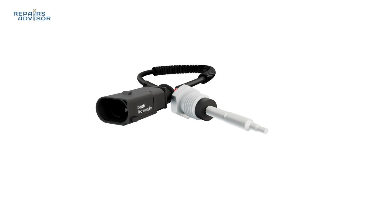
The heart of the system is the PCV valve itself—a spring-loaded, one-way valve that regulates the flow of crankcase gases back into the intake manifold. Most PCV valves are small cylindrical devices, typically 3-4 inches long, with a tapered pintle inside that moves in response to intake manifold vacuum. The valve contains a spring that controls the pintle’s position, allowing it to meter gas flow based on engine operating conditions.
Modern PCV valves are precisely calibrated for specific engine applications. The spring rate, pintle taper, and internal passages are engineered to provide the correct flow at idle, cruise, and wide-open throttle conditions. This calibration is why using the correct replacement valve is critical—an incorrect valve can cause rough idle, stalling, or excessive oil consumption.
High-quality PCV valves feature durable materials that resist the corrosive environment inside the crankcase. The valve body is typically made from reinforced plastic or metal, while internal components may include stainless steel or specially coated metals. The valve’s grommets and seals must withstand constant exposure to oil vapor, heat, and acidic combustion byproducts.
Breather System and Fresh Air Supply
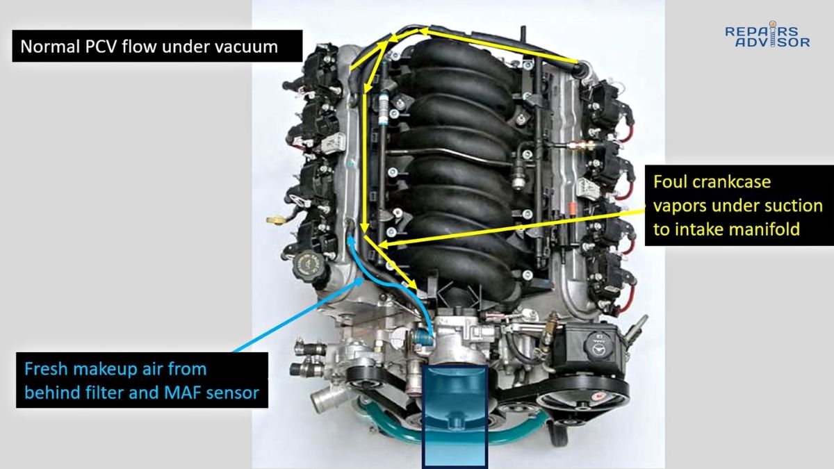
The PCV system requires a source of fresh air to create proper flow through the crankcase. Most engines use a breather hose connected to the air intake system, typically downstream of the air filter. This connection allows filtered air to enter the crankcase, sweep through the internal passages, and carry contaminants toward the PCV valve.
Some vehicles incorporate a separate breather element or filter in the valve cover. These filters prevent oil mist from being drawn into the intake system while still allowing air flow. On turbocharged engines, the breather system design becomes more complex due to the positive pressure created by boost—these systems often include oil separators to prevent turbo oil contamination.
The breather hose itself deserves attention during maintenance. These hoses experience constant exposure to oil vapor and heat cycling, which can cause deterioration over time. Cracked or collapsed breather hoses disrupt proper system operation and can lead to oil leaks or contamination issues.
Connecting Hoses and Passages
The PCV valve connects to the intake manifold through a dedicated hose, which must maintain integrity under varying vacuum and temperature conditions. This hose typically runs from the valve cover to a port on the intake manifold, carburetor, or throttle body. The routing varies by engine design, but the principle remains the same—providing a controlled path for crankcase gases to enter the combustion process.
Inside the engine, dedicated passages machined into the block and cylinder heads allow gases to flow from the crankcase to the valve cover where the PCV valve is mounted. These internal passages can become restricted over time due to sludge buildup, particularly in engines that experience extended oil change intervals or use low-quality oil.
For those working with diesel engines, the crankcase ventilation system often includes additional components such as oil separators and cyclonic separators to handle the higher volume of blowby gases typical in compression-ignition engines.
Valve Cover Integration
Most modern engines integrate the PCV valve directly into the valve cover assembly. The valve may be threaded into a grommet, pressed into a molded opening, or incorporated into a dedicated mounting boss. This integration simplifies installation and ensures proper sealing, but it can also make replacement more challenging on some vehicles.
The valve cover itself plays a role in the PCV system by providing a collection chamber for crankcase gases and oil mist. Internal baffles help separate oil from the gas stream before it reaches the PCV valve, reducing oil consumption and preventing contamination of the intake system. Understanding valve cover design helps when performing maintenance or diagnosing oil leaks related to PCV system issues.
How PCV System Works: Step-by-Step Operation
The PCV system’s operation varies based on engine load and operating conditions, demonstrating sophisticated design despite its apparent simplicity. Understanding these operational modes helps diagnose system problems and appreciate why proper function is critical.
Idle and Light Load Operation
At idle, engine vacuum is at its highest level, typically 17-21 inches of mercury (in-Hg) on a healthy engine. This strong vacuum would normally pull excessive crankcase gases into the intake manifold if left unregulated. The PCV valve responds to this high vacuum by restricting flow—the spring inside the valve holds the pintle in a position that limits the size of the passage through which gases can flow.
During this mode, fresh air enters the crankcase through the breather system, flows through the engine’s internal passages, picks up any blowby gases and moisture, and exits through the PCV valve at a controlled rate. The metered flow prevents the engine from running too lean while still providing adequate crankcase ventilation. This balance is why a stuck or incorrect PCV valve often causes rough idle—the air-fuel mixture becomes disrupted.
The limited flow at idle also prevents engine oil from being drawn into the intake system. Oil vapor naturally rises to the valve cover area, and without proper restriction, manifold vacuum could pull this oil mist through the PCV valve, causing oil consumption and fouling issues. The valve’s restriction at idle keeps oil where it belongs while still managing crankcase pressure.
Cruise and Moderate Load Conditions
As engine load increases and throttle opening widens, manifold vacuum decreases—typically to 8-12 in-Hg during steady cruise conditions. The PCV valve responds to this lower vacuum by allowing its spring to move the pintle to a position that opens the passage further. This increased flow matches the higher volume of blowby gases produced during moderate load operation.
During cruise, the engine produces more blowby because cylinder pressures are higher than at idle, forcing more combustion gases past the piston rings. The PCV system automatically compensates by increasing flow rate, maintaining proper crankcase pressure without manual adjustment. This self-regulating characteristic makes the PCV valve an elegant solution to a complex problem.
The increased gas flow during cruise helps the system evacuate moisture more effectively, which is beneficial during extended highway driving. This efficient moisture removal is one reason why highway miles are often considered less demanding on engine oil than stop-and-go city driving—the PCV system has adequate time and flow to remove harmful contaminants.
Wide-Open Throttle and High Load Operation
During acceleration or heavy load conditions, manifold vacuum can drop to near zero or even become slightly positive. When this occurs, the PCV valve reaches its maximum flow position, with the pintle moved fully against its stop by spring tension. At this point, the valve provides maximum crankcase ventilation to handle the significant blowby produced under high cylinder pressures.
However, even at maximum flow, the PCV valve cannot always handle the volume of blowby gases produced during sustained high-load operation. This is where the breather system becomes critical—excess gases can flow backward through the breather hose into the intake system. This reverse flow is normal and designed into the system, which is why the breather connects to the intake side rather than venting to atmosphere.
For owners of performance vehicles or those who frequently tow heavy loads, understanding this high-load operation explains why oil catch cans have become popular accessories. These devices intercept oil vapor before it enters the intake system, keeping intake components cleaner and preventing oil buildup that can affect performance.
Deceleration and Overrun Conditions
When you lift off the throttle during deceleration, manifold vacuum spikes to very high levels—often exceeding 20 in-Hg. The PCV valve responds by restricting flow even more than at idle, preventing excessive air from being drawn into the engine. This restriction is important because too much air during deceleration can cause backfiring or engine damage on some vehicles.
The valve’s ability to restrict flow during high vacuum also protects the engine from potentially damaging itself. If unrestricted, the high vacuum could pull excessive oil from the crankcase into the combustion chambers, causing blue smoke, fouled spark plugs, and carbon buildup. The PCV valve’s spring-loaded design inherently prevents this condition.
System Response to Wear and Damage
As engines wear, piston ring blowby increases, placing greater demand on the PCV system. A properly functioning valve can compensate for moderate increases in blowby, but severe wear eventually overwhelms the system’s capacity. This is why high-mileage engines often benefit from more frequent PCV system inspection—the components may be working correctly but simply cannot handle the volume of gases produced by worn rings.
Similarly, internal engine problems such as failed head gaskets or cracked pistons can introduce excessive gases into the crankcase. Mechanics familiar with engine diagnostics know that PCV system symptoms often indicate underlying engine problems rather than just valve failure.
PCV System Location and Access Guide
Locating and accessing your PCV system components varies significantly between vehicle makes, models, and engine configurations. Understanding common locations and access procedures helps you perform inspection and maintenance efficiently.
Common PCV Valve Locations
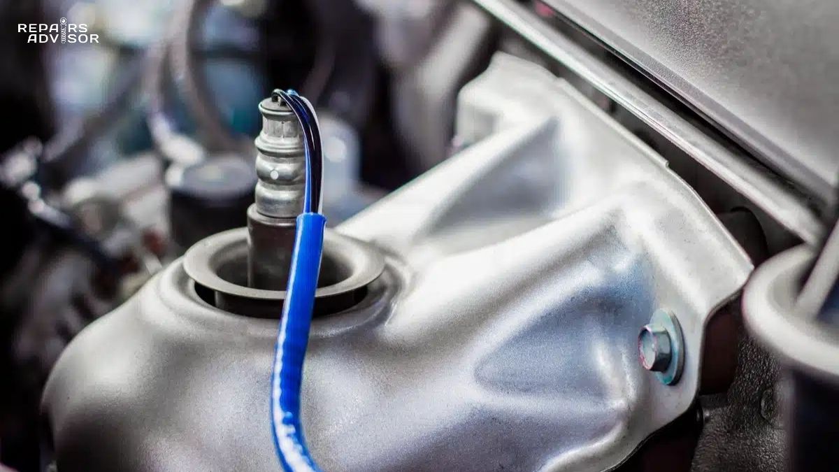
On most engines, you’ll find the PCV valve mounted in the valve cover, typically toward the rear of the engine. The valve usually sits in a grommet or threaded boss and connects to the intake manifold via a rubber or plastic hose. Look for a small cylindrical component about 3-4 inches long with hose connections on each end—this is your PCV valve.
Four-cylinder engines typically mount the PCV valve on the driver’s side valve cover near the firewall. The location takes advantage of the shortest path to the intake manifold while keeping the valve accessible for service. On these engines, you can often reach the valve from above with no disassembly required beyond removing any engine cover present.
V6 and V8 engines present more variation in PCV valve location. Many V-configuration engines use a single PCV valve mounted in one valve cover—usually the driver’s side—with the opposite cover featuring the breather system. Some designs place the valve in the valley between cylinder banks, requiring removal of the intake manifold for access. Before starting work, consult manufacturer-specific repair procedures for your vehicle’s exact configuration.
Transverse-mounted engines in front-wheel-drive vehicles often position the PCV valve at the back of the engine near the firewall. This location makes sense from an engineering standpoint but can create access challenges. On some models, you’ll need to work from underneath the vehicle or remove components like intake piping or the throttle body to reach the valve.
Breather System Location
The fresh air breather is typically located on the opposite valve cover from the PCV valve, though configurations vary. Look for a hose connection on the valve cover that runs to the air intake system, usually connecting somewhere between the air filter and throttle body. On some engines, the breather connects to a dedicated port on the intake manifold or throttle body.
Turbocharged and supercharged engines require special attention to breather system location because positive pressure from forced induction affects how the system operates. These engines often incorporate oil separators inline with the breather system, which may be mounted on the engine block, firewall, or integrated into the intake plumbing. When working on forced induction vehicles, identifying all components of the breather system is essential for proper diagnosis.
PCV Hose Routing
The hose connecting the PCV valve to the intake manifold follows various paths depending on engine layout. On most vehicles, this hose is 3/8 to 1/2 inch in diameter and runs from the valve cover to a dedicated port on the intake manifold. The routing typically avoids heat sources and moving parts while maintaining the shortest practical path.
Some engines use hard plastic tubes or formed metal lines for part of the PCV routing, with flexible hose sections at each end. These rigid sections provide durability and prevent hose collapse, but they can also crack over time—particularly on vehicles in cold climates where thermal cycling is severe. Inspect the entire route carefully, not just the flexible portions.
On engines with complex intake manifold designs, the PCV connection point may not be immediately visible. Some manufacturers integrate the PCV port underneath intake runners or hide it behind ancillary components. Understanding intake manifold design helps locate these hidden connections when service is required.
Access Procedures for Common Configurations
For straightforward PCV valve replacement on most four-cylinder and inline-six engines, the procedure is simple:
- Remove any plastic engine cover by unclipping or unbolting it
- Locate the PCV valve in the valve cover
- Disconnect the hose from the intake manifold end
- Pull or twist the valve out of its grommet in the valve cover
- Installation is the reverse, ensuring the grommet is in good condition
V6 and V8 engines may require additional steps depending on valve location. Some require removing intake components, ignition coil packs, or fuel system parts to access the PCV valve. Before beginning work, assess what’s in the way and whether you have the necessary tools and knowledge to remove those components safely.
For beginners uncertain about accessing their specific engine’s PCV system, starting with a visual inspection from above is wise. Use a flashlight to trace the hoses and identify all components before beginning disassembly. Take photos during the process to ensure correct reassembly, and never force connections—PCV components should come apart with reasonable effort when the correct technique is used.
Special Considerations for Specific Engine Types
Diesel engines often feature more complex crankcase ventilation systems due to higher blowby volumes. These systems may include multiple stages of oil separation, larger-diameter hoses, and check valves to prevent reverse flow. When working on diesel-specific systems, expect additional components and more involved access procedures.
Hybrid and electric vehicles with range-extending engines may have unique PCV system designs optimized for intermittent operation. These systems must function correctly despite the engine’s start-stop nature, which can affect how moisture and contaminants are managed. If you’re working on a hybrid vehicle, verify the specific PCV system design before assuming it matches conventional engine configurations.
High-performance and modified engines sometimes incorporate aftermarket PCV components like external oil separators, catch cans, or upgraded valves. When accessing these systems, understand that modifications may have changed the original routing or component locations. Always verify the current configuration before attempting service.
Safety Considerations and Professional Consultation
Working with the PCV system is generally safe for DIY enthusiasts with basic mechanical skills, but certain precautions and limitations apply:
For All Skill Levels:
- Always work on a cool engine to prevent burns from hot components
- Wear safety glasses when working around pressurized systems
- Have proper ventilation when working in enclosed spaces
- Dispose of old PCV valves and contaminated hoses properly
When to Seek Professional Help:
- If PCV valve replacement requires removing intake manifolds or other major components
- When symptoms persist after PCV system service, indicating possible internal engine damage
- If you encounter crankcase pressure exceeding normal levels (indicating serious engine problems)
- When working on turbocharged engines with complex oil separator systems
For Advanced DIY and Professional Mechanics:
- Use proper diagnostic procedures to verify PCV system function before replacement
- Understand that excessive blowby often indicates wear requiring professional engine evaluation
- Consider the entire crankcase ventilation system, not just the PCV valve, when diagnosing issues
- Reference manufacturer service procedures for torque specifications and special requirements
Remember that Repairs Advisor provides information for reference only—this content does not constitute a warranty on repair outcomes. Always consult manufacturer specifications and consider professional guidance for complex procedures or when you encounter unexpected conditions during service.
The PCV system represents elegant engineering simplicity, yet its importance to engine longevity and performance cannot be overstated. Regular inspection and timely replacement of PCV components form an essential part of preventive maintenance that pays dividends in reduced oil consumption, cleaner emissions, and extended engine life. Whether you’re a DIY enthusiast maintaining your daily driver or a professional mechanic diagnosing driveability concerns, understanding how this critical system functions enables better service decisions and improved vehicle performance.