Introduction: Why Oxygen Sensors Matter for Your Vehicle
Your vehicle’s oxygen sensor might be small, but it plays an outsized role in engine performance, fuel economy, and emissions control. This electronic component continuously measures the oxygen content in your exhaust gases and transmits real-time data to the engine control unit (ECU), enabling precise fuel mixture adjustments that keep your engine running efficiently.
The oxygen sensor—also called an O2 sensor or lambda sensor—became mandatory in U.S. vehicles starting in 1981 as part of stricter emissions regulations. Since then, oxygen sensor technology has evolved significantly. Modern vehicles typically feature multiple sensors positioned before and after the catalytic converter, working together to optimize combustion efficiency while monitoring emissions control system performance.
Understanding how oxygen sensors work helps you recognize failure symptoms early, prevent costly catalytic converter damage, and maintain optimal fuel economy. This guide covers oxygen sensor operation, common failure modes, diagnostic procedures, and replacement techniques for intermediate DIY mechanics and professional technicians alike.
Whether you’re troubleshooting a check engine light, experiencing decreased gas mileage, or preparing for emissions testing, knowing the role of oxygen sensors in your vehicle’s engine management system gives you the knowledge to address issues effectively and communicate confidently with repair professionals.
What Is an Oxygen Sensor and Why It’s Critical
Basic Function and Purpose
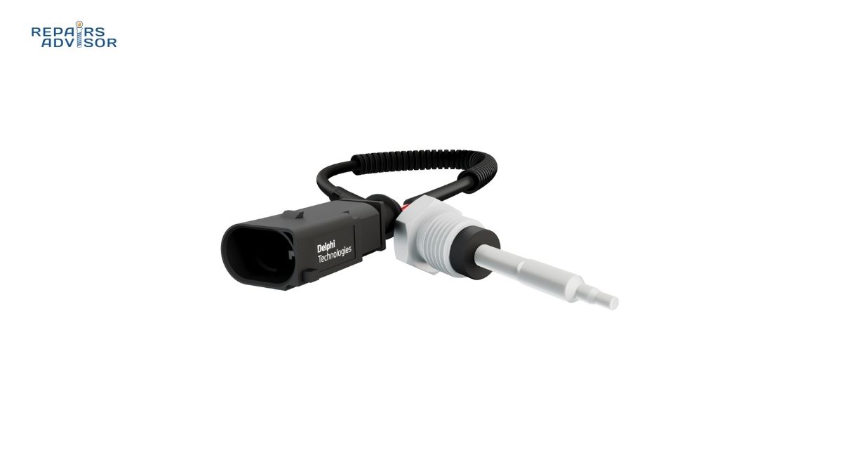
An oxygen sensor operates as your engine’s primary feedback mechanism for fuel delivery control. The sensor element sits directly in the exhaust stream, where it measures the amount of unburned oxygen present in the exhaust gases. This measurement is crucial because gasoline engines operate most efficiently at a specific air-to-fuel ratio of approximately 14.7 parts air to 1 part fuel—known as the stoichiometric ratio.
When this ratio deviates from the ideal, problems occur. A “rich” mixture contains too much fuel relative to air, resulting in incomplete combustion, wasted fuel, increased emissions, and potential catalytic converter damage from unburned fuel contamination. A “lean” mixture contains too much air relative to fuel, leading to elevated combustion temperatures, increased nitrogen oxide emissions, rough engine operation, and potential engine damage from overheating.
The oxygen sensor generates an electrical signal—either a voltage or resistance change depending on sensor type—that corresponds to the oxygen level detected. The ECU reads this signal continuously, comparing it against target values and adjusting fuel injector pulse width accordingly. This closed-loop control system makes hundreds of micro-adjustments per minute, maintaining the ideal air-fuel ratio across varying driving conditions, altitudes, temperatures, and engine loads.
Sensor Locations and Multiple Sensor Systems
Understanding oxygen sensor location terminology is essential for diagnosis and replacement. Professional technicians and diagnostic codes reference sensors by their position:
Upstream Sensors (Bank 1 Sensor 1, Bank 2 Sensor 1): These primary sensors mount in the exhaust manifold or immediately downstream from it, before the catalytic converter. Upstream sensors directly monitor exhaust gases leaving the combustion chambers and provide the critical feedback for real-time fuel delivery control. The ECU relies on upstream sensor data to operate in “closed loop” mode, constantly adjusting fuel mixture based on actual exhaust composition.
Downstream Sensors (Bank 1 Sensor 2, Bank 2 Sensor 2): These secondary sensors mount after the catalytic converter. Rather than controlling fuel delivery, downstream sensors monitor converter efficiency. A properly functioning catalytic converter removes most remaining oxygen from the exhaust stream, so downstream sensors should read relatively steady, low oxygen levels. If downstream readings begin mimicking upstream sensor oscillations, it indicates converter degradation.
Bank Configuration: On inline 4-cylinder or 6-cylinder engines with single exhaust systems, you’ll typically find two oxygen sensors total—one upstream and one downstream. V6 and V8 engines with dual exhaust manifolds (two cylinder banks) require four sensors—one upstream and one downstream for each bank. Some high-performance or emissions-focused vehicles use even more sensors for enhanced monitoring precision.
OBDII and Emissions Monitoring
The introduction of OBDII (On-Board Diagnostics, Second Generation) standards in 1996 revolutionized emissions monitoring. OBDII systems continuously compare upstream and downstream oxygen sensor readings to verify catalytic converter performance. The system monitors sensor response time, signal voltage ranges, switching frequency, and the oxygen differential between pre-cat and post-cat readings.
When the OBDII system detects oxygen sensor circuit malfunctions or implausible readings, it illuminates the check engine light and stores diagnostic trouble codes. Common oxygen sensor-related codes include the P0130-P0167 series for sensor circuit problems and the infamous P0420 code indicating catalyst system efficiency below threshold—often triggered by failing downstream sensors.
This comprehensive monitoring ensures vehicles maintain emissions compliance throughout their service life. However, it also means oxygen sensor failures trigger immediate check engine lights and can prevent passing state emissions inspections, making prompt diagnosis and repair essential.
How Oxygen Sensors Work: Technical Operation
Zirconia vs Titania Sensor Technology
Zirconia Sensors (Most Common Technology):
Zirconia oxygen sensors represent the most widespread technology, found in the majority of gasoline vehicles worldwide. The sensing element consists of a thimble-shaped ceramic cylinder made from zirconium dioxide (ZrO2), coated on both inner and outer surfaces with thin, porous layers of platinum that serve as electrodes.
The outer platinum layer is exposed directly to hot exhaust gases flowing past the sensor, while the inner layer faces a reference chamber vented to ambient atmospheric air. This dual-exposure design is fundamental to the sensor’s operation. At temperatures above 316°C (600°F), the zirconia ceramic becomes ionically conductive—oxygen ions can migrate through the crystal structure from the high-oxygen side to the low-oxygen side.
When exhaust oxygen content differs from atmospheric oxygen (approximately 21%), this oxygen concentration gradient causes voltage generation through the electrochemical process. Rich exhaust (low oxygen, high fuel content) creates a large voltage differential, typically 0.8-0.9 volts. Lean exhaust (high oxygen, low fuel content) creates minimal voltage differential, typically 0.1-0.2 volts. The ECU monitors this voltage and interprets readings above 0.45V as rich conditions requiring fuel reduction, and readings below 0.45V as lean conditions requiring fuel increase.
The porous platinum coating serves multiple purposes beyond electrical conduction. It acts as a catalyst, promoting oxidation of any remaining unburned hydrocarbons in the exhaust at the sensor surface, ensuring accurate oxygen measurement rather than measuring combustibles. The porosity allows exhaust gases to reach the zirconia element while providing structural stability.
Titania Sensors (Alternative Technology):
Titania sensors use a semiconducting titanium dioxide (TiO2) element whose electrical resistance varies dramatically with oxygen concentration. Unlike zirconia sensors that generate voltage, titania sensors require constant reference voltage from the ECU and return a resistance-modified signal.
The key advantage of titania sensors lies in their sealed construction. Because they don’t require atmospheric air reference, the sensor body can be completely sealed against moisture and contaminants. This makes titania sensors more durable in harsh environments but also more expensive to manufacture. Rich exhaust causes very low resistance (around 1,000 ohms), while lean exhaust causes high resistance (around 20,000 ohms or more).
Titania sensors also respond faster than zirconia sensors, reaching operating temperature more quickly and providing faster signal switching. However, their higher cost means they’re less common, typically appearing in specific vehicle applications where enhanced durability justifies the expense.
Wideband Sensors (Advanced Technology):
Introduced in the 1990s and becoming increasingly common, wideband sensors—technically called UEGO (Universal Exhaust Gas Oxygen) sensors—represent a significant technological advancement. Unlike narrowband zirconia sensors that simply indicate rich or lean conditions, wideband sensors precisely measure the actual air-fuel ratio across a broad range.
A wideband sensor incorporates both a zirconia sensing cell and an electrochemical oxygen pump cell. The ECU applies controlled current to the pump cell, either pumping oxygen ions into or out of a small measurement chamber to maintain a constant reference voltage in the sensing cell. The magnitude and direction of pump current required directly indicates the precise oxygen content and corresponding air-fuel ratio.
This design eliminates the rich-lean oscillation inherent to narrowband sensors. Instead of the ECU hunting for the stoichiometric point through constant over-correction, wideband sensors enable the ECU to set and maintain exact target air-fuel ratios. This proves particularly valuable during aggressive driving, cold starts, and catalyst warm-up periods when intentionally rich or lean mixtures optimize performance and emissions.
Heating Elements and Cold Start Performance
Oxygen sensors only function effectively at elevated temperatures. Unheated zirconia sensors, used in early emissions systems, required several minutes of engine operation before reaching the necessary 600°F+ operating temperature. During this warm-up period, the ECU operated in “open loop” mode—using predetermined fuel delivery tables without feedback correction. This resulted in higher emissions and reduced fuel economy during cold starts.
Modern heated oxygen sensors incorporate electric heating elements—resistance wires encased within the ceramic element—that bring the sensor to operating temperature within 20-30 seconds of engine start. The heater draws 1-3 amps from the vehicle electrical system, typically controlled by the ECU to maintain optimal sensor temperature across varying exhaust gas temperatures.
Heating element failures represent a common sensor failure mode. The heater circuit includes separate wiring from the signal circuit, and diagnostic codes differentiate between heater failures (P014x series codes) and sensor signal failures (P013x series codes). A failed heater causes extended open-loop operation, particularly noticeable as poor cold-start drivability and increased fuel consumption during the first few minutes of driving.
Signal Processing and ECU Integration
The ECU doesn’t simply react to oxygen sensor voltage—it analyzes signal characteristics to assess sensor health and optimize fuel control strategy. A healthy narrowband oxygen sensor switches between rich and lean readings 1-5 times per second during steady-state cruising, creating a characteristic oscillating waveform when viewed on a diagnostic scanner or oscilloscope.
The ECU monitors several signal parameters: switching frequency (how fast the sensor oscillates), amplitude (voltage range from rich to lean), and response time (how quickly voltage changes following throttle input). As sensors age, switching becomes slower, amplitude decreases, and response time degrades. The ECU compensates for gradual sensor degradation up to a point, but eventually sets diagnostic codes when performance falls outside acceptable parameters.
During initial cold start, the ECU operates in open loop, using coolant temperature, intake air temperature, and throttle position inputs to estimate required fuel delivery. Once the upstream oxygen sensor reaches operating temperature and begins switching normally, the ECU transitions to closed loop operation, using sensor feedback as the primary fuel control input. This transition typically occurs within 30-90 seconds depending on ambient temperature and driving conditions.
The system also employs adaptive learning, where long-term fuel trim values store learned adjustments in ECU memory. If the oxygen sensor consistently indicates lean conditions requiring 10% more fuel, the ECU eventually adopts this 10% increase as a baseline adjustment, allowing short-term fuel trims to handle immediate variations. Excessive fuel trim values (typically beyond ±10-15%) can indicate oxygen sensor problems, vacuum leaks, fuel delivery issues, or other system malfunctions.
Common Oxygen Sensor Failure Symptoms
Check Engine Light Illumination
The most obvious indicator of oxygen sensor problems is an illuminated check engine light accompanied by specific diagnostic trouble codes. Modern OBDII systems continuously monitor oxygen sensor performance and set codes when they detect out-of-range readings, slow response times, or circuit malfunctions.
Common oxygen sensor diagnostic codes include:
P0130-P0143 Series: Bank 1 sensor issues including circuit malfunction, slow response, no activity detected, high voltage, and low voltage for both sensor 1 and sensor 2
P0150-P0163 Series: Bank 2 sensor issues with the same fault categories as Bank 1
P0171-P0175 Series: System too lean or too rich conditions that often result from oxygen sensor failures providing incorrect feedback to the ECU
P0420-P0431 Series: Catalyst system efficiency below threshold, frequently caused by failed downstream sensors incorrectly reporting converter performance
A diagnostic scan tool reveals which specific sensor has failed and the nature of the problem. However, it’s important to remember that oxygen sensors report what they measure—a lean reading doesn’t necessarily mean the sensor itself has failed. The sensor might be accurately reporting a vacuum leak, failing fuel pump, or clogged fuel filter. Professional diagnosis distinguishes between faulty sensors and sensors correctly reporting other system problems.
Decreased Fuel Economy
One of the most costly symptoms of oxygen sensor failure manifests at the fuel pump. When an oxygen sensor degrades, particularly an upstream sensor controlling fuel delivery, it typically begins reading artificially lean. The ECU interprets these lean readings as insufficient fuel and compensates by increasing fuel injector pulse width.
This creates a vicious cycle: the failing sensor reports lean conditions, the ECU adds more fuel, the actual mixture becomes increasingly rich, but the degraded sensor can’t accurately detect the rich condition. Fuel economy drops noticeably—often 10-40% worse than normal. What once required fill-ups every 400 miles might suddenly need fuel every 250 miles.
The financial impact compounds over time. If a $300 oxygen sensor replacement restores 5 MPG on a vehicle driven 15,000 miles annually with $3.50/gallon fuel, the sensor pays for itself in saved fuel costs within just a few months. The longer you delay replacement, the more money you waste on excess fuel consumption.
Rich-running conditions from sensor failure also accelerate catalytic converter degradation. Unburned fuel entering the converter causes overheating and can damage the ceramic substrate or catalyst coating—a $1,000-2,500 repair compared to the relatively inexpensive sensor replacement.
Rough Idle and Engine Performance Issues
Oxygen sensor failures disrupt the precise fuel control required for smooth engine operation, causing various drivability problems:
Rough Idling: At idle, when airflow is minimal and fuel requirements are small, even slight fuel delivery errors become noticeable. A failing oxygen sensor can cause surging RPMs, irregular vibration, and unstable idle speed as the ECU unsuccessfully attempts to maintain stoichiometric mixture based on faulty sensor feedback.
Engine Hesitation: During acceleration, the engine needs rapid fuel delivery increases synchronized with increased airflow. A slow-responding oxygen sensor can’t keep pace with these dynamic conditions, causing hesitation or stumbling when you press the accelerator—particularly noticeable during moderate acceleration from steady speeds.
Misfiring: Severely incorrect air-fuel mixtures resulting from failed sensors can cause combustion misfires. Mixtures too rich may foul spark plugs, while mixtures too lean may not ignite reliably. Misfires feel like momentary power loss and often trigger additional diagnostic codes (P0300-P0308 series misfire codes).
Stalling: Complete engine shutdown can occur if sensor failure causes extreme lean conditions during low-speed maneuvering or deceleration. The engine receives insufficient fuel to maintain combustion and stalls, typically at stoplights or when coasting to a stop.
These performance symptoms not only affect driving comfort and safety but also indicate that the engine is operating outside optimal parameters—potentially causing accelerated wear on spark plugs, ignition coils, and cylinder components from improper combustion.
Failed Emissions Testing
Oxygen sensors are fundamental to emissions control systems, making sensor failures virtually guarantee emissions test failure. The connection between sensor health and emissions occurs through multiple mechanisms:
First, faulty sensors prevent the catalytic converter from operating in its optimal temperature and chemistry range. The converter requires exhaust gas composition within narrow parameters to achieve maximum reduction of carbon monoxide, hydrocarbons, and nitrogen oxides. When sensors provide incorrect feedback, the resulting rich or lean conditions push exhaust composition outside this optimal range.
Second, many states’ emissions testing programs include OBDII readiness monitors. These monitors track whether all emissions-related systems have completed their diagnostic self-checks. If oxygen sensor codes are present or have been recently cleared, the monitor shows “not ready,” and the vehicle automatically fails inspection.
Third, the actual tailpipe emissions measurements during testing will show elevated pollutant levels. Rich conditions from sensor failure increase carbon monoxide and hydrocarbon emissions. Lean conditions increase nitrogen oxide emissions. In some cases, emissions can be several times higher than legal limits.
States with mandatory annual emissions inspections require passing tests for vehicle registration renewal. Failed emissions tests mean you cannot legally operate the vehicle until repairs are completed and the vehicle is retested—making oxygen sensor replacement a priority when emission test deadlines approach.
Visual and Olfactory Indicators
Sometimes oxygen sensor failure announces itself through unmistakable signs even before the check engine light illuminates:
Black Exhaust Smoke: Rich fuel mixtures resulting from sensor failure cause visible black smoke from the tailpipe, particularly during acceleration or cold starts. This carbon-laden smoke indicates incomplete combustion and wasted fuel literally going up in smoke. The smoke often has a strong gasoline smell and may leave dark soot deposits on the rear bumper and around the tailpipe.
Sulfur Smell: The distinctive rotten egg odor of hydrogen sulfide gas often accompanies oxygen sensor problems. While catalytic converters normally convert sulfur compounds in gasoline into odorless sulfur dioxide, an overloaded converter receiving excessive unburned fuel from sensor-induced rich conditions can’t complete this conversion. The resulting hydrogen sulfide smell is unmistakable and indicates both sensor problems and likely converter stress.
Excessive Heat: Failed oxygen sensors causing rich mixtures force the catalytic converter to work overtime burning excess fuel. This can cause abnormal heat levels—the converter housing glowing red-hot in extreme cases or creating noticeable heat radiation under the vehicle. Excessive converter temperatures accelerate internal damage and can become a fire hazard if the vehicle is parked over dry grass or leaves.
Warning: Driving with known oxygen sensor failure risks expensive catalytic converter damage. A $200-500 sensor replacement becomes a $1,000-2,500 catalytic converter replacement if you ignore the problem. Address oxygen sensor failures promptly to prevent cascade failures in related emissions components.
Root Causes of Oxygen Sensor Failure
Age and Normal Wear
Like all vehicle components, oxygen sensors have finite service lives determined by exposure to extreme temperatures, thermal cycling, chemical exposure, and mechanical stress:
Unheated Sensors (Pre-1996 Vehicles): Early oxygen sensors without integrated heating elements typically lasted 30,000-50,000 miles before replacement. The lack of active temperature control meant these sensors operated at exhaust gas temperatures, experiencing extreme thermal stress during aggressive driving and gradual contamination during low-temperature operation.
Heated Sensors (1996+ Vehicles): Modern heated oxygen sensors generally last 60,000-100,000 miles, with some premium sensors exceeding 150,000 miles. The integrated heating element maintains consistent operating temperature, reducing thermal stress and minimizing contamination from low-temperature operation. However, heating elements themselves can fail, particularly from thermal shock during cold starts or water exposure.
Gradual Degradation: Even properly maintained sensors gradually lose sensitivity over time. The zirconia element slowly changes character through millions of thermal cycles. The platinum coating can become less catalytically active. Internal components experience fatigue. These gradual changes cause progressively slower sensor response until performance falls outside acceptable parameters and diagnostic codes set.
Age-related sensor failure typically manifests as slowly decreasing fuel economy and gradually diminishing engine responsiveness rather than sudden catastrophic failure. Proactive replacement at high mileage—particularly before emission testing deadlines—prevents inconvenient failures.
Contamination and Poisoning
External contamination represents the most common cause of premature oxygen sensor failure. Various substances can coat or chemically alter the sensing element, preventing accurate oxygen measurement:
Oil Contamination:
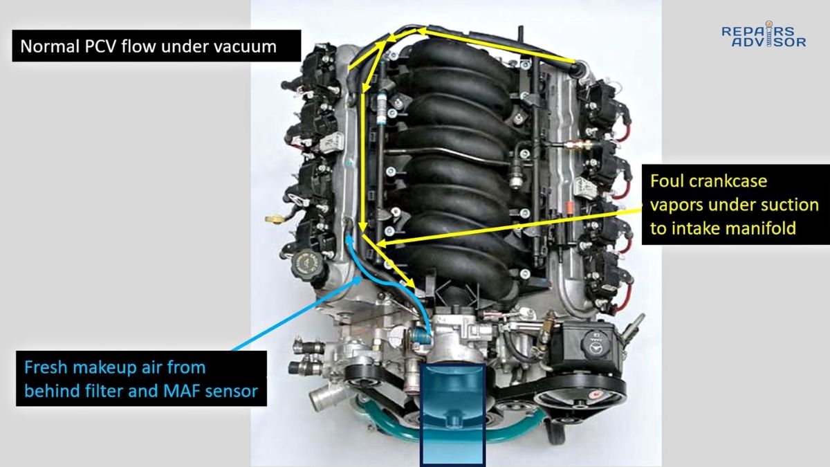
Engine oil entering the exhaust system spells rapid death for oxygen sensors. Oil reaches exhaust through several failure modes: worn piston rings allowing combustion chamber oil consumption, failed valve stem seals, turbocharger seal failures, or positive crankcase ventilation system malfunctions allowing excessive oil vapor into the intake.
The problem extends beyond just oil coating the sensor. Modern motor oils contain detergent and anti-wear additives with zinc, phosphorus, and other metallic compounds. These additives permanently poison the catalyst coating on oxygen sensors, rendering them inactive. An oil-contaminated sensor typically shows tan or brown discoloration and reads artificially lean or produces slow, damped signal oscillations.
Addressing oil contamination requires fixing the root cause—repairing worn engine internals, replacing turbocharger seals, or correcting PCV system problems. Simply replacing the oxygen sensor without correcting oil consumption will result in rapid repeat sensor failure.
Coolant Contamination:
Antifreeze infiltration into the exhaust system occurs through serious engine failures: blown head gaskets, cracked cylinder heads, or warped/eroded cylinder head surfaces. When compression pressure or coolant pressure forces coolant past head gasket seals, ethylene glycol and corrosion inhibitors enter the combustion chamber and exhaust stream.
Coolant contamination creates distinctive white crusty deposits on oxygen sensors. These silicate-based deposits physically block exhaust gas access to the sensing element and chemically degrade the platinum catalyst. Coolant-contaminated sensors often produce no signal at all or very weak, erratic signals.
Like oil contamination, coolant reaching the exhaust indicates serious engine problems requiring immediate attention beyond sensor replacement. Head gasket failure risks catastrophic engine damage from overheating or oil-coolant mixing. Always investigate and repair the source of coolant contamination before installing new oxygen sensors.
Fuel Additives and Silicone:
While less common than oil or coolant contamination, chemical poisoning from improper materials can quickly destroy oxygen sensors. The primary culprit is silicone-based gasket sealer. When mechanics use automotive RTV silicone sealant on engine components, the acetic acid released during curing volatilizes into exhaust gases and deposits silicon compounds on oxygen sensors.
Silicone-poisoned sensors display characteristic white deposits similar to coolant contamination but typically without the crusty buildup. The silicone coating insulates the sensing element from exhaust gases, causing artificially lean readings or complete signal loss.
The solution requires using only sensor-safe, non-silicone gasket sealers on intake manifolds, exhaust manifolds, and valve covers. Many manufacturers specify no sealant at all on exhaust components, relying solely on gasket compression. Check repair manuals before applying any sealants.
Certain fuel additives, particularly those containing metallic detergents or octane boosters with manganese compounds (MMT), can also contaminate sensors. Using reformulated or non-top-tier gasoline occasionally saves pennies per gallon but risks expensive sensor damage.
Carbon Buildup:
Rich fuel mixtures cause carbon fouling—black, sooty deposits coating the sensor element. Unlike chemical poisoning, carbon fouling is often reversible in early stages through extended highway driving that heats the sensor hot enough to burn off deposits. However, severe carbon buildup permanently reduces sensor sensitivity.
Carbon fouling has numerous root causes: clogged or dirty air filters restricting airflow, leaking fuel injectors allowing excess fuel delivery, failed mass airflow sensors reporting incorrect air intake, or vacuum leaks disrupting fuel metering. Identifying and correcting these issues prevents repeat sensor failures.
Electrical Issues
Oxygen sensor failures don’t always originate in the sensor element itself—electrical problems in wiring, connectors, or the ECU can mimic sensor failures:
Damaged Wiring Harness: Oxygen sensor wiring faces harsh conditions—high heat from the exhaust system, potential damage from road debris or improper repairs, and exposure to corrosive road salts. Wires can chafe through insulation on sharp edges, exhaust heat can melt insulation, and physical damage can sever conductors. These problems cause open circuits, short circuits, or intermittent connections that set oxygen sensor codes even though the sensor itself functions properly.
Corroded Connectors: Oxygen sensor electrical connectors, while designed for harsh environments, can corrode from moisture intrusion, salt exposure, or contamination from oil leaks. Corrosion increases electrical resistance, attenuates sensor signals, or causes complete circuit opens. Connector problems often cause intermittent codes that appear and disappear with temperature changes or vibration as corrosion alternately makes and breaks electrical contact.
Heater Circuit Failure: The heating element circuit uses separate wiring and higher current than the signal circuit. Heater failures can result from open heating element resistance wires inside the sensor, blown fuses, failed relays, or ECU driver circuit problems. Diagnostic codes differentiate heater failures from signal circuit failures, and many sensors show heater circuit failure before the sensing element itself fails.
Before condemning an oxygen sensor based on diagnostic codes, inspect the wiring harness and connectors. Check for physical damage, test continuity, measure resistance, and verify proper connector engagement. Many apparent “sensor failures” are actually wiring problems that don’t require sensor replacement.
Diagnostic Testing Procedures
OBD-II Scanner Diagnosis
Modern diagnostic trouble codes provide detailed information about oxygen sensor problems, but code interpretation requires understanding what codes actually indicate:
Initial Code Reading: Connect an OBD-II scanner to the diagnostic port (usually under the dashboard near the steering column) and retrieve stored codes. Note whether codes are current (malfunction currently present) or pending (intermittent or one-time occurrence). Record all codes—oxygen sensor problems sometimes occur alongside related issues like EVAP system codes or catalyst efficiency codes.
Code Family Interpretation:
P0130-P0143 (Bank 1 Sensors): These codes specify sensor location and problem type. For example, P0131 indicates Bank 1 Sensor 1 (upstream) circuit low voltage, while P0137 indicates Bank 1 Sensor 2 (downstream) circuit low voltage. The specific code number pinpoints the exact sensor and failure mode.
P0150-P0163 (Bank 2 Sensors): Parallel codes for the second cylinder bank on V6/V8 engines.
P014x Series: Oxygen sensor heater circuit malfunctions, indicating heating element or heater control circuit problems rather than sensing element failures.
Live Data Stream Analysis: Beyond simply reading codes, professional diagnosis examines live sensor data. Navigate to the scanner’s live data or graphing function and monitor oxygen sensor voltage or waveform:
- Healthy upstream sensors should oscillate between approximately 0.1-0.9 volts at 1-5 times per second during steady-state cruising
- Downstream sensors should show relatively steady readings with minimal oscillation, typically 0.4-0.7 volts
- Slow switching (less than once per second) indicates sensor degradation
- Stuck readings (voltage doesn’t change) indicate failed sensors or circuit problems
- Readings outside the 0-1 volt range may indicate wiring problems
Fuel Trim Monitoring: Observe short-term and long-term fuel trim values while monitoring oxygen sensor data. Fuel trims indicate how much the ECU adjusts fuel delivery from the base programmed values:
- Short-term fuel trims respond to immediate conditions, changing rapidly as you drive
- Long-term fuel trims represent learned average adjustments over time
- Fuel trims around 0% (±3-5%) indicate the system is operating near design targets
- Positive fuel trims (+10% or higher) indicate the ECU is adding fuel to compensate for lean conditions
- Negative fuel trims (-10% or lower) indicate the ECU is reducing fuel to compensate for rich conditions
Excessive fuel trim values combined with abnormal oxygen sensor readings help distinguish sensor failures from other problems. A failing oxygen sensor reading artificially lean might cause high positive fuel trims as the ECU tries to compensate. However, high fuel trims with normal sensor operation suggest problems elsewhere—vacuum leaks, fuel delivery issues, or air metering problems.
Multimeter Testing Methods
Multimeter testing provides more detailed electrical diagnosis than scanner data alone, particularly valuable for confirming sensor failures before replacement:
Voltage Test (Narrowband Zirconia Sensors):
- Warm the engine to full operating temperature (at least 10 minutes of driving)
- Locate the oxygen sensor and identify the signal wire (consult wiring diagram—usually the dark colored wire in the harness)
- Carefully backprobe the signal wire connector with a sharp probe or sensor-safe backprobe tool, maintaining the electrical connection
- Set the multimeter to DC voltage, 2-volt or 20-volt scale
- Connect the multimeter positive lead to the signal wire probe and negative lead to good chassis ground
- Observe voltage with the engine idling: it should oscillate between 0.1-0.9 volts approximately 1-5 times per second
- Quickly snap the throttle open and closed while watching the voltage: it should rapidly respond, swinging from low voltage (lean during deceleration) to high voltage (rich during acceleration)
Interpreting Voltage Test Results:
- Steady voltage around 0.45V without oscillation indicates a dead sensor
- Slow oscillation (less than once per second) indicates degraded sensor response
- Voltage stuck at the high end (0.8-1.0V) may indicate rich conditions, contaminated sensor, or wiring short to voltage
- Voltage stuck at the low end (0-0.2V) may indicate lean conditions, contaminated sensor, or wiring short to ground
- Voltage readings above 1.0V or below 0V indicate wiring problems rather than sensor issues
Resistance Test (Heater Circuit):
- Turn off the engine and wait for it to cool enough to safely access the sensor
- Disconnect the oxygen sensor electrical connector
- Set the multimeter to resistance (ohms), typically 200-ohm scale
- Locate the heater circuit terminals in the connector (consult wiring diagram—these are separate from signal wires)
- Measure resistance across the heater terminals: specifications typically range from 5-6 ohms for most sensors
- No reading (infinite resistance) indicates an open heater circuit
- Very low reading (under 2 ohms) may indicate partial short circuit
Resistance specifications vary by sensor manufacturer and design, so always consult service information for the specific vehicle. Heater circuit resistance testing helps diagnose P014x series codes (heater malfunction) and determine if the sensor heating element has failed even when the sensing element still functions.
Visual Inspection
Physical examination often reveals oxygen sensor problems without electrical testing:
Sensor Condition Inspection:
- Locate the sensor (may require raising the vehicle safely on jack stands)
- Examine the sensor tip—the portion exposed to exhaust gases:
- Clean, grayish-white appearance indicates normal operation
- Black, sooty deposits indicate carbon fouling from rich mixtures
- White, chalky deposits suggest silicone poisoning or coolant contamination
- Tan or brown discoloration indicates oil contamination
- Melted or deformed ceramic indicates severe overheating
- Cracked ceramic or damaged threads indicate physical damage
- Inspect the wiring harness:
- Check for damaged insulation, particularly where wires contact hot exhaust components
- Look for chafed wires where harness touches sharp edges or moving parts
- Examine connector terminals for corrosion (green/white deposits), bent pins, or damaged seals
- Verify proper connector engagement—loose connections cause intermittent codes
- Check for exhaust leaks:
- Exhaust leaks upstream of oxygen sensors allow fresh air infiltration, causing artificially lean readings
- Look for black soot deposits around manifold gaskets, flange connections, or cracked components
- Listen for hissing sounds with the engine running
- Exhaust leaks can mimic oxygen sensor failures, causing the ECU to think the mixture is lean when it’s actually correct
Professional Consultation: Complex diagnostic scenarios warrant professional analysis. Intermittent sensor failures that don’t occur during testing, multiple simultaneous codes affecting several systems, wideband sensor diagnosis requiring specialized equipment, or unexplained sensor failures after recent replacement all benefit from professional diagnostic capability including oscilloscopes, exhaust gas analyzers, and comprehensive electrical testing.
Professionals can also distinguish between sensors accurately reporting other system problems (vacuum leaks, fuel system issues) and actual sensor failures—a distinction that prevents unnecessary sensor replacement and ensures root causes are addressed.
Oxygen Sensor Replacement Cost and Procedure
Cost Breakdown (2025 Estimates)
Understanding oxygen sensor replacement costs helps you budget appropriately and evaluate quotes from repair shops:
Professional Replacement Costs:
The total cost for professional oxygen sensor replacement typically ranges from $200-600 per sensor, broken down as follows:
Parts Cost: $100-300 per sensor, varying significantly based on vehicle make and model. Economy vehicles with standard sensors fall toward the lower end. European luxury vehicles, hybrids with wideband sensors, or vehicles requiring specialized sensors fall toward the upper end. Upstream sensors generally cost more than downstream sensors due to their more demanding operating environment and critical role in fuel control.
Labor Cost: $100-250 per sensor, representing 45 minutes to 2 hours of shop time. Labor costs vary by sensor accessibility. Easily accessible sensors in the exhaust manifold may take only 30-45 minutes to replace. Sensors located deep in the engine bay, behind heat shields, or requiring removal of other components can take 2+ hours. Labor rates vary by geographic region and shop type—dealerships typically charge $120-175 per hour, independent shops $80-120 per hour.
OEM vs Aftermarket Parts Decision:
OEM (Original Equipment Manufacturer) Sensors ($150-300): These sensors come from the same manufacturer that supplied sensors for the vehicle when new, guaranteed to meet exact specifications. OEM sensors offer perfect fit, proven reliability, and optimal performance. Dealerships stock OEM sensors, and they’re also available through online OEM parts suppliers at discounted prices.
Premium Aftermarket Sensors ($100-200): Major sensor manufacturers like NTK, NGK, Denso, and Bosch produce aftermarket sensors meeting or exceeding OEM specifications. These sensors often match OEM quality at lower prices. Premium aftermarket represents the best value—significantly cheaper than OEM with comparable performance and reliability.
Budget Aftermarket Sensors ($50-100): Economy sensors from lesser-known manufacturers offer the lowest prices but come with risks. Build quality variations, less precise calibration, and shorter service life are common. Some budget sensors don’t properly communicate with certain vehicle ECUs, causing persistent check engine lights even when physically functional. Avoid sensors under $50—they’re almost always trouble.
DIY Replacement Costs:
Competent DIY mechanics can save 50-70% of professional replacement costs by purchasing parts and performing replacement themselves:
Parts Only: $50-300 depending on sensor quality chosen
Required Specialized Tools:
- Oxygen sensor socket ($10-25): These specialized sockets have slots to clear sensor wiring and come in both 7/8″ and 22mm sizes
- OBD-II scanner ($30-200): Essential for code clearing and verification
Optional but Helpful Tools:
- Sensor-safe anti-seize compound ($8-15)
- Quality penetrating oil ($8-12)
- Jack, jack stands, wheel chocks for safe vehicle access
Time Investment: 30-90 minutes depending on sensor location and your experience level. First-time replacements take longer as you familiarize yourself with the process. Difficult sensor locations in tight engine bays can extend replacement time considerably.
Step-by-Step Replacement Procedure
Safety Precautions:
Before beginning oxygen sensor replacement, prioritize safety:
- Work on a cool engine—exhaust components can cause severe burns for 30+ minutes after engine shutdown
- Use jack stands, never work under a vehicle supported only by a jack
- Disconnect the battery negative terminal to prevent electrical shorts
- Wear safety glasses to protect against falling debris when working underneath
- Use proper ventilation if working in a garage—exhaust fumes are dangerous
Required Information:
Identify the specific sensor to replace. Diagnostic codes specify bank and sensor position (Bank 1 Sensor 1, etc.). Consult the vehicle service manual or online resources to determine:
- Physical sensor location (may require accessing from above or below)
- Correct replacement part number
- Torque specifications
- Any special procedures or precautions
Replacement Steps:
Step 1: Locate the Sensor
Oxygen sensors mount directly into the exhaust system—either threaded into the exhaust manifold (upstream sensors) or into the exhaust pipe downstream of the catalytic converter. Some vehicles require removing heat shields or other components for access. Note the sensor wiring routing for installation of the new sensor.
Step 2: Apply Penetrating Oil
Exhaust system components corrode from heat, moisture, and road salt exposure. Oxygen sensors frequently seize in their threaded bungs, risking thread damage or sensor breakage during removal. Apply quality penetrating oil (PB Blaster, Liquid Wrench) to the sensor threads 15-20 minutes before attempted removal. For severely corroded sensors in high-mileage vehicles, apply penetrating oil the night before the repair and again immediately before removal.
Step 3: Disconnect the Electrical Connector
Oxygen sensor connectors typically use a locking tab mechanism. Press the release tab while pulling the connector halves apart. Some connectors are difficult to separate after years of heat exposure—avoid pulling on the wires. Instead, use a small flat screwdriver to carefully pry the connector apart while maintaining pressure on the release tab. If connector terminals are corroded, clean them with electrical contact cleaner before installation.
Step 4: Remove the Old Sensor
This critical step determines replacement success or the beginning of repair complications:
- Use the correct oxygen sensor socket—these specialized tools accommodate sensor wiring and prevent damage
- Position the socket squarely on the sensor hex to prevent rounding the hex
- If possible, use a long-handled ratchet or breaker bar for maximum leverage
- Turn counterclockwise with steady pressure—avoid jerking, which can break the sensor
- If the sensor won’t budge after reasonable effort, STOP—don’t force it
Step 5: Dealing with Seized Sensors
Seized sensors require careful handling. Excessive force breaks the sensor, leaving the threaded portion in the exhaust bung—a significant problem. If the sensor won’t turn:
- Apply more penetrating oil and wait 30-60 minutes
- Start the engine and run until the exhaust manifold is hot (not too hot to work near, but quite warm)—heat expansion helps break corrosion bonds
- Try removal again with the manifold warm
- As a last resort, use a propane or MAP gas torch to heat the bung (not the sensor) until it glows dull red—EXTREME CAUTION required, keep fire extinguisher nearby
- If the sensor breaks off, you’ll need a special extractor tool or professional help drilling out the broken sensor
Step 6: Inspect the Threaded Bung
With the old sensor removed, examine the threads in the exhaust manifold or pipe:
- Use a wire brush to remove rust and corrosion
- Check for damaged or crossed threads
- If threads are damaged, you may need a thread repair kit (tap and die) to restore the threads
- Ensure the sealing surface is clean and flat
Step 7: Prepare the New Sensor
Modern oxygen sensors come pre-coated with sensor-safe anti-seize on the threads. If your replacement sensor doesn’t have pre-applied anti-seize, apply a thin coating yourself:
- Use ONLY nickel-based or copper-free anti-seize compound
- Apply sparingly to the threads ONLY—avoid getting any compound on the sensor tip or electrical components
- Never use regular anti-seize containing copper or graphite, which can contaminate sensors
- Some manufacturers recommend no anti-seize on sensors with special thread coatings—check instructions
Step 8: Install the New Sensor
Thread the new sensor by hand to ensure proper engagement and prevent cross-threading:
- Start threading by hand—the sensor should turn easily for several full turns
- If you encounter resistance after just one or two turns, back out and restart—you’re cross-threading
- Once hand-tightened, use the oxygen sensor socket and ratchet to snug the sensor
- Do NOT overtighten—overtightening can damage the sensor or strip threads
- Torque to specification, typically 30-50 ft-lbs (consult service manual)
- If no torque specification is available, tighten firmly but not aggressively—the goal is secure mounting and exhaust sealing, not maximum tightness
Step 9: Reconnect the Electrical Connector
Plug the sensor electrical connector together, ensuring it clicks fully seated. Route the wiring following the original path, using any clips or ties to secure the harness away from hot exhaust components and moving parts. Ensure adequate slack in the wiring to prevent tension on the sensor connection—wires should drape naturally without stretching.
Step 10: Clear Diagnostic Codes and Verify Operation
- Reconnect the battery negative terminal
- Start the engine and verify no exhaust leaks at the sensor mounting location
- Connect the OBD-II scanner and clear stored diagnostic trouble codes
- Allow the engine to idle until it reaches operating temperature (coolant temperature above 180°F)
- Test drive the vehicle through varied conditions—city driving, highway cruising, acceleration, deceleration
- After the test drive, check for returned codes using the scanner
- Monitor the new sensor’s live data—it should show proper oscillation and response
Multiple Sensor Replacement Considerations:
Many professional technicians recommend replacing oxygen sensors in pairs—both upstream or both downstream sensors simultaneously, even if only one has failed. The reasoning:
- Sensors degrade at similar rates; if one failed, the other is likely near failure
- Mismatched old and new sensors can cause ECU inconsistency codes (some vehicles flag sensors with significantly different response characteristics)
- Labor cost savings—replacing both sensors at once avoids paying twice for similar labor
- Preventive replacement avoids near-term repeat repairs
However, this paired replacement recommendation is most relevant for high-mileage vehicles (over 100,000 miles) where both sensors have similar accumulated wear. For younger vehicles with isolated sensor failures, single sensor replacement is usually sufficient.
When to Seek Professional Help:
Some oxygen sensor replacement scenarios exceed typical DIY capabilities:
- Sensors in extremely difficult locations (behind turbos, deep in engine bays)
- Seized sensors that break during removal attempts—extracting broken sensors requires special tools
- Vehicles requiring component removal for sensor access (removing exhaust manifolds, etc.)
- Persistent codes after sensor replacement, indicating other system problems
- Wideband sensors requiring programming or adaptation procedures after replacement
Preventive Maintenance and Extending Sensor Life
Best Practices for Sensor Longevity
While oxygen sensors eventually wear out from normal use, several preventive measures significantly extend service life and prevent premature failure:
Use Quality Fuel:
Top-tier gasoline from major brands contains higher levels of detergent additives that keep fuel injectors and combustion chambers cleaner. Discount fuel may meet minimum regulatory standards but often lacks sufficient detergents, allowing deposits to form. These deposits can create rich-running conditions that carbon-foul oxygen sensors. The small per-gallon price premium for top-tier fuel provides insurance against fuel system and sensor problems.
Maintain Regular Oil Change Intervals:
Fresh, clean oil following manufacturer-recommended change intervals prevents oil consumption that contaminates sensors. Proper oil viscosity specification is equally important—using correct weight oil minimizes consumption. Extended oil change intervals or using incorrect oil grades increases oil consumption risk and shortens sensor life.
Address Leaks Promptly:
The moment you notice coolant consumption, oil consumption, or fluid leaks, investigate and repair them. Coolant entering the combustion chamber from head gasket failures, oil consumption from worn piston rings or valve seals, and vacuum leaks causing lean conditions all accelerate oxygen sensor degradation. Early intervention prevents cascade failures affecting oxygen sensors and catalytic converters.
Use Proper Gasket Sealers:
When performing engine repairs, use only sensor-safe, non-silicone gasket sealers. Many repairs don’t require sealant at all—compressed gaskets seal effectively without additional compounds. When sealant is necessary, choose products specifically labeled “oxygen sensor safe” and apply sparingly, keeping sealant away from exhaust ports.
Air Filter Maintenance:
Clogged or dirty air filters restrict airflow, causing rich fuel mixtures that carbon-foul oxygen sensors. Replace air filters at recommended intervals, typically every 15,000-30,000 miles depending on driving conditions. Dusty or dirty environments require more frequent replacement. The small cost of air filters prevents expensive sensor and fuel system problems.
Avoid Excessive Short Trips:
Repeated short trips prevent the engine and exhaust system from reaching full operating temperature. Incomplete combustion at low temperatures creates deposits that coat oxygen sensors. When possible, combine errands into longer trips, allowing the engine to warm completely. Extended highway driving periodically heats sensors hot enough to burn off minor deposits, keeping them clean.
When to Proactively Replace Sensors
Rather than waiting for sensor failure, consider preventive replacement in specific situations:
High-Mileage Vehicles: If your vehicle has 80,000-100,000 miles and original oxygen sensors, consider proactive replacement even without symptoms. The cost of planned replacement at your convenience is more manageable than emergency replacement when sensors fail before important trips or during busy periods.
Pre-Emissions Test Replacement: Many states require annual emissions testing for vehicle registration renewal. If your vehicle is near testing deadline and has high mileage or marginal sensor performance, replacing sensors before testing avoids failed test results, retesting fees, and registration delays.
Pre-Purchase for Used Vehicles: When buying a used vehicle, especially one at higher mileage, consider oxygen sensor testing and potential replacement as part of your purchase inspection. Sensor replacement on your schedule with your chosen parts is preferable to surprise failures shortly after purchase.
After Major Engine Repairs: Following repairs involving head gasket replacement, engine overhaul, or cooling system work where coolant may have contaminated the exhaust, inspect oxygen sensors carefully. Replace contaminated sensors immediately rather than waiting for gradual failure.
Professional Consultation for Persistent Issues
Sometimes oxygen sensor problems resist straightforward diagnosis and repair. If you experience:
- Repeated sensor failures shortly after replacement
- Persistent check engine lights with oxygen sensor codes after multiple sensor replacements
- Oxygen sensor codes accompanied by multiple other system codes
- Unexplained poor fuel economy despite new sensors
- Failed emissions tests despite sensor replacement
These scenarios suggest underlying problems beyond just sensor failure. Root causes might include:
- Vacuum leaks causing lean conditions that damage sensors
- Fuel system problems (weak fuel pump, failing injectors) causing rich or lean conditions
- Exhaust leaks affecting sensor readings
- ECU problems or wiring harness damage
- Internal engine problems (worn piston rings, valve guide wear) allowing oil consumption
Professional diagnosis using comprehensive testing—smoke machines for vacuum leak detection, fuel pressure testing, exhaust gas analysis, and electrical testing—identifies these underlying issues. Addressing root causes prevents repeated sensor replacement and ensures long-term reliable operation.
Conclusion: Maintaining Optimal Engine Performance Through Sensor Health
Oxygen sensors represent the critical feedback mechanism enabling modern engines to balance performance, fuel economy, and emissions control. These sophisticated sensors continuously measure exhaust oxygen content, providing the data your engine control unit needs to maintain ideal air-fuel ratios across constantly varying driving conditions.
Understanding oxygen sensor operation—from the electrochemical voltage generation in zirconia sensing elements to the ECU’s closed-loop fuel control algorithms—empowers you to recognize failure symptoms early and take appropriate action. The check engine light accompanied by P0130-series codes, noticeably decreased fuel economy, rough idle, or failed emissions tests all point toward oxygen sensor problems requiring prompt attention.
The relatively modest investment in oxygen sensor replacement—$200-500 on average—prevents cascade failures that multiply repair costs. A failing oxygen sensor not only wastes fuel costing hundreds of dollars annually but also risks catalytic converter damage requiring $1,000-2,500 replacement. The math strongly favors addressing sensor issues immediately upon detection.
For intermediate DIY mechanics, oxygen sensor replacement represents an achievable repair with appropriate tools and careful technique. The process involves accessing the sensor, removing the old sensor with proper procedures to avoid breakage, and installing the new sensor with correct torque and anti-seize application. Success requires patience—particularly with seized sensors—and attention to details like wiring routing and connector engagement.
However, diagnosis often proves more challenging than replacement. Distinguishing between sensors accurately reporting other system problems (vacuum leaks, fuel delivery issues) and actual sensor failures requires systematic testing with scanners and multimeters. Complex diagnostic scenarios benefit from professional expertise, ensuring root causes are identified rather than simply replacing sensors that might be functioning correctly.
Key Takeaways for Vehicle Owners:
- Oxygen sensors optimize fuel economy and reduce emissions by enabling closed-loop fuel control
- Modern vehicles use multiple sensors—upstream sensors control fuel delivery while downstream sensors monitor catalytic converter efficiency
- Common failure symptoms include check engine lights, decreased MPG (often 10-40%), rough idle, and failed emissions tests
- Sensor contamination from oil, coolant, or silicone compounds causes premature failure—address leaks and use proper repair materials
- Replacement costs $200-600 professionally, $50-300 for DIY with appropriate tools
- Preventive maintenance—quality fuel, regular oil changes, air filter replacement—extends sensor life significantly
When Professional Help is Warranted:
- Difficult sensor locations requiring extensive disassembly or specialized tools
- Seized sensors risking broken studs or exhaust manifold damage during removal
- Persistent diagnostic codes after sensor replacement suggesting underlying issues
- Wideband sensors requiring ECU adaptation procedures
- Complex diagnostic scenarios with multiple simultaneous system codes
By maintaining oxygen sensor health through preventive maintenance, addressing failure symptoms promptly, and performing replacements correctly, you ensure your vehicle delivers optimal fuel economy, reliable performance, and clean emissions throughout its service life. The oxygen sensor’s small size belies its critical importance—respect these sensors, monitor their condition, and replace them proactively for years of trouble-free driving.
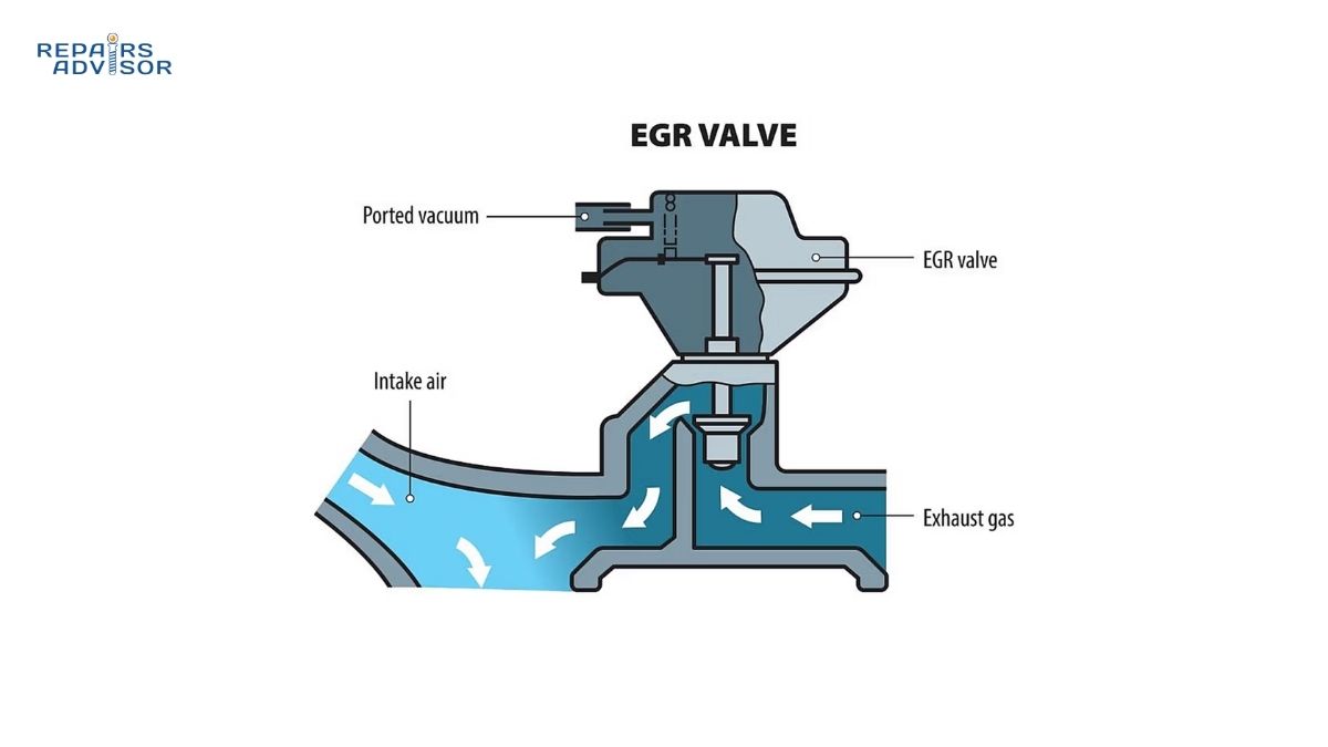
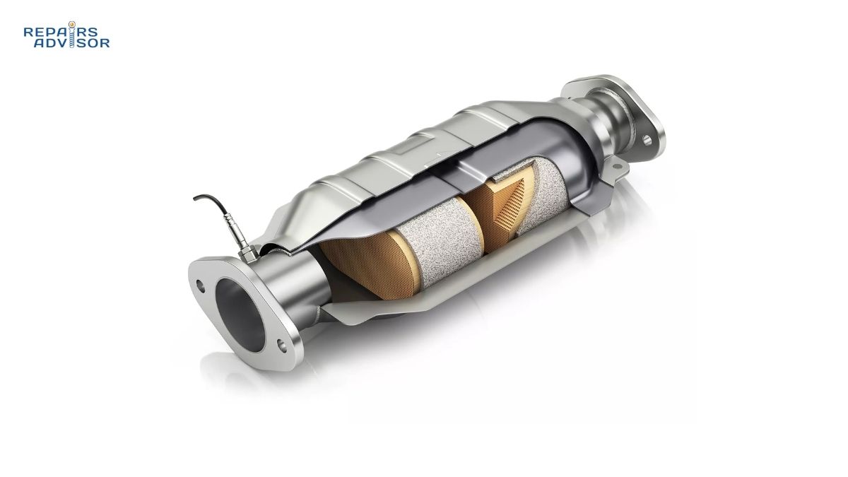
For more information about related emission control components, explore our guides on how catalytic converters work and EGR systems to understand the complete emissions control ecosystem in modern vehicles.