Information provided for reference only. Always consult manufacturer specifications and professional guidance for specific vehicle applications. Complex forced induction system diagnostics and modifications should be performed by qualified professionals.
Why Intercooler Is Critical for Engine Performance
The intercooler stands as a cornerstone component in modern forced induction systems, directly impacting engine power output, efficiency, and reliability. When turbochargers compress intake air to create boost pressure, this compression process generates significant heat that reduces air density and engine performance potential.
Performance Enhancement: Charge air cooling through intercooler systems increases air density by up to 25%, allowing more oxygen molecules per cubic inch to enter combustion chambers. This density improvement translates directly to increased power output from each combustion cycle, making intercoolers essential for maximizing turbocharger efficiency.
Thermal Protection: Hot compressed air from turbocharger compressor wheels can reach temperatures exceeding 300°F (149°C). Without proper charge air cooling, this heat creates knock-prone conditions, forcing engine management systems to retard timing and reduce boost pressure. The intercooler’s heat exchanger core removes this excess thermal energy, maintaining safe combustion chamber temperatures.
System Integration: Modern intercooler designs work seamlessly with variable geometry turbochargers and engine management systems to optimize boost efficiency across entire RPM ranges. Professional mechanics recognize intercooler efficiency as crucial for maintaining proper air-fuel ratios and preventing detonation damage.
Efficiency Maximization: Air-to-air intercooler systems achieve cooling efficiencies of 60-80%, significantly improving volumetric efficiency compared to non-intercooled forced induction systems. This boost efficiency enhancement allows smaller displacement engines to produce power levels previously requiring larger naturally aspirated configurations.
Intercooler Parts and Construction Explained
Heat Exchanger Core: The intercooler’s heat exchanger core forms the primary cooling element, constructed from aluminum tube-and-fin or bar-and-plate designs. Modern cores feature optimized fin density and tube geometry to maximize heat transfer surface area while minimizing pressure drop. Core construction varies from budget cast-aluminum designs to precision-welded performance units capable of handling extreme boost pressures.
End Tanks: Reinforced end tanks distribute incoming charge air across the entire core width, ensuring uniform airflow through all heat exchanger passages. Performance end tanks feature cast or fabricated aluminum construction with smooth internal contours to minimize turbulence. Tank design directly affects charge air cooling effectiveness, with larger tanks providing better air distribution but requiring more installation space.
Charge Pipes: High-strength charge pipes connect the intercooler to turbocharger outlet and throttle body inlet, handling boost pressures up to 30+ PSI in performance applications. Quality charge pipes feature mandrel-bent aluminum construction with precision-machined flanges and reinforced silicone couplers. Pipe routing affects both cooling efficiency and installation complexity.
Mounting Brackets: Robust mounting brackets secure the intercooler assembly while accommodating thermal expansion and vibration forces. Brackets must withstand aerodynamic loads at highway speeds while maintaining precise alignment with airflow passages. Performance mounting systems often feature adjustable elements for fine-tuning intercooler positioning.
Airflow Design: Internal core geometry incorporates advanced airflow design principles, including optimized fin patterns and tube configurations for maximum heat transfer. Sophisticated designs balance cooling effectiveness against pressure drop penalties, with performance units achieving superior charge air cooling while maintaining acceptable flow restrictions.
How Intercooler Works: Step-by-Step Operation
Step 1: Hot Charge Air Reception: Compressed air from the turbocharger compressor wheel enters the intercooler through the hot-side end tank at temperatures ranging from 200-400°F depending on boost pressure and ambient conditions. This superheated air contains reduced oxygen density due to thermal expansion, limiting combustion potential.
Step 2: Heat Exchange Process: As charge air flows through the heat exchanger core passages, aluminum fins and tubes conduct thermal energy from the hot air to the cooler ambient air flowing across the external core surfaces. The air-to-air intercooler design relies on vehicle forward motion and cooling fans to provide adequate airflow across the core for effective heat removal.
Step 3: Cooled Air Distribution: Cooled charge air exits through the cold-side end tank at temperatures typically 50-150°F cooler than inlet conditions, depending on intercooler efficiency rating and operating conditions. This temperature reduction increases air density by 15-25%, allowing significantly more oxygen molecules to enter the combustion chambers through the intake manifold.
Step 4: Engine Management Integration: The engine management system monitors charge air temperature through intake air temperature sensors, adjusting fuel delivery and ignition timing to optimize combustion with the denser air charge. Effective charge air cooling allows higher boost pressures and more aggressive timing advance for maximum power output.
Real-Time Performance Optimization: Modern intercooler systems work continuously with variable boost control systems, maintaining optimal charge air cooling across varying engine loads and ambient temperatures. The efficiency rating of the intercooler directly affects the engine’s ability to safely utilize higher boost pressures for enhanced performance.
Intercooler Location and Access Guide
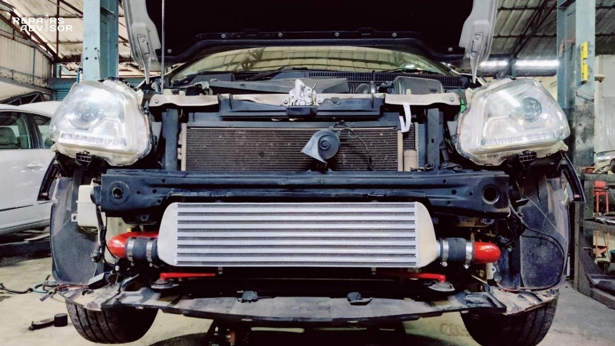
Front-Mount Installation: Most performance and heavy-duty applications utilize front-mount intercooler positioning, locating the heat exchanger core behind the front bumper for maximum ambient airflow exposure. Front-mount systems provide superior charge air cooling but require custom charge pipes and may affect radiator airflow. Access requires front bumper removal for core servicing.
Top-Mount Configuration: Subaru and other manufacturers employ top-mount intercooler designs, positioning the core above the engine for shorter charge pipe routing. Top-mount systems offer easier access for maintenance but face heat soak challenges from engine bay temperatures. These systems typically feature hood scoops for improved airflow.
Side-Mount Applications: Some vehicles utilize side-mount intercooler positioning, placing cores in front wheel wells or behind side air dams. Side-mount configurations balance cooling effectiveness with packaging constraints but may face airflow limitations compared to front-mount designs.
Access Considerations for DIY Enthusiasts: Basic intercooler inspection and cleaning require removing charge pipes and checking core condition for debris or damage. More complex maintenance involving core replacement typically requires professional assistance due to precision alignment requirements and boost leak testing.
Professional Service Requirements: Intercooler efficiency testing, pressure drop measurements, and performance optimization require specialized equipment and expertise. Professional mechanics can perform flow bench testing and recommend core upgrades based on specific boost efficiency targets and installation constraints.
Safety Reminders: Working with forced induction systems requires understanding of boost pressures and proper torque specifications for charge pipe connections. Always verify boost leak testing after any intercooler service to ensure system integrity and prevent potential engine damage from lean air-fuel conditions.