The intake manifold serves as the critical air distribution system that delivers the precise air-fuel mixture required for optimal engine performance. Understanding how intake manifolds work empowers DIY enthusiasts to diagnose airflow issues, recognize performance symptoms, and make informed decisions about maintenance and upgrades while ensuring professionals can optimize efficiency and address complex variable geometry systems.
Safety Note: Working with intake manifolds involves removing components from a pressurized fuel system. Always depressurize the fuel system, disconnect the battery, and allow the engine to cool completely before beginning work. When intake manifold work involves removing major engine components, professional consultation is recommended for safety-critical procedures.
Why Intake Manifold Is Critical for Engine Performance
The intake manifold fundamentally determines how efficiently your engine breathes, directly impacting power output, fuel economy, and emissions performance. Modern intake manifolds utilize sophisticated air distribution engineering to optimize airflow velocity, mixture preparation, and volumetric efficiency across the entire RPM range.
For DIY Enthusiasts: The intake manifold connects your throttle body to each cylinder through individual runners, ensuring balanced air distribution. When this system develops leaks or blockages, you’ll notice rough idle, reduced power, and poor fuel economy – symptoms that often indicate intake manifold gasket failure or carbon buildup requiring systematic diagnosis.
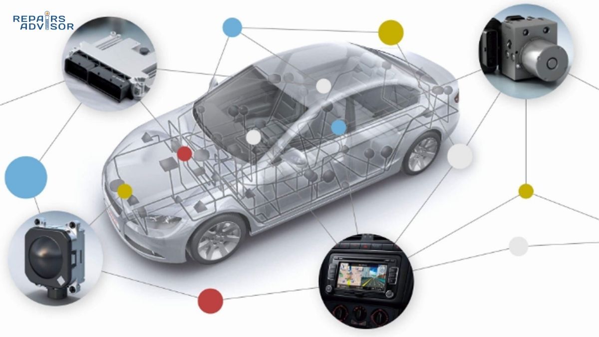
For Professional Mechanics: Advanced intake manifolds incorporate variable runner length systems, integrated charge motion control valves, and sophisticated plenum designs that require specialized diagnostic equipment to properly assess. Understanding the interaction between the intake manifold design and engine management systems is essential for optimizing performance and diagnosing complex driveability issues.
The intake manifold’s air distribution efficiency directly influences combustion quality, with poorly designed or damaged manifolds creating uneven cylinder filling that leads to performance variations, increased emissions, and accelerated engine wear. Modern variable geometry intake manifolds can increase torque by 15-20% across the operating range through optimized runner tuning.
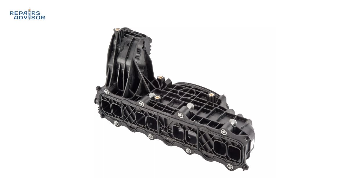
Intake Manifold Parts and Construction Explained
Understanding intake manifold construction enables accurate diagnosis of airflow problems and helps determine whether cleaning, gasket replacement, or complete manifold replacement provides the most effective solution for your specific application.
Plenum Chamber Design
The plenum serves as the central air distribution chamber that receives airflow from the throttle body and distributes it evenly to each runner. Modern plenums utilize carefully calculated volume and shape to minimize pressure fluctuations and ensure consistent air delivery. Larger plenums favor high-RPM power, while smaller designs improve low-end torque response.
Individual Runner Configuration
Each runner connects the plenum to specific intake ports, with length and diameter precisely tuned to optimize airflow velocity and create beneficial pressure wave effects. Variable-length runner systems use sliding sleeves or rotating valves to change effective runner length, optimizing volumetric efficiency across different engine speeds.
Professional Insight: Runner length tuning creates pressure wave resonance that can increase volumetric efficiency by 10-15% at specific RPM ranges. Short runners favor high-RPM breathing, while longer runners enhance low-RPM torque production through improved wave dynamics.
Gasket Sealing Systems
Intake manifold gaskets provide critical sealing between the manifold and cylinder head, preventing vacuum leaks that cause lean conditions and rough operation. Modern composite gaskets often include integrated coolant passages and require specific torque sequences to prevent distortion and ensure proper sealing.
Integrated Components
Modern intake manifolds often incorporate throttle body mounting surfaces, vacuum connections for accessories, and sometimes integrated charge cooling passages. Some designs include fuel rail mounting points and integrated temperature sensors for enhanced engine management precision.
How Intake Manifold Works: Step-by-Step Operation
The intake manifold orchestrates precise air distribution through carefully engineered fluid dynamics, creating the foundation for optimal combustion in each cylinder. This process involves complex pressure wave dynamics and airflow management that DIY enthusiasts can understand to improve diagnostic accuracy.
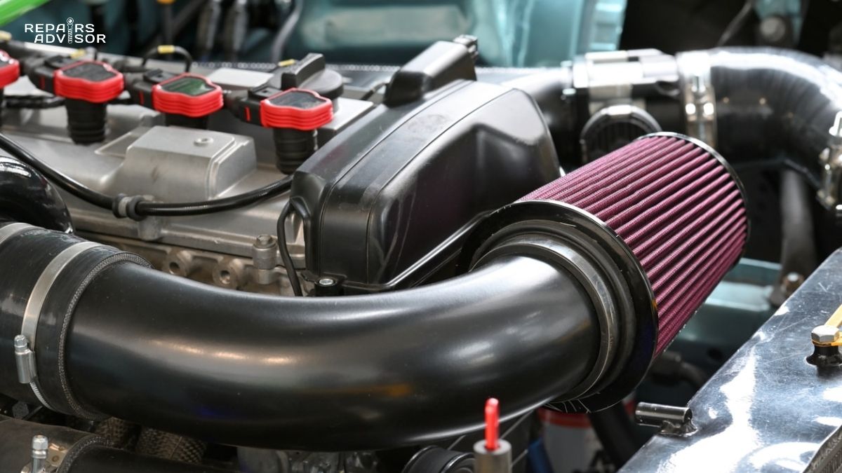
Air Entry and Initial Distribution
Air flows from the throttle body into the plenum chamber, where it undergoes initial pressure stabilization and distribution. The plenum volume and shape minimize pressure fluctuations caused by individual cylinder intake events, ensuring more consistent air delivery to each runner.
During this phase, air filters have already removed contaminants, and the throttle body has controlled overall airflow volume based on driver input and engine management demands. The plenum acts as a buffer, storing pressurized air that’s immediately available when intake valves open.
Runner Flow Dynamics
As each intake valve opens, air accelerates through the corresponding runner toward the cylinder. Runner design creates specific velocity profiles that enhance mixture preparation and combustion efficiency. Properly tuned runners generate pressure waves that actually help push additional air into the cylinder as the valve closes.
For DIY Diagnostics: Uneven idle or cylinder-specific misfires often indicate problems with individual runners, such as carbon buildup, vacuum leaks, or damaged runner walls. Each cylinder should receive equal airflow, so performance variations between cylinders typically trace back to runner-specific issues.
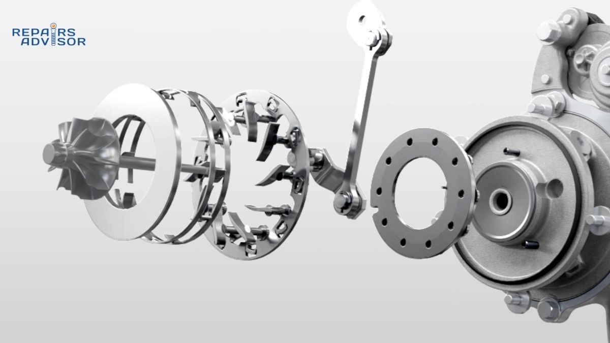
Variable Geometry Operation
Advanced intake manifolds adjust runner length or cross-sectional area based on engine operating conditions. Short runners provide unrestricted flow for high-RPM power, while longer configurations create beneficial pressure wave effects that enhance low-RPM torque production.
Professional Application: Variable geometry systems require integration with engine management systems to optimize switching points. Diagnostic procedures must verify both mechanical operation and electronic control system function to ensure proper performance across the operating range.
Pressure Wave Management
Intake manifold design utilizes pressure wave resonance to enhance volumetric efficiency. When properly tuned, returning pressure waves arrive at the intake valve just as it’s closing, creating a “supercharging” effect that increases cylinder filling without mechanical compression.
This wave tuning effect explains why intake manifold modifications can dramatically affect engine power characteristics. Changes to runner length, diameter, or plenum volume alter wave timing and can shift the torque curve significantly.
Intake Manifold Location and Access Guide
Locating and accessing the intake manifold requires understanding its central position in the engine bay and the various components that must be removed for service access. Proper access procedures prevent damage to surrounding systems while ensuring safe working conditions.
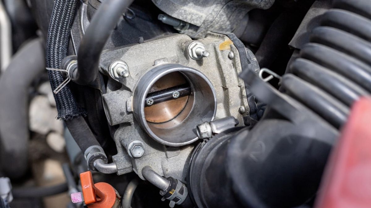
Physical Location and Identification
The intake manifold sits directly on top of the cylinder head, positioned between the throttle body and intake ports. On V-configuration engines, each bank typically has its own manifold, while inline engines use a single manifold spanning all cylinders.
Visual identification involves locating the large, often aluminum or plastic component that connects to multiple vacuum lines, the throttle body, and various engine sensors. The manifold will have individual connections leading to each cylinder’s intake port.
Access Requirements and Preparation
For Beginner DIY: Before attempting intake manifold work, ensure you have adequate tools, service manual procedures, and understand the fuel system depressurization process. Many intake manifold services require removing the air filter housing, throttle body, and various vacuum connections.
Safe access requires disconnecting the battery, depressurizing the fuel system, and allowing engine cooling. Mark all vacuum connections before removal to ensure proper reassembly. Digital photos of connection points prevent confusion during reassembly.
Component Removal Sequence
Typical access involves removing the engine cover, disconnecting the air filter housing and intake ducting, then carefully labeling and removing vacuum lines, electrical connections, and fuel system components as required.
Professional Considerations: Some vehicles require removing additional components such as the throttle body, fuel rails, or engine covers to access intake manifold mounting bolts. Always consult manufacturer procedures for specific torque requirements and sealing specifications.
Safety and Hazard Awareness
Working around the intake manifold involves potential exposure to fuel vapors, hot surfaces, and pressurized systems. Ensure adequate ventilation, have fire safety equipment available, and never work on intake systems with a hot engine.
Critical Safety Boundary: If intake manifold work requires removing fuel rails or involves direct fuel system access, this work requires professional-level expertise due to fire and safety hazards. DIY enthusiasts should limit work to external inspection, vacuum line replacement, and basic cleaning procedures.
Special Tool Requirements
Intake manifold service often requires specific tools including torque wrenches for precise bolt specifications, vacuum line removal tools to prevent damage, and sometimes special pullers for manifold removal. Professional work may require pressure testing equipment to verify proper sealing after service.
Modern variable geometry intake manifolds may require scan tools to verify electronic actuator operation and perform relearn procedures after service. Always verify tool requirements before beginning work to prevent project delays or component damage.
Repairs Advisor provides comprehensive technical information to support your automotive repair knowledge. This information is for reference only – always consult manufacturer specifications and professional guidance for safety-critical procedures. When intake manifold work involves fuel system access or requires special tools beyond basic hand tools, professional consultation ensures safe and effective completion.
For additional technical guidance, explore our engine management systems guide or visit our Ford repair manuals for manufacturer-specific procedures. Questions about specific procedures? Contact our support team at [email protected] for personalized assistance.