Why Exhaust Manifold Is Critical for Engine Performance
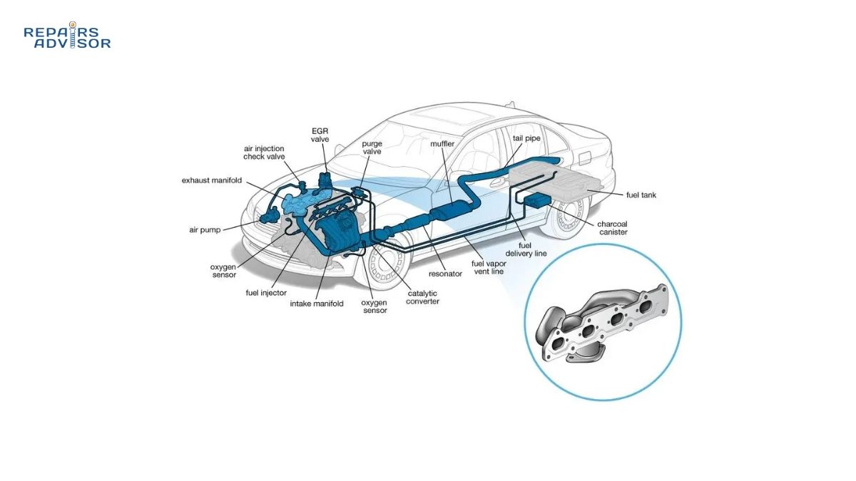
The exhaust manifold serves as the critical first component in your vehicle’s exhaust system, collecting hot combustion gases from individual engine cylinders and directing them into a single flow path. Without a properly functioning exhaust manifold, your engine would suffer from poor gas collection, reduced performance, and potential damage from exhaust backpressure. Understanding exhaust headers and their role in gas collection helps both DIY enthusiasts and professional mechanics diagnose problems and maintain optimal exhaust flow for maximum engine efficiency.
Modern exhaust manifolds are engineered to handle extreme temperatures exceeding 1,400°F while maintaining structural integrity and precise gas collection timing. The design directly impacts engine breathing, turbocharger performance (in forced induction applications), and overall exhaust flow characteristics that affect both power output and fuel economy.
Safety Note: Exhaust manifold work involves extremely hot components and potential exposure to harmful gases. Always allow the engine to cool completely before inspection, wear appropriate safety equipment, and consult professional mechanics for complex repairs involving welding or structural modifications.
Exhaust Manifold Gas Dynamics and Physics
Understanding Exhaust Pulse Behavior
When the exhaust valve opens, combustion gases don’t flow smoothly but create distinct exhaust pulse dynamics with three critical components that determine manifold performance:
High-Pressure Head: Created by the massive pressure differential between the combustion chamber (150-200 psi peak) and atmospheric pressure (14.7 psi). This initial blast travels at 1,500+ feet per second through the manifold runners, carrying the majority of exhaust energy and heat.
Medium-Pressure Body: The sustained flow as the piston completes its exhaust stroke, maintaining velocity while pressure gradually decreases. This component determines the bulk of exhaust gas evacuation and affects overall volumetric efficiency.
Low-Pressure Tail: The trailing component that creates vacuum effects downstream. As this low-pressure zone follows the main pulse, it generates the foundation for scavenging efficiency – the engine’s ability to naturally draw fresh air-fuel mixture while expelling spent gases.
These exhaust pulse dynamics follow fundamental gas laws – specifically the ideal gas law (PV=nRT) and combined gas law – where rapid pressure and temperature changes create the wave mechanics that drive manifold performance.
Advanced Scavenging Theory: Natural Supercharging
Pressure Wave Reflection and Rarefaction: As exhaust pulses travel through the manifold at supersonic speeds, they encounter geometry changes at the collector where pressure wave reflection occurs. The initial positive pressure wave reflects back as a rarefaction wave (negative pressure wave) that creates powerful vacuum effects.
Valve Overlap Timing: Modern engines use valve overlap – the brief period when both intake and exhaust valves are partially open simultaneously. When properly timed, returning rarefaction waves arrive during this overlap period, creating a vacuum that:
- Pulls remaining exhaust gases from the combustion chamber
- Helps draw fresh air-fuel mixture through the intake valve
- Increases volumetric efficiency by 10-15% in optimized systems
- Creates natural supercharging without mechanical assistance
Resonance Tuning for RPM Optimization: Manifold runners act as resonance chambers with length precisely calculated for target engine speeds. Primary tube length calculations determine scavenging effectiveness:
- Long runners (30-36 inches): Optimize scavenging at 2,000-4,000 RPM for peak torque
- Short runners (24-28 inches): Favor high-RPM breathing at 5,000-7,500 RPM for maximum horsepower
- Equal length principle: Performance headers maintain identical runner lengths to ensure synchronized pulse arrival at the collector
Exhaust Manifold Parts and Construction Explained
Primary Components and Assembly
Runners (Primary Tubes): Individual exhaust headers connect to each cylinder port, with internal diameter and length precisely calculated for optimal exhaust pulse dynamics and scavenging efficiency. Cast iron manifolds typically feature integrated runners with shorter lengths optimized for mid-range torque, while performance exhaust headers use separate tuned tubes with resonance tuning for specific RPM ranges.
Runner Diameter Optimization: The balance between scavenging effect and flow resistance requires precise sizing:
- Small diameter (1.5-1.75 inches): Strong scavenging effect and excellent low-end torque but limited high-RPM flow capacity
- Large diameter (1.875-2.0+ inches): Reduced scavenging strength but superior top-end breathing and backpressure optimization
Collector: Advanced Flow Convergence Engineering: The most complex aspect of manifold design where multiple high-velocity exhaust pulses converge without destructive interference. Modern collectors use stepped internal geometry – starting with the combined area of all primary runners, then tapering to the outlet diameter over 6-8 inches of length. This gradual transition maintains exhaust velocity while preventing reversion waves – negative pressure pulses that can travel back into cylinders during valve overlap, contaminating incoming fresh charge and reducing volumetric efficiency.
Heat Shields: Multi-layer protective barriers shield surrounding components from extreme exhaust temperatures, preventing heat-related damage to nearby wiring, fuel lines, and engine accessories. Heat shields also protect technicians during maintenance procedures.
Gaskets and Sealing: High-temperature gaskets create leak-proof connections between the manifold and cylinder head, while additional seals prevent exhaust gas escape at collector joints. Quality gasket materials include multi-layer steel, graphite composite, and specialized ceramic-fiber compounds.
Mounting Hardware: Heavy-duty studs, bolts, and brackets secure the manifold to the engine block, designed to withstand thermal expansion cycles and vibration stress. Mounting systems must accommodate thermal growth while maintaining proper alignment and sealing pressure.
Oxygen Sensor Ports: Threaded bosses accept oxygen sensors for emissions monitoring and fuel system feedback, positioned for accurate exhaust gas analysis. How Oxygen Sensors Work: Exhaust Analysis provides detailed information about sensor placement and operation.
Material Construction and Engineering
Cast iron exhaust manifolds offer excellent heat retention and durability for stock applications, while tubular steel exhaust headers provide improved gas collection and reduced weight for performance builds. Advanced materials include stainless steel for corrosion resistance and ceramic coatings for enhanced heat management.
The internal surface finish affects exhaust flow characteristics, with smooth-cast or machined surfaces reducing turbulence and improving gas collection efficiency compared to rough-cast alternatives.
How Exhaust Manifold Works: Step-by-Step Operation
Gas Collection Process
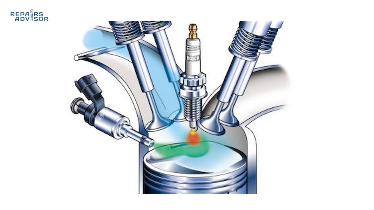
Step 1: Combustion Gas Capture: As each piston completes its exhaust stroke, hot combustion gases exit the cylinder through the exhaust valve and immediately enter the corresponding manifold runner. The timing and velocity of this gas collection process directly impacts engine breathing efficiency.
Step 2: Runner Flow Dynamics: Exhaust gases accelerate through the individual runners, with the runner length and diameter affecting gas velocity and scavenging effects. Proper exhaust headers are tuned to create beneficial pressure waves that assist in drawing gases from adjacent cylinders.
Step 3: Collector Merging: Multiple gas streams converge in the collector section, where careful design prevents flow interference between cylinders. The collector geometry manages the transition from multiple small-diameter flows to a single larger-diameter output.
Step 4: Downstream Delivery: The merged exhaust flow exits the manifold and enters the exhaust system for further treatment through How Catalytic Converters Work: Exhaust Treatment and sound control via How Mufflers and Resonators Work: Sound Control.
Performance Optimization and Gas Dynamics
Scavenging Effect: Advanced Gas Dynamics: As each exhaust pulse travels through the manifold at 1,500+ ft/sec, it creates a low-pressure tail that generates vacuum effects downstream. When these pressure waves hit the collector and reflect back as rarefaction waves, they return during valve overlap to create a powerful vacuum that pulls exhaust gases out while simultaneously helping draw fresh intake charge into the cylinder. This natural supercharging effect can increase volumetric efficiency by 10-15%, directly translating to measurable power gains. The magnitude of scavenging efficiency depends on precise runner length tuning – typically 28-32 inches for peak torque at 3,500 RPM, or 24-28 inches for high-RPM power optimization.
Resonance Tuning and Wave Dynamics: The manifold functions as a complex acoustic system where pressure wave reflection timing determines performance characteristics. Each runner acts as an organ pipe, with length calculated to ensure rarefaction waves return to the exhaust valve at optimal timing. Equal length headers maintain identical acoustic properties across all cylinders, preventing pulse interference that destroys scavenging effectiveness.
Backpressure Optimization: Contrary to common belief, exhaust systems don’t require backpressure for optimal performance. Instead, properly designed manifolds minimize restriction while maximizing exhaust pulse dynamics and scavenging effects. The goal is controlled pressure wave management rather than artificial flow restriction.
Temperature Management and Thermal Dynamics: The manifold’s thermal mass affects warm-up characteristics, exhaust pulse dynamics, and heat retention, directly impacting How Catalytic Converters Work: Exhaust Treatment efficiency during cold starts. Cast iron manifolds retain heat longer and maintain more consistent gas laws behavior, while steel headers heat up and cool down more quickly, affecting pressure wave reflection characteristics during temperature transitions.
Backpressure Control and Flow Management: The manifold design influences exhaust system resistance, which affects engine breathing, volumetric efficiency, fuel economy, and turbocharger operation in forced induction applications. Modern backpressure optimization focuses on maintaining optimal exhaust pulse dynamics rather than creating artificial restriction. How Turbochargers Work: Forced Induction for More Power explains the critical relationship between manifold scavenging efficiency and turbocharger spool characteristics.
Professional Insight: Monitor exhaust gas temperature (EGT) readings to assess manifold scavenging efficiency and detect potential issues such as restricted flow, excessive backpressure, or compromised resonance tuning that could indicate internal damage, blockages, or incorrect runner length specifications affecting volumetric efficiency.
Exhaust Manifold Location and Access Guide
Physical Location and Mounting
The exhaust manifold mounts directly to the cylinder head using a pattern of studs or bolts, positioned between the engine block and the exhaust system’s downstream components. Access varies significantly depending on engine configuration, vehicle design, and surrounding component packaging.
V-Engine Configurations: Typically feature separate exhaust manifolds for each cylinder bank, requiring different access procedures and tools for left and right side service. Bank 1 (containing cylinder #1) and Bank 2 manifolds may have dramatically different accessibility.
Inline Engine Layouts: Usually employ a single exhaust manifold serving all cylinders, mounted on either the front or rear side of the cylinder head depending on engine orientation and vehicle packaging requirements.
Access Procedures and Safety Considerations
Pre-Service Requirements: Always allow the engine to cool for at least 2 hours after operation before attempting exhaust manifold access. Exhaust components retain dangerous heat levels long after engine shutdown, and contact can cause severe burns.
Component Removal: Access often requires removing heat shields, air intake components, engine covers, or other surrounding parts. Document the removal sequence and hardware locations for proper reassembly. Ford Repair Manuals and other manufacturer-specific resources provide detailed disassembly procedures.
Safety Equipment: Use heat-resistant gloves, safety glasses, and ensure adequate ventilation when working around exhaust components. Be aware of potentially sharp edges on heat shields and manifold surfaces.
Tool Requirements: Exhaust manifold service typically requires metric or standard socket sets, universal joints for confined spaces, penetrating oil for corroded fasteners, and potentially specialized tools for broken stud extraction.
Common Access Challenges
Space Constraints: Modern engine bays often provide limited working room around exhaust manifolds, requiring creative tool positioning and sometimes partial component removal for adequate access. Professional mechanics use specialized low-profile tools and articulating ratchets for confined spaces.
Corroded Fasteners: Exhaust system hardware frequently suffers from corrosion due to heat cycling and moisture exposure. Apply penetrating oil well in advance of attempted removal, and be prepared for potential fastener breakage requiring extraction procedures.
Heat Shield Integration: Many vehicles integrate heat shields with other components or use complex mounting systems that require specific removal sequences. Improper heat shield removal can damage surrounding components or create reassembly difficulties.
Beginner Guidance: If you encounter broken or severely corroded exhaust manifold hardware, consult with a professional mechanic before attempting aggressive removal techniques that could damage the cylinder head or create more extensive repair requirements.
Inspection and Maintenance Points
Gasket Condition: Inspect manifold gaskets for signs of exhaust leaks, including black soot deposits, corroded mounting surfaces, or audible gas escape. Exhaust leaks can affect engine performance and create safety hazards in enclosed spaces.
Crack Detection: Examine cast iron manifolds for stress cracks, particularly around high-heat areas and mounting points. Small cracks can propagate over time and eventually cause complete manifold failure.
Hardware Integrity: Check mounting studs and bolts for corrosion, loosening, or damage. Loose exhaust manifolds create excessive stress on gaskets and can damage cylinder head surfaces.
For comprehensive exhaust system understanding, review How Exhaust Systems Work: Gas Flow, Backpressure & Sound Control to understand how manifold performance affects overall system operation. Additional emission control components like How Exhaust Gas Recirculation (EGR) Works: Emission Control also integrate with manifold design and operation.
Professional Consultation: For vehicles still under warranty or those requiring specialized tools for manifold removal, consult with certified technicians who have experience with your specific engine configuration. Complex repairs involving turbocharger integration or emission control systems may require dealer-level diagnostic equipment.
Disclaimer: This information is provided for educational purposes only. Exhaust manifold work involves high-temperature components and potentially hazardous gases. Always prioritize safety and consult qualified professionals for complex repairs. Repairs Advisor provides technical information only and does not warranty repair outcomes. For additional support with exhaust system documentation, visit our Help Center or contact [email protected].