Modern vehicles produce exhaust temperatures that regularly exceed 900°C—hot enough to melt aluminum and damage critical engine components. Without proper monitoring, this extreme heat can destroy turbochargers, catalytic converters, and diesel particulate filters, leading to repair bills that easily exceed $3,000. Exhaust gas temperature (EGT) sensors serve as the thermal guardians of your vehicle’s exhaust system, providing real-time temperature data that enables the engine control unit (ECU) to protect components and optimize emissions control.
Whether you’re a DIY enthusiast troubleshooting a check engine light or a professional technician diagnosing DPF regeneration problems, understanding how EGT sensors work is essential for modern vehicle repair. These small but critical sensors play a vital role in everything from turbocharger protection to diesel particulate filter regeneration, making them key players in both performance and emissions compliance.
In this comprehensive guide, we’ll explore the operating principles behind EGT sensors, the two main sensor types (NTC and PTC), strategic placement locations throughout the exhaust system, common failure causes and symptoms, diagnostic testing procedures, and replacement guidelines. By the end, you’ll have the knowledge needed to diagnose sensor failures and understand when professional service is necessary.
What Is an Exhaust Gas Temperature Sensor?
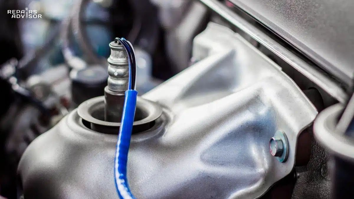
An exhaust gas temperature sensor is a thermistor-based device that measures the temperature of exhaust gases at strategic points throughout a vehicle’s exhaust system. The sensor converts thermal energy into an electrical voltage signal that the ECU uses for real-time thermal management and emissions control.
In gasoline engines, EGT sensors primarily protect expensive components from heat damage. When the sensor detects temperatures approaching dangerous levels, the ECU responds by reducing boost pressure in turbocharged applications or enriching the fuel mixture to lower exhaust temperatures. This protection is especially critical in modern downsized turbocharged engines that generate extreme heat from high-specific-output combustion.
Diesel engines rely heavily on EGT sensors for diesel particulate filter regeneration management. The DPF requires temperatures between 600°C and 700°C to burn off accumulated soot effectively. EGT sensors monitor temperature at the DPF inlet and outlet, providing the data necessary for the ECU to initiate, maintain, and confirm successful regeneration cycles. Without accurate temperature monitoring, regeneration cycles can fail, leading to DPF clogging and expensive filter replacement.
Modern vehicles commonly use three to five EGT sensors positioned at different locations throughout the exhaust system. This multi-sensor approach provides comprehensive thermal monitoring from the exhaust manifold through the tailpipe, enabling precise control of turbocharger operation, catalytic converter efficiency, DPF regeneration, and selective catalytic reduction (SCR) systems.
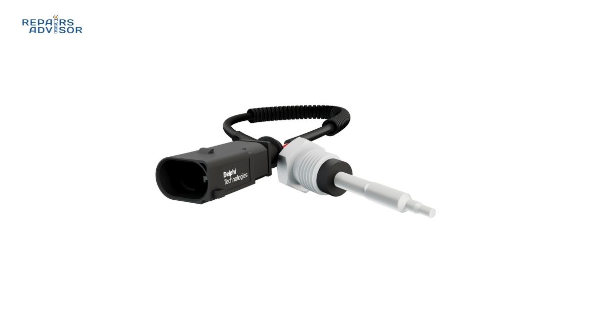
The sensor itself consists of a thermistor element housed in a stainless steel protective sheath designed to withstand extreme temperatures up to 900°C. The element is fixed in cement to protect against vibration damage, and the assembly threads directly into the exhaust system at predetermined measurement points. An electrical connector on the sensor’s cold end transmits the voltage signal to the ECU via the vehicle’s wiring harness.
Technical specifications vary by manufacturer, but most EGT sensors operate across a temperature range from -40°C to 900°C with response times measured in milliseconds. This rapid response enables the ECU to react quickly to thermal events that could damage components, making EGT sensors essential safety devices in modern exhaust systems.
How Exhaust Gas Temperature Sensors Work: Operating Principles
Thermistor Technology Basics
At the heart of every EGT sensor is a thermistor—a type of resistor whose electrical resistance changes predictably with temperature. This predictable relationship between temperature and resistance allows the ECU to calculate precise exhaust gas temperatures from the sensor’s electrical signal.
The sensor operates as part of a voltage divider circuit. Inside the ECU, a fixed resistor connects in series with the EGT sensor, and the ECU supplies a reference voltage (typically 5 volts) across this circuit. As exhaust temperature changes, the sensor’s resistance changes, which alters the voltage drop across the sensor. The ECU measures this voltage at the divider point and uses a calibration algorithm to convert it into a temperature reading.
This conversion relies on manufacturer-specific temperature-resistance curves programmed into the ECU during vehicle production. These calibration tables account for the non-linear relationship between temperature and resistance in most thermistor materials, ensuring accurate temperature measurement across the entire operating range.
For the beginner audience, think of this system like a smart thermometer. Just as a traditional thermometer uses mercury expansion to show temperature, an EGT sensor changes its electrical properties. The engine computer reads this electrical change and translates it back into a temperature number it can use to make decisions about engine operation.
The ECU continuously monitors the EGT signal and compares it against programmed limits. If temperatures exceed safe thresholds, the ECU can take protective action within milliseconds—reducing turbocharger boost pressure, enriching the fuel mixture to lower combustion temperatures, or in extreme cases, limiting engine power or shutting down the engine to prevent catastrophic damage.
Professional technicians should note that the signal conditioning circuitry within the ECU also compensates for ambient temperature effects and filters electrical noise from the ignition system and other sources. Modern ECUs also include diagnostic routines that monitor for open circuits (broken wires), short circuits (wires touching ground), and out-of-range values (sensor reading temperatures outside physically possible ranges).
Two Sensor Types: NTC vs PTC
Exhaust gas temperature sensors fall into two categories based on their temperature coefficient: negative temperature coefficient (NTC) and positive temperature coefficient (PTC). Understanding the difference is crucial for proper diagnosis and replacement.
NTC (Negative Temperature Coefficient) Sensors exhibit resistance that decreases as temperature increases. At room temperature (around 20°C), an NTC sensor might measure 25 kilohms (kΩ) to 6 megohms (MΩ), depending on its design. As exhaust temperature rises, this resistance drops dramatically—potentially to just a few hundred ohms at peak operating temperatures.
NTC sensors are typically found in entry-level applications and older vehicles. They’re less expensive to manufacture but have a highly non-linear temperature-resistance relationship, requiring more complex calibration curves. From a diagnostic perspective, NTC sensors have an advantage: when they fail in an open-circuit condition (wire break or internal element failure), the ECU immediately sees an out-of-range high resistance and sets a fault code.
PTC (Positive Temperature Coefficient) Sensors work oppositely—resistance increases as temperature increases. Most modern PTC sensors use platinum resistance thermometer technology (often designated as Pt200), with a characteristic resistance of 200 ohms at 0°C. The Pt200 designation indicates the sensor’s resistance at the reference temperature.
PTC sensors offer superior linearity across their operating range, meaning the resistance increases relatively proportionally with temperature. This linear relationship simplifies ECU calibration and improves measurement accuracy. Modern thin-film platinum sensors can maintain accuracy to within a few degrees across the entire -40°C to 900°C operating range.
However, PTC sensors present a diagnostic challenge that often frustrates technicians. When a PTC sensor begins to fail but hasn’t completely failed, it can continue transmitting plausible voltage signals to the ECU—but the readings are inaccurate. This can cause DPF regeneration problems without setting any fault codes, leading technicians to misdiagnose the issue as a failed DPF when the actual culprit is a drifting EGT sensor.
Replacement sensors must match the original sensor type. Installing an NTC sensor in place of a PTC sensor (or vice versa) will cause incorrect temperature readings because the ECU’s calibration tables won’t match the new sensor’s characteristics.
Strategic Sensor Placement
The location of EGT sensors throughout the exhaust system is carefully engineered to provide the data needed for specific control functions. Understanding these locations helps technicians identify which sensor has failed based on the symptoms and fault codes present.
Pre-Turbocharger (Exhaust Manifold) Location: This sensor measures raw combustion exhaust temperature before the turbocharger turbine. It provides the critical data needed to protect the turbocharger from thermal damage. When this sensor detects temperatures approaching the turbine wheel’s material limits (often around 950°C for steel turbine wheels), the ECU reduces boost pressure by opening the wastegate or adjusting variable geometry turbocharger vanes. This location experiences the highest temperatures in the exhaust system and sensors here typically fail first. Professional technicians should note that this sensor must not physically contact any part of the turbocharger housing, as metal-to-metal contact will cause false readings.
Post-Turbocharger Location: Positioned after the turbine wheel, this sensor monitors the temperature drop across the turbocharger. This data helps the ECU optimize boost control and can also indicate turbocharger efficiency. A failing turbocharger bearing or wastegate issue often shows up as abnormal temperature drops between the pre and post-turbo sensors.
DPF Inlet Sensor: Critical for diesel applications, this sensor tells the ECU when the DPF has reached the temperature necessary to initiate soot regeneration. It must read between 600°C and 700°C for effective regeneration. If this sensor fails, regeneration may not occur, leading to DPF clogging, or it may occur unnecessarily, wasting fuel and inconveniencing the driver.
DPF Outlet Sensor: Positioned after the particulate filter, this sensor confirms successful regeneration by monitoring temperature rise across the filter. During active regeneration, the outlet temperature should be higher than the inlet as soot burns. If the outlet temperature doesn’t rise appropriately, the ECU knows regeneration is incomplete and may extend the cycle or set a fault code.
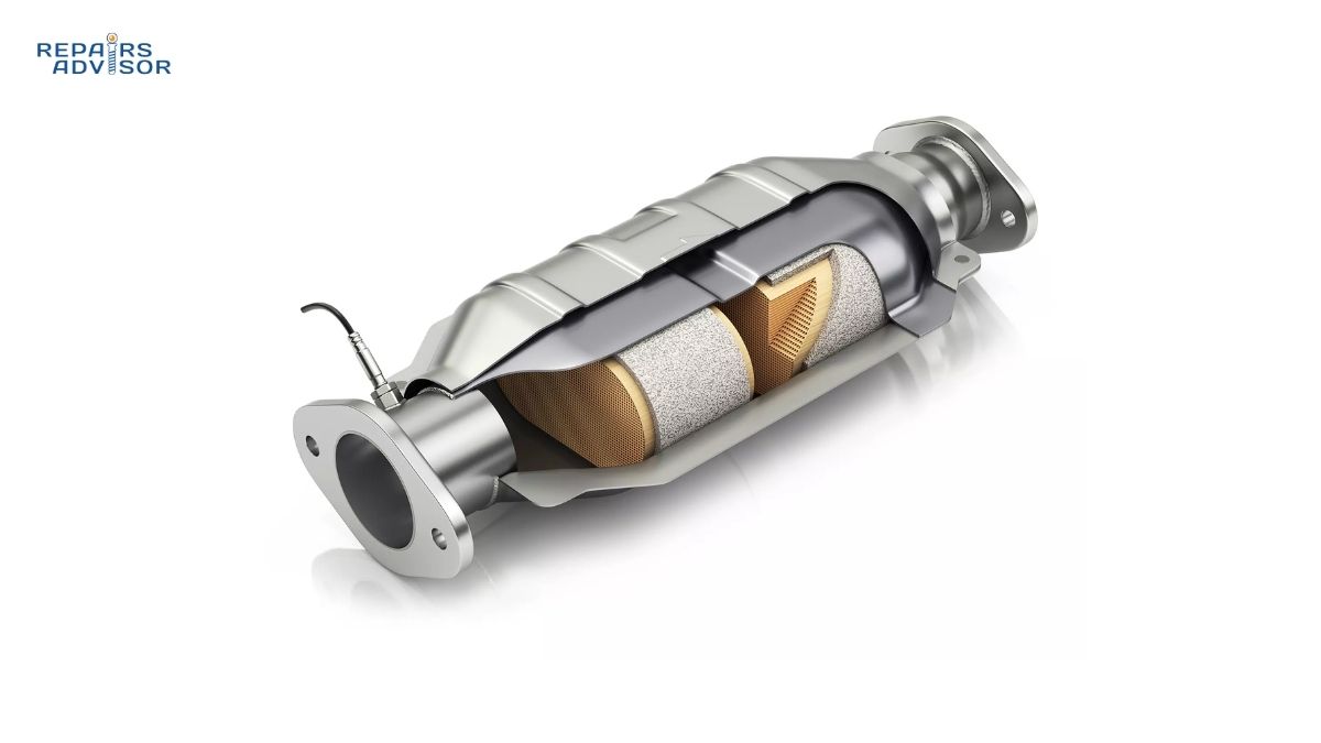
Catalytic Converter Monitoring: Sensors before and after the catalytic converter ensure the catalyst remains within its optimal operating temperature window (typically 400°C to 800°C). Too cold and the catalyst won’t effectively reduce emissions; too hot and the precious metal substrate can be damaged.
SCR System Sensors: In diesel vehicles equipped with selective catalytic reduction systems, EGT sensors monitor temperatures before and after the SCR catalyst to ensure optimal NOx reduction. The SCR catalyst requires minimum temperatures (typically 200°C to 250°C) to activate and too-high temperatures can damage the catalyst or cause unwanted ammonia slip.
Installation requires precise torque specifications—typically 40 to 45 Newton-meters (Nm) for most applications. Overtightening damages the internal thermistor element, while undertightening can allow exhaust leaks that contaminate the sensor reading with fresh air. Anti-seize compound should always be applied to the threads but must never contact the sensing element itself, as this can affect thermal response time.
Critical Functions: Why EGT Sensors Matter
Component Protection in Gasoline Engines
Modern gasoline engines, particularly turbocharged applications, generate significantly higher exhaust temperatures than their naturally aspirated predecessors. Downsized turbocharged engines commonly found in today’s vehicles produce power outputs that would have required much larger displacement engines just a decade ago. This performance comes at the cost of extreme thermal stress on exhaust components.
The pre-turbo EGT sensor serves as the primary guardian against turbocharger destruction. Turbine wheels made from steel alloy can withstand temperatures up to approximately 950°C, but exceeding this limit even briefly can cause material failure. The ECU uses real-time temperature data to modulate boost pressure through wastegate control or variable geometry adjustments, preventing thermal runaway conditions that would destroy the turbocharger.
Catalytic converters also require thermal protection. While catalysts need to reach their light-off temperature (around 400°C) to function effectively, temperatures above 900°C can cause the precious metal catalyst to sinter (fuse together), permanently reducing converter efficiency. When EGT sensors detect approaching overtemperature conditions, the ECU enriches the fuel mixture, using the extra fuel as a coolant to absorb heat and lower exhaust gas temperatures.
Engine components downstream of the combustion chamber also benefit from EGT monitoring. Exhaust valves, particularly in high-performance applications, can experience thermal fatigue and cracking when subjected to prolonged high-temperature operation. By limiting peak exhaust temperatures through fuel mixture and boost control, EGT sensors help extend valve life and prevent catastrophic valve failure.
DPF Regeneration Management in Diesel Engines
Diesel particulate filters trap soot from exhaust gases to meet emissions regulations, but this soot must be periodically burned off through regeneration. EGT sensors are absolutely critical to this process, and their failure is one of the most common causes of DPF problems.
Passive regeneration occurs during highway driving when exhaust temperatures naturally reach 600°C or higher. The DPF inlet sensor monitors temperature continuously, and when conditions are favorable, the trapped soot oxidizes spontaneously. However, vehicles used primarily for short trips may never reach temperatures sufficient for passive regeneration.
Active regeneration requires deliberate ECU intervention to raise exhaust temperatures. The ECU uses data from multiple EGT sensors to initiate and control this process. Strategies include post-combustion fuel injection (introducing fuel into the exhaust stream), late fuel injection timing (causing fuel to burn in the exhaust manifold), or intake throttling (reducing airflow to increase exhaust temperature).
The DPF inlet sensor must accurately read the temperature throughout the regeneration cycle. If the sensor reads low, the ECU may abort regeneration prematurely, leaving soot in the filter. If it reads high, the ECU may not initiate regeneration when needed, allowing soot to accumulate to dangerous levels. Professional technicians should note that a failed or drifting EGT sensor can cause DPF regeneration to take longer, occur more frequently, or fail completely—yet not set a diagnostic trouble code if the sensor failure is gradual.
The DPF outlet sensor confirms successful regeneration by detecting temperature rise across the filter as soot burns. A properly functioning DPF will show a temperature increase at the outlet during active regeneration. If this temperature rise doesn’t occur, the ECU knows regeneration has failed and may set a DPF efficiency code or prevent further regeneration attempts to avoid damaging the filter.
Incomplete or failed regenerations lead to progressive DPF clogging. As the filter fills with soot, exhaust backpressure increases, reducing engine power and fuel economy. Eventually, the DPF becomes so clogged that it requires professional cleaning or replacement—an expensive repair that often costs $1,500 to $3,000 or more.
Emissions Compliance
Modern emissions regulations require vehicles to meet strict standards not just in laboratory testing but under real-world driving conditions. EGT sensors play a crucial role in maintaining emissions compliance throughout the vehicle’s lifetime.
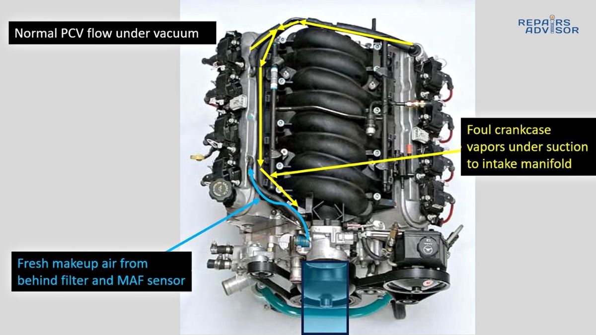
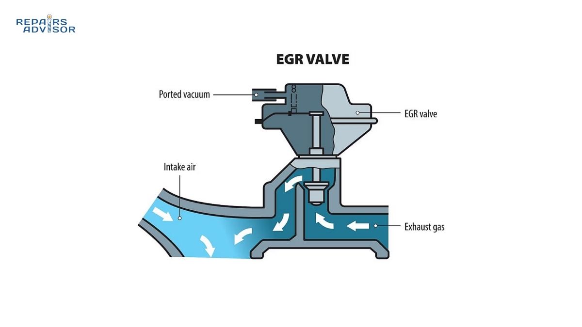
The exhaust gas recirculation (EGR) system relies on temperature monitoring to function effectively. EGR systems reduce nitrogen oxide (NOx) emissions by recirculating cooled exhaust gases back into the intake. The temperature of these gases must be carefully controlled—too hot and they increase combustion temperatures, actually increasing NOx production; too cold and combustion efficiency suffers.
EGT sensors monitor exhaust temperature at the EGR takeoff point and after the EGR cooler, providing the data needed to optimize EGR flow rates. When an EGT sensor fails in this portion of the system, EGR operation can become erratic without necessarily triggering the check engine light, resulting in emissions test failures that frustrate technicians and vehicle owners alike.
SCR systems use diesel exhaust fluid (DEF) to reduce NOx emissions, but the catalyst requires specific temperature ranges to function. Too cold and the catalyst doesn’t activate; too hot and ammonia slip occurs (unreacted ammonia passing through the exhaust). EGT sensors before and after the SCR catalyst enable the ECU to modulate DEF injection rates for optimal NOx reduction across all operating conditions.
Modern emissions regulations also include on-board diagnostics (OBD) requirements that mandate the detection of emissions system malfunctions. EGT sensors contribute to this diagnostic capability by providing data that helps the ECU detect failing catalytic converters, leaking exhaust systems, and ineffective DPF regeneration. Vehicles equipped with functioning EGT sensors can identify emissions problems before they become severe enough to cause visible smoke or failed emissions testing.
Common Failure Causes and Symptoms
Why EGT Sensors Fail
Understanding the failure mechanisms helps technicians prevent premature sensor failure and diagnose root causes that might damage replacement sensors.
Extreme temperature exposure ranks as the leading cause of EGT sensor failure. While sensors are designed to withstand temperatures up to 900°C, repeated thermal cycling and exposure to temperatures at the upper end of this range gradually degrades the thermistor element. Over time, the sensor’s resistance-temperature characteristics drift out of specification, causing inaccurate readings. In some cases, the thermistor element can crack or the internal connections can separate from thermal stress.
Diesel engines with fuel system problems present particularly harsh operating conditions for EGT sensors. Malfunctioning fuel injectors that cause incomplete combustion can expose sensors to unburned fuel and excessive soot, both of which accelerate sensor degradation. Similarly, engines with turbocharger failures that cause excessive exhaust temperatures can destroy EGT sensors in a matter of hours.
Severe vibration affects all wired sensors, and EGT sensors are no exception. The combination of heat and vibration can loosen internal solder joints or cause the lead wires to fatigue and break. This failure mode is especially common in diesel trucks used for heavy towing or off-road applications where vibration levels exceed those seen in passenger car service.
Wire damage during exhaust component replacement causes many premature sensor failures. EGT sensor wires run along or through the exhaust system where they’re vulnerable to damage from tools, hot surfaces, and physical contact with exhaust components. Technicians replacing exhaust manifolds, turbochargers, or DPF filters must carefully protect sensor wiring to prevent shorts, breaks, or insulation damage.
Even slight bending or twisting of EGT sensor wiring can cause microscopic cracks in the conductors that don’t fail immediately but create intermittent connections that produce baffling diagnostic issues. These intermittent failures often manifest as random check engine lights that clear themselves, making them extremely difficult to diagnose.
Fluid contamination from engine coolant leaks, oil consumption, or aftermarket fuel additives can coat the sensor element and alter its thermal response characteristics. The sensor may continue functioning but drift out of calibration, causing the ECU to make incorrect decisions about boost control, regeneration timing, or EGR flow rates. This drift happens gradually and may not set fault codes if the readings remain within the ECU’s plausibility limits.
Connector corrosion develops from the harsh environment under the vehicle. EGT sensor connectors are exposed to road salt, water spray, and temperature extremes that degrade the electrical contacts over time. Corroded connectors cause increased resistance in the signal circuit, making the ECU “see” incorrect temperatures. Professional technicians should always inspect connectors carefully during diagnosis and apply dielectric grease during reassembly to prevent future corrosion.
Carbon buildup on the sensor tip is common in diesel applications, particularly on DPF inlet and outlet sensors. While not technically a sensor failure, heavy carbon deposits insulate the sensing element from the exhaust gas stream, causing slow response times and inaccurate readings. Some sensor designs allow careful cleaning with appropriate solvents, but many manufacturers recommend replacement rather than cleaning due to the risk of damaging the thermistor element.
Installation errors cause many “premature” sensor failures. Overtightening the sensor during installation can crack the ceramic thermistor element or damage the internal connections. Undertightening allows exhaust leaks at the sensor threads, introducing cool air that skews temperature readings. Missing or incorrect application of anti-seize compound leads to sensor seizure in the threads, making future removal nearly impossible without breaking the sensor or damaging the exhaust port threads.
Diagnostic Fault Codes
Modern vehicles use a standardized set of diagnostic trouble codes (DTCs) for EGT sensor faults. Understanding these codes helps technicians quickly locate the problem sensor and determine the nature of the failure.
The most common P-codes for exhaust gas temperature sensors include:
- P0544, P0545, P0546: Bank 1, Sensor 1 circuit problems (open circuit, low voltage, high voltage)
- P0547, P0548, P0549: Bank 1, Sensor 2 circuit issues
- P2031, P2032, P2033: Bank 1, Sensor 3 circuit malfunctions
- P2034, P2035, P2036: Bank 1, Sensor 4 circuit faults
- P2080 through P2086: Various EGT sensor range/performance codes
- P247A: Particulate matter sensor temperature circuit malfunction
The sensor numbering system typically starts with sensor 1 at the front of the exhaust system (pre-turbo or exhaust manifold) and increases sequentially toward the rear. However, technicians should always consult vehicle-specific service information to confirm sensor locations, as numbering schemes vary between manufacturers.
Circuit codes (open, short to ground, short to voltage) usually indicate wiring problems rather than sensor element failure. These codes mean the ECU detected an electrical fault—no signal, shorted wiring, or incorrect voltage—rather than an out-of-range temperature reading.
Range/performance codes indicate the sensor is functioning electrically but providing readings that don’t make sense compared to other inputs. For example, if an EGT sensor reads 50°C while the engine is fully warmed up and the coolant temperature is 95°C, the ECU knows the EGT reading is implausible and sets a performance code.
One frustrating aspect of EGT sensor diagnosis is that PTC sensors can fail gradually without setting codes. If a sensor’s calibration drifts but the readings remain within the ECU’s acceptable range, no fault code triggers. This can cause DPF regeneration problems, reduced fuel economy, or performance issues without any warning light. Experienced technicians learn to compare live data from all EGT sensors simultaneously, looking for readings that don’t follow expected patterns even when no codes are present.
Symptoms of Sensor Failure
EGT sensor failures produce a range of symptoms that vary depending on which sensor has failed and how the ECU responds to the malfunction.
Check engine light illumination is the most common first indicator. When an EGT sensor circuit fails open or short, the ECU immediately recognizes the electrical fault and turns on the malfunction indicator lamp. However, the check engine light may not illuminate for gradual sensor drift or when PTC sensors fail in a way that produces plausible but incorrect readings.
Reduced fuel efficiency often accompanies EGT sensor problems in diesel applications. When the DPF inlet sensor provides inaccurate data, regeneration cycles may run longer than necessary or occur more frequently than needed. Each regeneration cycle consumes extra fuel—sometimes a gallon or more—so unnecessary or prolonged regenerations can increase fuel consumption by 10% to 15% or even more.
Unnecessary DPF regenerations frustrate drivers with frequent active regeneration cycles. The driver notices the engine running at higher idle speeds, coolant fans operating at maximum speed, and a distinctive “cooked soot” smell from the exhaust—all while the vehicle is parked or during light driving. If these regenerations occur daily or multiple times per week when they should only happen every few hundred miles, a faulty EGT sensor is a likely culprit.
Failed emissions testing can result from EGR system problems caused by faulty EGT sensors. The EGR temperature sensor monitors exhaust temperature for proper EGR operation, and its failure can cause the EGR system to malfunction without triggering obvious symptoms or setting fault codes. The vehicle may appear to run normally but fail emissions testing for excessive NOx output.
Vehicle enters limp mode in response to some EGT sensor failures, particularly in diesel trucks. Ford’s 6.7L Power Stroke diesel, for example, is notorious for entering limp mode (reduced power) when EGT sensors fail, as a protective measure against potential engine damage. Some vehicles even display a “pull over safely” message when the ECU interprets sensor data as indicating dangerous overheating conditions.
Engine shutdown occurs in some vehicle applications when the ECU believes exhaust temperatures have reached levels that could cause fire or catastrophic component failure. This is particularly common in applications where vehicles are equipped with automatic fire suppression systems or operate in environments where exhaust fires present serious risks.
Poor performance and reduced boost pressure affect turbocharged engines when the pre-turbo EGT sensor fails or reads high. The ECU interprets the high reading as indicating thermal stress and responds by reducing boost pressure to lower exhaust temperatures. Drivers notice reduced acceleration, power loss at highway speeds, and sluggish throttle response—symptoms that can be mistaken for turbocharger failure.
Excessive black smoke from diesel vehicles can indicate DPF regeneration problems stemming from faulty EGT sensors. When regeneration cycles don’t complete properly due to inaccurate temperature data, soot accumulates in the DPF. Eventually, the filter becomes so clogged that it can no longer trap particles effectively, and black smoke breaks through. At this point, the DPF typically requires professional cleaning or replacement.
For more information on related symptoms, see our guide on signs of a bad catalytic converter and signs of a bad EGR temperature sensor.
Diagnostic and Testing Procedures
Electronic Diagnosis
Modern EGT sensor diagnosis begins with a quality scan tool capable of displaying live data. Professional-grade tools provide the most comprehensive data access, but even basic OBD-II scanners can read fault codes and view limited sensor information.
Initial scan tool procedures:
- Connect the scan tool and retrieve all stored diagnostic trouble codes (DTCs) before clearing any codes or beginning repairs
- Record all freeze frame data associated with any EGT-related codes
- Check for related codes affecting the exhaust system, turbocharger, DPF, or EGR systems
- Note whether codes are current (failure is happening now) or pending/historical (failure occurred in the past but hasn’t reoccurred)
Live data comparison testing provides the most valuable diagnostic information. Access the scan tool’s live data function and locate all EGT sensor readings. With the engine completely cold (hasn’t run for several hours), all EGT sensors should read within a few degrees of each other and should closely match ambient air temperature. If one sensor reads significantly different—for example, three sensors show 20°C and one shows 45°C—the outlier sensor is likely faulty.
Start the engine and monitor the sensors as the engine warms up. All EGT sensors should show relatively smooth, simultaneous temperature increases. The pre-turbo sensor should show the highest temperatures, with downstream sensors reading progressively cooler. If one sensor remains at ambient temperature while others rise, or if one sensor shows erratic fluctuations while others remain steady, that sensor is suspect.
For diesel vehicles, observe EGT sensor behavior during a drive cycle that includes DPF regeneration. The DPF inlet sensor should rise to 600-700°C during active regeneration, while the outlet sensor should show similar or slightly higher temperatures. If regeneration occurs but the sensors don’t show appropriate temperature rise, or if temperatures seem unreasonably high or low compared to normal operation, sensor failure is likely.
Visual inspection checklist should always accompany electronic testing:
- Examine all visible sensor wiring for chafing, cuts, burns, or other damage
- Check electrical connectors for corrosion, bent pins, or physical damage
- Look for signs of exhaust leaks near sensors (black soot deposits on exterior surfaces)
- Verify sensors are properly torqued and not loose in their mounting ports
- Inspect nearby heat shields and insulation that protect sensor wiring
- Look for evidence of previous repairs (electrical tape, wire splices, replaced connectors)
Professional technicians should also verify that replacement sensors installed by previous repairs match the original equipment specifications. Incorrect sensor types (NTC installed where PTC is required, or vice versa) produce inaccurate readings but may not set fault codes if the readings remain within plausible ranges.
Multimeter Testing Procedures
Resistance testing with a digital multimeter provides definitive evidence of sensor element failure. However, technicians must know whether they’re testing an NTC or PTC sensor to interpret results correctly.
For NTC sensors:
- Disconnect the sensor’s electrical connector with the engine completely cold
- Set the multimeter to measure resistance (ohms)
- Connect the meter probes to the two sensor terminals (polarity doesn’t matter for resistance measurements)
- Record the resistance reading—typical values range from 25 kilohms to 6 megohms at room temperature, depending on sensor design
- Apply gentle heat to the sensor tip using a heat gun or hair dryer
- Watch the resistance reading—it should decrease smoothly as temperature rises
- If resistance doesn’t change with temperature, the sensor has failed
- Compare readings to manufacturer specifications if available
For PTC sensors:
- Follow the same disconnection and meter connection procedure
- At room temperature (approximately 20°C), expect readings between 200 and 300 ohms for most Pt200 sensors
- Apply heat to the sensor tip
- Resistance should increase linearly with temperature—a rough rule of thumb is approximately 0.8 ohms per degree Celsius for Pt200 sensors
- Verify the resistance changes smoothly without sudden jumps or erratic behavior
- Compare to manufacturer specifications when available
Reference voltage testing diagnoses ECU and wiring problems:
- Turn the ignition key to “on” position without starting the engine
- Disconnect the EGT sensor electrical connector
- Set the multimeter to measure DC voltage
- Connect the positive (red) probe to the reference voltage supply terminal at the connector on the vehicle side (not the sensor side)
- Connect the negative (black) probe to a good engine ground
- The meter should read 5.0 volts (±0.1 volts)
- If voltage is absent or significantly incorrect, trace the wiring back toward the ECU looking for breaks, shorts, or connector problems
The reference voltage test is particularly important because sensor elements rarely fail completely—most failures involve wiring, connectors, or ECU issues rather than the sensor itself.
Important note for multimeter testing: Many consumer-grade multimeters have maximum resistance ranges of 2 megohms. If testing an NTC sensor that should measure 6 megohms at room temperature, the meter will simply display “OL” (overload) or “1” indicating the resistance exceeds the meter’s range. This doesn’t mean the sensor is failed—it may just exceed the meter’s capability. Professional automotive multimeters typically measure up to 40 megohms, making them more suitable for EGT sensor testing.
Advanced Diagnostic Tools
Infrared temperature gun comparison testing provides real-world validation of sensor accuracy. This technique is especially valuable when live data shows plausible readings but you suspect sensor drift.
With the engine fully warmed up and running at normal operating temperature, use an infrared thermometer to measure the actual temperature of the exhaust pipe near each EGT sensor location. Point the IR gun at the exhaust pipe (not the sensor itself) about 2-3 inches from the sensor mounting point. Compare the IR gun reading to the scan tool’s live data for that sensor.
The readings won’t match exactly because the sensor measures gas temperature while the IR gun measures pipe surface temperature, but they should be reasonably close—within 50°C or so. If the sensor reads 400°C but the IR gun shows the pipe at 200°C, or vice versa, the sensor is suspect.
Caution: Exhaust pipes can exceed 300°C during normal operation. Maintain safe distances and never touch exhaust components with bare hands until the system has cooled completely.
Oscilloscope testing reveals signal quality problems invisible to standard scan tools. Connect the oscilloscope to the sensor signal wire and observe the voltage pattern as the engine operates through various load conditions. The signal should be smooth and stable, without electrical noise, sudden spikes, or dropouts. Erratic signals indicate damaged wiring, poor connections, or electrical interference from nearby components.
Forced regeneration observation provides valuable diagnostic data for diesel applications. Using a professional scan tool with bidirectional controls, initiate a forced DPF regeneration while monitoring all EGT sensor data. The sensors should respond quickly to temperature changes, show smooth increases to target regeneration temperatures, and maintain stable readings throughout the cycle.
If sensors respond sluggishly (taking minutes to register temperature changes that should happen in seconds), they may have carbon buildup insulating the sensing element. If readings fluctuate wildly during regeneration, the sensor may be failing intermittently. If temperatures never reach the expected regeneration range despite the engine clearly running hot, the sensor is reading low and should be replaced.
Replacement and Installation Guidelines
Replacing an exhaust gas temperature sensor is mechanically straightforward, but proper procedure is essential to ensure accurate readings and long sensor life.
Step-by-Step Replacement Procedure
Safety preparation (Critical):
- Allow the exhaust system to cool completely—minimum 1 hour after engine shutdown, preferably several hours
- Exhaust components can retain dangerous heat levels that cause severe burns
- Test suspect areas by carefully holding your hand near (not touching) the component—if you feel significant heat radiating, wait longer
- Wear heat-resistant gloves rated for high-temperature work even when the system feels cool
Battery disconnect:
- Remove the negative battery terminal to prevent electrical issues during sensor replacement
- This step prevents accidental short circuits if tools contact the sensor connector while connected
- Some vehicles require special procedures before battery disconnection to preserve memory settings—consult service information
Access the sensor:
- Most EGT sensors are located underneath the vehicle requiring jack stands or a lift for safe access
- Pre-turbo sensors in the exhaust manifold may be accessible from the engine compartment
- DPF sensors typically require removing exhaust shields or underbody panels
- Have a clear workspace around the sensor with room to maneuver tools
Disconnect the electrical connector:
- Carefully release the connector locking tab—these are often brittle from heat exposure
- If the connector is stuck or corroded, spray with penetrating oil and allow it to soak rather than forcing it
- Note the wire routing and any clips or brackets securing the harness—you’ll need to replicate this during reinstallation
- Inspect the connector for corrosion, damaged pins, or melted plastic
Remove the old sensor:
- Use the appropriate wrench size (typically 22mm hex) to avoid rounding the sensor hex
- Turn the sensor counterclockwise
- If the sensor is seized in the threads, do not force it—excessive force can strip the threads in the exhaust port
- For seized sensors, apply penetrating oil, allow it to soak overnight, then try again
- Severely seized sensors may require heat from a propane torch applied to the exhaust port (not the sensor) to break corrosion bonds
- If heat is required, exercise extreme caution near plastic components, wiring, and fuel lines
Inspect exhaust port threads:
- Once the old sensor is removed, inspect the threaded hole in the exhaust pipe or manifold
- Look for damaged threads, carbon buildup, or corrosion
- Clean threads carefully with a thread chaser or tap if necessary
- Do not use power tools for thread cleaning—hand tools provide better control and prevent oversize threads
Prepare the new sensor:
- Apply anti-seize compound to the sensor threads using a small brush or applicator
- Use high-temperature nickel-based anti-seize rated for exhaust applications
- Apply a thin, even coat covering all threads
- Critical: Keep anti-seize compound away from the sensor tip and sensing element—contamination can affect thermal response
- If anti-seize accidentally contacts the sensor element, clean it completely before installation
Install the new sensor:
- Thread the sensor by hand several turns to ensure it’s threading correctly
- Hand-tightening first prevents cross-threading and damaged threads
- Once hand-tight, use a torque wrench to tighten to manufacturer specifications
- Typical torque specification: 40-45 Nm (30-33 lb-ft), but always verify with vehicle-specific service information
- Never exceed specified torque—overtightening damages the internal sensor element
- Never undertighten—insufficient torque allows exhaust leaks and inaccurate readings
Reconnect the electrical connector:
- Clean connector terminals if any corrosion is present
- Apply dielectric grease to the connector terminals to prevent future corrosion
- Push the connector together firmly until the locking tab clicks
- Verify the connection is secure by gently tugging on the connector
- Route the sensor wiring exactly as it was originally, securing it with all original clips and brackets
- Ensure wiring has adequate clearance from exhaust components and moving parts
Reconnect the battery:
- Reinstall the negative battery cable and tighten securely
- Some vehicles may require relearning procedures after battery disconnection—consult service information
Clear fault codes and test:
- Connect a scan tool and clear all stored DTCs
- Turn the ignition on (engine off) and verify the check engine light is off
- Start the engine and verify it runs normally without warning lights
- View live data and confirm the new sensor provides a reasonable temperature reading
- Take the vehicle for a test drive including highway speeds and varied load conditions
- After the test drive, recheck for fault codes—a properly installed sensor should not set any codes
Professional Service Considerations
While DIY replacement is certainly possible, certain situations demand professional expertise.
When to consult a professional mechanic:
Sensor seizure in exhaust port is extremely common, especially in diesel applications and on vehicles operated in salt belt regions. Seized sensors require specialized extraction techniques including applying heat to the exhaust port while being careful not to damage nearby components, using special extractor tools that grip the sensor from the outside, or in worst cases, drilling out the failed sensor and repairing the exhaust port threads. These procedures require experience and specialized tools not typically available to DIY mechanics.
Multiple simultaneous sensor failures indicate underlying engine problems rather than coincidental sensor failures. When two or more EGT sensors fail within a short time period, the root cause must be diagnosed and corrected or replacement sensors will fail quickly. Possible causes include turbocharger failure causing excessive exhaust temperatures, fuel injector problems creating unburned fuel in the exhaust, or exhaust system leaks introducing contaminants. Professional diagnostic expertise is needed to identify and correct these underlying issues.
Persistent fault codes after replacement suggest the new sensor isn’t the problem. Possibilities include damaged wiring harness, corroded connections, ECU faults, or incorrect sensor specifications. Professional technicians have access to wiring diagrams, technical service bulletins, and diagnostic procedures needed to trace electrical faults through the vehicle’s complex wiring systems.
DPF regeneration problems continuing after sensor replacement indicate more complex issues with the DPF system. The particulate filter may be damaged or clogged beyond regeneration, requiring professional cleaning or replacement. The DPF pressure sensor system may have faults. Or the engine may have underlying problems causing excessive soot production. Professional diagnosis using specialized scan tools can identify these issues.
Programming or adaptation requirements affect some vehicles. Certain manufacturers require new EGT sensors to be programmed or adapted to the vehicle’s ECU using dealer-level diagnostic equipment. Without this programming step, the new sensor may not function correctly even though it’s properly installed. This is especially common in European vehicles from manufacturers like Volkswagen, Audi, Mercedes-Benz, and BMW.
Estimated costs for professional service:
- Part cost: $50-$300 depending on vehicle make/model, sensor location, and OEM vs. aftermarket
- Labor time: 0.5-2.0 hours depending on sensor accessibility
- Labor rate: $75-$150 per hour varies by region and shop type (independent vs. dealer)
- Total typical range: $125-$550 for straightforward replacement
- Seized sensor extraction: Add $100-$300 if special procedures required
- Thread repair: Add $150-$400 if exhaust port threads damaged
For guidance on related diagnostic procedures, visit our comprehensive diagnostic codes section.
Maintenance and Prevention
Preventing premature EGT sensor failure saves money and reduces the risk of being stranded with a vehicle in limp mode or with a shutdown engine.
Preventive Maintenance Strategies
Regular visual inspections during routine maintenance catch problems before they become failures. Include EGT sensor connector inspection during every oil change. Look for corrosion on connector terminals, cracked connector bodies, or damaged wire insulation near the connectors. A few minutes of inspection can identify problems that would otherwise lead to unexpected failures.
Protection during exhaust repairs prevents the majority of “premature” sensor failures. When replacing turbochargers, exhaust manifolds, catalytic converters, or any other exhaust component, take extra care with sensor wiring. Use zip ties or clips to secure wiring away from work areas. Cover connectors with plastic bags to keep out debris. Handle sensors gently and never use them as leverage points or handles when working on nearby components.
Proper torque application during installation is absolutely critical. Invest in a quality torque wrench and use it every time you install an EGT sensor. The torque specification exists for a reason—it provides the precise clamping force needed to seal the sensor without damaging the thermistor element. Undertightening allows exhaust leaks; overtightening cracks the ceramic element. Both result in premature failure.
Anti-seize compound usage prevents future sensor seizure and makes replacement much easier years down the road. Always use high-temperature nickel-based anti-seize compound on sensor threads. This simple step that takes 30 seconds can save hours of frustration during the next replacement. Never skip this step, even on new vehicles—exhaust thread seizure can occur in as little as 20,000 miles in severe service conditions.
Address root causes promptly to prevent sensor damage. If your check engine light comes on for fuel injector codes, turbocharger codes, or EGR codes, address these problems quickly. A malfunctioning fuel injector that causes incomplete combustion can destroy EGT sensors in weeks through soot contamination and thermal shock. A failing turbocharger can expose sensors to temperatures beyond their design limits. Fixing these underlying problems protects sensors and prevents cascading failures.
Quality replacement parts make a significant difference in sensor longevity. OEM sensors are engineered specifically for your vehicle’s operating conditions and include the correct thermistor type with proper calibration. High-quality aftermarket sensors from reputable manufacturers can perform equally well at lower cost. However, bargain-basement sensors may use inferior materials, incorrect thermistor types, or poor construction that leads to early failure. When choosing between a $50 sensor and a $150 sensor for the same application, remember that the $50 sensor that fails after 20,000 miles is actually more expensive than the $150 sensor that lasts 100,000 miles.
Replacement Interval
Unlike spark plugs, air filters, or other regular maintenance items, EGT sensors have no predetermined replacement interval. Replace them only when they fail or during extensive exhaust system repairs where sensor removal is necessary.
In properly functioning engines with normal operating conditions, EGT sensors typically last 100,000 kilometers (about 62,000 miles) or more. Many sensors continue functioning reliably for the entire vehicle lifetime. However, severe service conditions, frequent trailer towing, racing applications, or engines with underlying problems can dramatically shorten sensor life.
Diesel Engine Specific Maintenance
Diesel vehicles with DPF systems place extra demands on EGT sensors, requiring additional preventive measures.
Proper DPF maintenance reduces sensor stress and extends sensor life. Keep the DPF system functioning correctly by addressing regeneration problems promptly. Ignore warnings about soot loading or regeneration needs at your peril—an overloaded DPF subjects sensors to extended periods of extreme temperature that accelerate failure.
Complete regeneration cycles whenever possible. If the vehicle initiates active regeneration (higher idle speed, cooling fans running at maximum), continue driving for 20-30 minutes to allow the cycle to complete. Parking the vehicle and shutting off the engine during regeneration interrupts the cycle and forces it to restart later, creating additional thermal stress on sensors.
Avoid short trips exclusively with diesel vehicles. Modern diesel engines equipped with DPF systems need regular highway driving to maintain system health. If your driving pattern consists primarily of short trips (less than 10 miles), the DPF never reaches temperatures sufficient for passive regeneration. This forces frequent active regeneration cycles that wear sensors prematurely. Consider occasional highway drives or using a lower DPF-equipped vehicle for short-trip duty.
Use high-quality diesel fuel from reputable stations. Low-quality fuel with high sulfur content produces more soot during combustion, leading to more frequent regeneration cycles and greater thermal stress on sensors. The slight additional cost of premium diesel fuel pays dividends in reduced maintenance costs and extended component life.
Conclusion
Exhaust gas temperature sensors serve as critical thermal guardians in modern vehicles, protecting expensive components from heat damage while enabling emissions control systems to function effectively. These small sensors monitor exhaust temperatures ranging from ambient to over 900°C, providing the real-time data that ECUs need to optimize turbocharger operation, manage DPF regeneration, and maintain emissions compliance.
Understanding the operating principles—whether NTC or PTC thermistor technology—helps diagnose sensor problems and select correct replacements. Strategic placement at multiple points throughout the exhaust system provides comprehensive thermal monitoring, with each sensor location serving specific control functions. Pre-turbo sensors protect turbochargers, DPF inlet/outlet sensors manage regeneration, and catalyst sensors optimize emissions control.
When EGT sensors fail, symptoms range from illuminated check engine lights to vehicle shutdown, depending on which sensor has failed and how the ECU responds. Common failure causes include extreme temperature exposure, vibration damage, wire damage during repairs, fluid contamination, and connector corrosion. Proper diagnosis requires combining scan tool data analysis, visual inspection, and multimeter resistance testing to differentiate between sensor element failures and wiring/connector problems.
Replacement procedures are mechanically straightforward but demand attention to critical details: proper cooling before beginning work, correct torque specifications, anti-seize compound application, and careful wire routing. While DIY replacement is certainly achievable for accessible sensors, seized sensors, multiple failures, or persistent problems often require professional expertise and specialized tools.
Preventive maintenance focusing on careful handling during exhaust repairs, proper installation torque, anti-seize usage, and addressing underlying engine problems significantly extends sensor life. Quality replacement parts and prompt attention to fault codes prevent cascading failures that damage multiple expensive components.
When Professional Help Is Needed
Consult a qualified technician when you encounter:
- Sensors seized in exhaust ports requiring extraction techniques
- Multiple sensors failing simultaneously (indicates underlying engine problems)
- Fault codes that persist after proper sensor replacement (wiring/ECU issues)
- DPF regeneration problems continuing despite new sensors
- Vehicles requiring dealer-level programming for sensor adaptation
- Uncertainty about proper sensor type or specifications
- Exhaust port thread damage requiring repair
- Complex diesel emissions system diagnostics
Professional mechanics have access to specialized tools, technical service bulletins, wiring diagrams, and experience with common failure patterns that enable efficient diagnosis and repair of complex EGT sensor issues.
Take Action
Exhaust gas temperature sensors are too important to ignore when problems develop. A $150 sensor replacement today prevents a $3,000 turbocharger failure tomorrow. If you’re experiencing symptoms of EGT sensor failure—check engine lights, reduced performance, excessive regenerations, or poor fuel economy—address the issue promptly before it causes expensive secondary damage.
For additional diagnostic guidance, explore our comprehensive diagnostic codes database or browse vehicle-specific repair manual resources for detailed service procedures.
Safety Disclaimer
⚠️ EXTREME HEAT HAZARDS:
Exhaust systems in modern vehicles routinely exceed 900°C (1650°F) during operation—temperatures hot enough to melt aluminum, ignite flammable materials, and cause severe third-degree burns from momentary contact. Never work on exhaust components until the system has cooled completely for a minimum of one hour after engine shutdown, preferably several hours.
Test before touching: Hold your hand near (not touching) suspect components. If you feel significant heat radiating from the part, wait longer before proceeding. Even components that feel cool to nearby skin can still be hot enough to cause burns upon direct contact. Always wear heat-resistant gloves rated for high-temperature work when handling exhaust components, even when the system appears cool.
Burns from exhaust components are serious injuries requiring immediate medical attention. Exhaust system burns often damage deep tissue layers and can lead to permanent scarring and nerve damage.
ELECTRICAL SAFETY WARNINGS:
Always disconnect the vehicle’s negative battery terminal before removing or installing EGT sensors to prevent accidental short circuits, electrical shock, and damage to sensitive electronic components. Short circuits in sensor wiring can cause ECU damage costing $500 to $2,000 or more to repair.
Never probe electrical connectors with metal tools while the ignition is on or the engine is running. Accidental shorts can damage the ECU, create fire hazards, or cause electrical shock. Use proper insulated test equipment designed for automotive electrical work.
TOXIC EXHAUST GAS HAZARDS:
Never run an engine in an enclosed space without adequate ventilation. Carbon monoxide is odorless, colorless, and deadly. Even brief exposure to high concentrations can cause unconsciousness and death. Symptoms of carbon monoxide poisoning include headache, dizziness, nausea, and confusion—by the time symptoms appear, your judgment may be impaired enough that you don’t recognize the danger.
Work only in well-ventilated areas with adequate air circulation. If working in a garage, open all doors and windows and use fans to ensure continuous fresh air supply. Never trust your sense of smell to detect dangerous exhaust gases.
PROFESSIONAL SERVICE REQUIREMENTS:
Diesel exhaust systems are complex and incorporate multiple emissions control technologies. Federal and state laws severely restrict modifications to emissions control systems and require specific certifications for certain repairs. Incorrect repairs can:
- Void the vehicle’s emissions warranty
- Result in failed emissions testing and inability to register the vehicle
- Cause fines up to $10,000 or more per violation under federal Clean Air Act provisions
- Create unsafe operating conditions leading to component failure or fire
Consult a qualified professional technician for:
- Any repair on diesel particulate filter systems
- DPF cleaning, regeneration, or replacement procedures
- SCR system repairs involving DEF injection components
- Exhaust system modifications of any kind
- Multiple simultaneous sensor failures indicating underlying engine problems
- Vehicles exhibiting limp mode, reduced power, or shutdown conditions
- Fault codes that persist after proper sensor replacement
- Thread damage in exhaust ports requiring repair or helicoil installation
LEGAL AND WARRANTY CONSIDERATIONS:
Federal law under the Clean Air Act makes it illegal to tamper with, disable, or remove emissions control devices including EGT sensors. Doing so can result in civil penalties up to $5,500 per violation, with separate violations for each day of noncompliance. States may impose additional penalties.
Emissions-related repairs are typically covered under extended federal emissions warranty (8 years/80,000 miles for most components, longer for certain emissions components). Consult your owner’s manual or contact the vehicle manufacturer to determine if your repair may be covered under emissions warranty before paying for repairs out of pocket.
Modern vehicle emissions systems integrate multiple sensors, actuators, and control strategies. Attempting repairs without proper training, equipment, and information can cause expensive damage to these systems. When in doubt, consult a professional.
PERSONAL PROTECTIVE EQUIPMENT:
Minimum recommended PPE for exhaust system work:
- Heat-resistant gloves rated to 500°F minimum
- Safety glasses or face shield to protect from debris and hot particles
- Long sleeves and long pants made from non-synthetic materials that won’t melt if contacted by hot surfaces
- Closed-toe shoes with slip-resistant soles
- Respirator or dust mask when working on components with soot accumulation
Never work under a vehicle supported only by a jack. Always use proper jack stands rated for the vehicle’s weight, positioned at manufacturer-specified lift points. A falling vehicle causes severe injury or death—no repair is worth this risk.
DISCLAIMER OF LIABILITY:
This information is provided for educational purposes only and should not be considered professional mechanical advice tailored to your specific vehicle and situation. Vehicle designs, specifications, and repair procedures vary significantly between makes, models, and years. Always consult vehicle-specific service information and follow manufacturer procedures.
The authors, publishers, and RepairsAdvisor.com assume no liability for property damage, personal injury, or death resulting from the use or misuse of this information. By reading this article, you acknowledge that automotive repair carries inherent risks and that you are solely responsible for determining your own ability to perform repairs safely and correctly.
When safety is uncertain or the repair exceeds your skill level, always consult a qualified professional technician.