Why Engine Bearings Are Critical for Engine Performance
Engine bearings serve as the foundation of every internal combustion engine’s rotating assembly, enabling smooth operation of the crankshaft and connecting rods while preventing catastrophic metal-to-metal contact. These precision-engineered components create a protective oil film barrier that allows massive rotational forces to operate with minimal friction and maximum durability.
Without properly functioning main bearings, rod bearings, and thrust bearings, an engine would destroy itself within seconds due to the tremendous loads and speeds involved. Modern engines generate bearing loads exceeding 2,000 pounds per square inch while rotating at speeds up to 7,000 RPM, making bearing integrity absolutely critical for engine survival and performance.
Quick Facts:
- Function: Provide low-friction support for rotating crankshaft and connecting rods
- Category: Critical engine performance and durability component
- Maintenance Level: Professional service required for replacement
- Failure Impact: Immediate catastrophic engine damage
The engine oil pump maintains pressurized lubrication to engine bearings through precisely machined oil passages in the engine block. This pressurized oil system, combined with proper bearing clearances, creates hydrodynamic lubrication that keeps bearing surfaces separated during operation.
Safety Note: Engine bearing service requires precision measurement equipment, clean assembly procedures, and exact torque specifications. Given the critical nature of these components and the complete engine disassembly required, professional diagnosis and replacement ensure safety and proper engine operation.
Engine Bearings Parts and Construction Explained
Main Bearing Design and Function
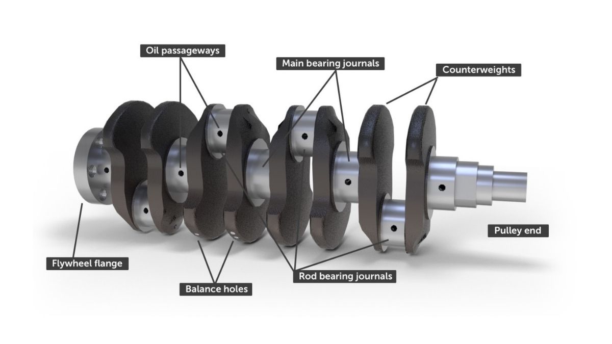
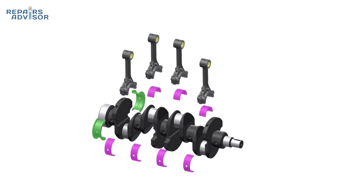
Main bearings support the crankshaft within the engine block, providing the foundation for all engine rotation. These split-shell bearings consist of a steel backing with multiple layers of bearing material designed to handle radial loads from combustion forces and the weight of the rotating assembly.
Steel Backing Shell: The structural foundation provides dimensional stability and heat transfer to the engine block. Typically measuring 0.060-0.080 inches thick, the steel shell maintains precise bearing shape under extreme loads while conducting heat away from the bearing surface to prevent overheating.
Bearing Material Layers: Modern engine bearings use multi-layer construction combining different materials for optimal performance. The overlay layer directly contacts the crankshaft journal, typically made from soft materials like babbitt (lead-tin alloy) or aluminum-tin that provide excellent conformability and embed debris particles.
Barrier Layer: A crucial nickel barrier layer prevents copper migration from the backing material into the overlay, maintaining bearing integrity over extended service life. This layer also provides corrosion resistance and prevents galvanic reactions between different bearing materials.
Connecting Rod Bearing Systems
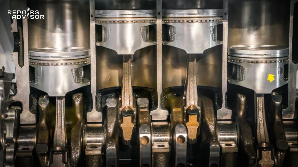
Rod bearings connect the pistons and connecting rods to the crankshaft, handling the explosive forces from combustion while allowing smooth rotation. These bearings experience much higher loads than main bearings due to the reciprocating forces from piston acceleration and deceleration.
Load Distribution Design: Rod bearings feature wider profiles and reinforced backing materials to distribute the tremendous forces generated during combustion. Peak loads can exceed 3,000-5,000 pounds during the power stroke, requiring robust construction and precise clearances for proper oil film formation.
Oil Hole Configuration: Many rod bearings include precisely positioned oil holes that align with crankshaft oil passages to ensure continuous lubrication during high-RPM operation. These holes must be properly positioned during assembly to maintain oil flow to the connecting rod small end and piston pin.
Thrust Bearing Control Systems
Thrust bearings control crankshaft end play, preventing axial movement that could damage seals or affect timing system operation. These specialized bearings handle side loads from manual transmission clutch engagement, automatic transmission converter operation, and internal engine forces.
Flanged Design: Thrust bearing surfaces feature flanged construction with hardened thrust faces that resist wear from constant axial loading. The thrust surfaces are typically integrated into one or more main bearings or provided as separate thrust washers depending on engine design.
Clearance Specifications: Thrust bearing clearances are critical, typically ranging from 0.004″ to 0.012″ depending on engine design. Excessive clearance allows harmful crankshaft movement, while insufficient clearance prevents thermal expansion and can cause bearing failure.
Advanced Bearing Technologies
Tri-Metal Construction: High-performance applications use tri-metal bearings with steel backing, intermediate layer (usually copper-lead), and overlay surface for maximum durability under extreme conditions. This construction provides superior strength, conformability, and fatigue resistance.
Polymer Coatings: Some modern bearings feature polymer coatings that reduce friction during startup and provide protection during boundary lubrication conditions. These coatings are particularly beneficial in engines with start-stop systems or extended oil change intervals.
How Engine Bearings Work: Step-by-Step Operation
Hydrodynamic Lubrication Process
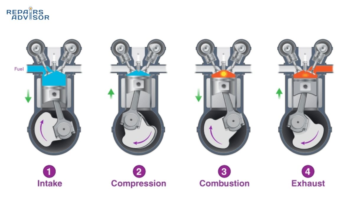
Step 1: Oil Film Formation When the engine starts, the oil pump immediately pressurizes oil through the bearing clearance spaces. As crankshaft rotation increases, the wedge-shaped oil film creates hydrodynamic pressure that literally lifts the crankshaft away from direct bearing contact, creating a protective fluid barrier typically 0.0005-0.002 inches thick.
Step 2: Load Distribution During operation, combustion forces transfer through the connecting rods to the crankshaft journals, where properly functioning bearings distribute these massive loads across the entire bearing surface. The oil film maintains separation between the steel crankshaft and bearing material, preventing metal-to-metal contact and associated wear.
Step 3: Heat Dissipation Bearing clearances allow continuous oil circulation that removes friction-generated heat from the bearing surfaces. The oil cooler system and oil pan work together to maintain optimal oil temperature, ensuring proper viscosity for effective lubrication film formation.
Step 4: Contaminant Management Quality oil filtration systems remove abrasive particles before they reach bearing surfaces, while the soft overlay material in bearings can embed small particles that bypass filtration, preventing damage to the harder crankshaft journals.
Multi-Bearing Coordination
In multi-cylinder engines, all main and rod bearings must work in perfect coordination to support the complex loading patterns created by different pistons firing at various crankshaft positions. The firing order and crankshaft design determine load distribution across all bearing surfaces.
Load Balancing: Engineers design bearing systems to handle both steady-state loads from the rotating assembly weight and dynamic loads from combustion forces. Main bearings near the front and rear of the crankshaft typically handle higher loads due to longer lever arms and accessory drive systems.
Oil Supply Priority: The lubrication system prioritizes main bearings, which receive pressurized oil first, then supply rod bearings through crankshaft internal passages. This hierarchy ensures that the crankshaft support system maintains integrity even under low oil pressure conditions.
Bearing Clearance Management
Critical Clearance Ranges: Main bearing clearances typically range from 0.0015″ to 0.003″, while rod bearing clearances usually measure 0.0015″ to 0.0025″. These precise specifications ensure adequate oil flow for lubrication and cooling while maintaining proper oil pressure throughout the system.
Temperature Compensation: Bearing clearances account for thermal expansion of both the crankshaft and engine block during operation. As engines reach operating temperature, metal expansion reduces bearing clearances, requiring careful initial clearance calculations to prevent binding while maintaining adequate lubrication.
Wear Pattern Analysis: Professional technicians analyze bearing wear patterns to diagnose engine problems, as specific wear patterns indicate issues like insufficient lubrication, contamination, overloading, or improper clearances.
Engine Bearings Location and Access Guide
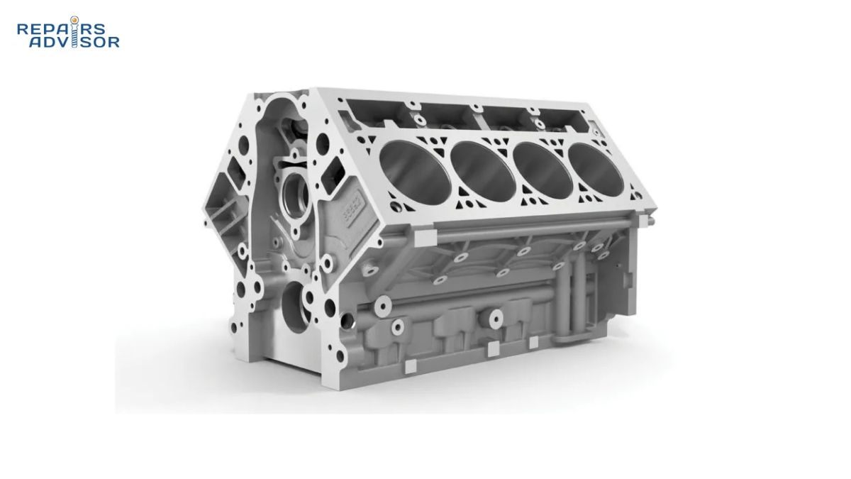
Engine Block Integration Points
Engine bearings integrate into the lowest section of the engine block, with main bearings positioned in the crankcase and rod bearings attached to connecting rods. While bearings themselves are not visible during routine maintenance, several access points allow inspection and service evaluation.
Main Bearing Identification:
- Oil Pan Access: Removing the oil pan exposes the main bearing caps, providing visual inspection of main bearing condition and oil leakage
- Crankshaft Position: Main bearings align with crankshaft main journals, typically numbering 3-7 bearings depending on engine configuration
- Bearing Cap Design: Modern engines use either removable bearing caps or bedplate construction, with bedplates providing superior rigidity
Rod Bearing Assessment:
- Connecting Rod Access: Rod bearings attach to the big end of connecting rods, requiring crankshaft rotation for individual bearing inspection
- Oil Analysis: Regular oil analysis reveals bearing material particles, providing early warning of bearing wear before catastrophic failure
- Visual Inspection: Professional diagnosis includes removing rod bearing caps to examine bearing condition, clearances, and wear patterns
Service Access Requirements
Basic Inspection Level (Professional Only): Oil pan removal allows visual inspection of main bearing areas and oil contamination assessment. However, meaningful bearing evaluation requires precision measuring equipment and complete disassembly procedures beyond DIY capabilities.
Complete Bearing Service (Professional Level): Bearing replacement demands complete engine disassembly, precision measurement of all clearances, proper torque sequences, and clean room assembly procedures. This level of work requires professional facilities, specialized tools, and extensive technical expertise.
Essential Professional Equipment:
- Precision bore gauges and micrometers for clearance measurement
- Plastigauge or dial bore gauges for bearing clearance verification
- Proper torque wrenches calibrated for main and rod bearing specifications
- Clean assembly environment to prevent contamination
- Complete service manual specifications for the specific engine
Vehicle Configuration Considerations
Front-Wheel Drive Applications: Transverse engine mounting may require transmission removal for complete bearing service access. The compact engine bay layout demands specific service procedures and special tools for proper bearing installation.
Rear-Wheel Drive Configuration: Longitudinal engine mounting provides better access to bearing service points, though complete disassembly is still required for bearing replacement. Access to main bearing caps is typically easier in RWD configurations.
Performance Engine Applications: High-performance engines may use upgraded bearing materials, tighter clearances, or specialized bearing designs requiring specific service procedures and measurement techniques beyond standard engines.
Professional Diagnostic Integration
Bearing Failure Symptoms:
- Engine knock or metallic rattling sounds, especially under load
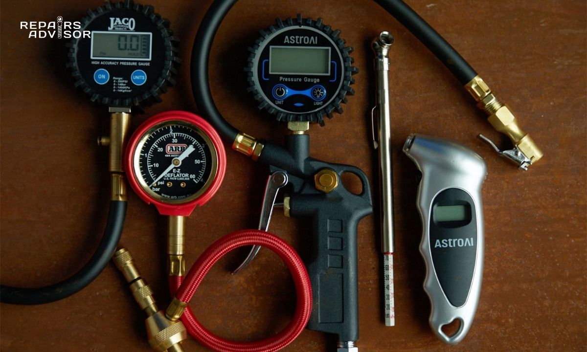
- Low oil pressure readings or fluctuating pressure
- Metal particles visible in oil or discovered during oil changes
- Unusual engine vibration or rough idle conditions
Diagnostic Procedures: Professional diagnosis includes oil pressure testing, bearing clearance measurement, crankshaft journal inspection, and oil analysis to determine bearing condition and replacement requirements.
Service Planning: Bearing replacement typically coincides with complete engine rebuilds due to the extensive disassembly required. Professional shops coordinate bearing service with crankshaft reconditioning, cylinder head work, and related component replacement.
Quality bearing service requires manufacturer-specific procedures, precise clearance specifications, and proper assembly techniques available through professional service manuals. Our comprehensive collection of automotive repair manuals provides detailed bearing service procedures for all major manufacturers including Ford, Toyota, and Honda.
For technical support with manual downloads or bearing service information, contact our customer support team for assistance with technical documentation access.
Information provided for reference only. Engine bearing diagnosis and service requires professional expertise, precision measurement equipment, and complete engine disassembly. Always consult qualified technicians for bearing work and follow manufacturer service procedures for safety and proper engine operation.