The Exhaust Gas Recirculation (EGR) system represents one of the most sophisticated emissions control technologies in modern vehicles, playing a dual role in reducing harmful nitrogen oxide (NOx) emissions while improving fuel efficiency. Understanding how your EGR system functions is essential for maintaining optimal engine performance, meeting environmental regulations, and preventing costly repairs down the road.
For intermediate DIY enthusiasts, grasping EGR system operation opens the door to diagnosing common driveability issues like rough idling, reduced power, and poor fuel economy. Professional mechanics rely on detailed EGR system knowledge to quickly pinpoint failure modes using diagnostic scan tools and live data analysis. Even beginners benefit from understanding this system’s basic function, as EGR-related problems often trigger check engine lights and can be confused with other engine issues.
The EGR system works by recirculating a portion of exhaust gases back into the engine’s combustion chambers, lowering peak combustion temperatures and reducing NOx formation. This seemingly simple concept involves complex coordination between multiple components, sensors, and the engine control unit (ECU). When functioning properly, the EGR system reduces emissions by up to 50% while maintaining smooth engine operation across all driving conditions.
Modern vehicles employ either vacuum-operated or electronically-controlled EGR valves, with many newer models using sophisticated EGR coolers to further reduce combustion temperatures. Diesel engines often feature more aggressive EGR strategies, recirculating up to 40% of exhaust gases under certain conditions. Understanding your specific vehicle’s EGR configuration is crucial for effective troubleshooting and maintenance.
Safety Note: Working with EGR systems involves hot exhaust components and potential exposure to carbon deposits. Always allow the engine to cool completely before inspection or service work. Professionals should use appropriate personal protective equipment when handling EGR components.
EGR System Parts and Construction Explained
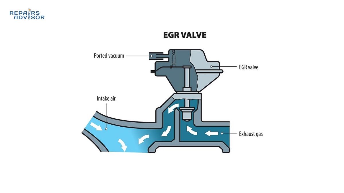
The EGR system consists of several interconnected components that work together to precisely control exhaust gas recirculation. At the heart of the system sits the EGR valve, which opens and closes to regulate exhaust flow back into the intake manifold. Traditional vacuum-operated valves use engine vacuum and a vacuum solenoid controlled by the ECU, while modern electronic valves employ stepper motors or linear actuators for precise control.
The EGR cooler (found on most vehicles built after 2005) uses engine coolant to lower exhaust gas temperatures before they enter the intake system. This cooling process allows for higher recirculation rates without risking engine damage from excessive heat. The cooler typically features a tube-and-fin design similar to a small radiator, with exhaust gases flowing through one side and coolant through the other. When EGR coolers fail, they can leak coolant into the exhaust system or allow exhaust gases to contaminate the cooling system.
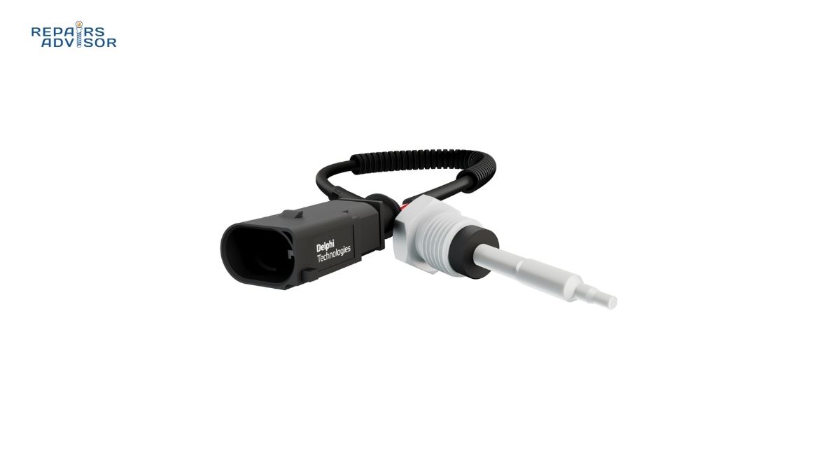
EGR position sensors provide critical feedback to the ECU about valve position and flow rate. These sensors may be integrated into the valve assembly or mounted separately, using either potentiometer-style sensors or newer Hall-effect technology. The engine control unit continuously monitors these signals to ensure the valve opens and closes precisely as commanded.
The EGR passages route exhaust gases from the exhaust manifold through the EGR valve and into the intake manifold. These passages are particularly prone to carbon buildup, which can restrict flow and cause system malfunctions. Many engines feature EGR passages cast directly into the cylinder head or intake manifold, making cleaning procedures more complex. Some vehicles use external EGR pipes that can be removed for service.
Differential Pressure Feedback (DPFE) sensors or EGR temperature sensors provide additional monitoring capabilities on many vehicles. The DPFE sensor measures the pressure difference across an orifice in the EGR system to calculate actual flow rates, while temperature sensors verify that exhaust gases are flowing when the valve opens. These redundant monitoring systems help the ECU detect EGR system failures quickly.
For diesel applications, additional components may include EGR throttle valves in the intake system to create the vacuum necessary for EGR flow, and EGR mixing chambers to ensure even distribution of recirculated gases across all cylinders. Understanding these diesel-specific components is essential when working on modern turbocharger-equipped engines.
Professional Insight: Many technicians overlook the importance of the EGR vacuum solenoid or electronic control valve. These components can fail intermittently, causing frustrating driveability issues that don’t always set diagnostic trouble codes. Testing these components with a scan tool’s bi-directional controls often reveals problems that voltage testing alone might miss.
How EGR Systems Work: Step-by-Step Operation
Understanding EGR system operation requires following the complete control loop from ECU command through valve actuation to exhaust gas recirculation. The process begins with the ECU analyzing multiple input signals including engine speed, load, throttle position, coolant temperature, and intake air temperature. Using programmed maps and algorithms, the ECU determines the optimal EGR flow rate for current operating conditions.
During cold engine operation, the ECU typically commands the EGR valve fully closed. Recirculating exhaust gases when the engine is cold would worsen emissions, reduce driveability, and slow engine warm-up. Most systems don’t activate EGR flow until coolant temperature exceeds 130-140°F (54-60°C). This cold-start strategy is why some EGR system problems only manifest after the engine reaches normal operating temperature.
Once warm-up completes, the ECU begins modulating EGR valve position based on driving conditions. At steady cruising speeds with light throttle, the valve may open 30-50%, significantly reducing combustion temperatures and NOx formation. The fuel injection system compensates for the reduced oxygen content in the intake charge by adjusting fuel delivery to maintain the proper air-fuel ratio.
During acceleration or high-load conditions, the ECU commands the EGR valve closed to maximize available oxygen for combustion. This ensures optimal power delivery when drivers need it most. The rapid opening and closing of the EGR valve during transitional driving conditions demonstrates the sophisticated control strategies modern engines employ. Professional technicians can observe these real-time adjustments using a scan tool’s graphing function.
The feedback loop constantly verifies EGR system operation. The ECU monitors EGR valve position sensors to confirm the valve moves as commanded. On systems with DPFE sensors, the ECU compares actual flow rates against expected values. If the system detects discrepancies between commanded and actual EGR flow, it may set diagnostic trouble codes like P0401 (EGR Flow Insufficient) or P0402 (EGR Flow Excessive).
Deceleration fuel cutoff (DFCO) events present interesting EGR control challenges. When drivers release the throttle at speed, many engines stop injecting fuel to save gas. During these events, the ECU must manage EGR valve position carefully to ensure smooth engine operation when fuel injection resumes. Poor EGR control during DFCO transitions can cause stumbling or hesitation.
For diesel engines, EGR operation becomes even more complex due to the lack of throttle plates creating intake vacuum. These systems typically use variable geometry turbochargers or intake throttle valves to create the pressure differential needed to drive exhaust gases into the intake. The coordination between the turbo, EGR valve, and intake throttle requires precise calibration to prevent turbo surge and maintain smooth operation.
Beginner Tip: If your check engine light illuminates and you notice rough idling or poor acceleration, the EGR system is a likely culprit. Before assuming expensive repairs, consider that many EGR problems stem from simple carbon buildup that can be cleaned. Professional diagnosis with a scan tool will quickly identify whether your symptoms point to EGR system issues.
EGR System Location and Access Guide
Locating EGR system components requires understanding typical engine bay layouts and how exhaust routing affects component placement. The EGR valve typically mounts on or near the intake manifold, positioned to receive exhaust gases from the exhaust manifold or turbocharger outlet. On transverse-mounted engines common in front-wheel-drive vehicles, look toward the rear of the engine bay where the exhaust manifold meets the cylinder head.
Longitudinally-mounted engines (rear-wheel-drive and all-wheel-drive vehicles) often position the EGR valve on the intake manifold’s passenger side, though this varies by manufacturer. V-configuration engines may have EGR valves on both cylinder banks or a single centrally-mounted valve. The intake manifold design significantly influences EGR valve accessibility, with some installations requiring removal of air intake components or engine covers for access.
EGR coolers mount between the exhaust source and EGR valve, often tucked deep in the engine bay where coolant lines can reach them easily. On many vehicles, the cooler sits beneath the intake manifold, making inspection difficult without removing upper engine components. Some manufacturers integrate the EGR cooler into the exhaust manifold casting, creating a particularly challenging service situation when replacement becomes necessary.
The EGR passages route through the cylinder head or intake manifold, making them completely inaccessible without significant disassembly. External EGR pipes (common on older vehicles and some diesels) follow the outside of the engine block, making them easier to inspect and clean. These external pipes often show visible signs of problems like cracks, loose connections, or excessive carbon buildup at joints.
Vacuum solenoids and electronic control valves typically mount on the engine valley cover, firewall, or intake manifold in locations protected from excessive heat. Following vacuum lines or wiring harnesses from the EGR valve usually leads to these components. Professional technicians appreciate well-organized engine bays where EGR control components mount in logical, accessible locations.
For diesel engines, locating all EGR system components can be particularly challenging due to the complexity of modern emissions systems. The EGR cooler may integrate with the oil cooler or charge air cooler, creating a multi-function heat exchanger assembly. Understanding your specific diesel engine’s layout is crucial before attempting any EGR system service work.
Access procedures for EGR system service vary dramatically by vehicle. Simple jobs like replacing an EGR valve might require only removing an air intake tube and disconnecting a vacuum line and electrical connector. Complex situations may demand removing the intake manifold, alternator, power steering pump, or even the turbocharger to reach deeply-buried components. Always consult vehicle-specific repair procedures before beginning work.
Professional Strategy: Before quoting EGR system repairs, experienced technicians perform thorough access assessments using service information and their knowledge of similar vehicles. Some seemingly simple component replacements turn into extensive jobs due to poor accessibility. Setting proper customer expectations about labor time prevents disputes and ensures profitable repairs.
Safety Reminder: EGR system components remain hot long after engine shutdown. Always verify surfaces have cooled to safe temperatures before attempting to remove components. Coolant system depressurization is essential before disconnecting EGR cooler lines, as residual pressure can spray hot coolant. Professional mechanics follow proper lockout procedures and wear appropriate personal protective equipment when working on emissions systems.
Related Maintenance and Troubleshooting Resources
Understanding your EGR system connects to broader vehicle maintenance and diagnostic knowledge. Explore these related topics to build comprehensive automotive expertise:
Emissions Control Systems
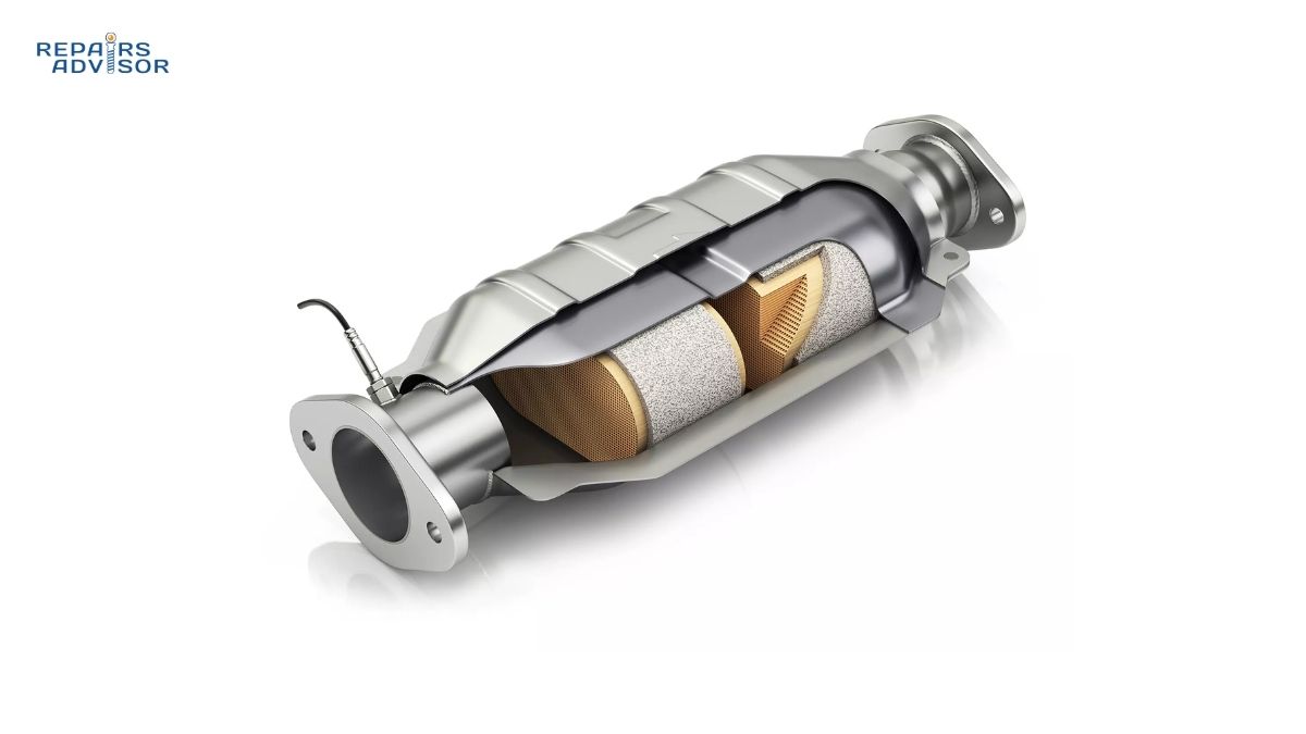
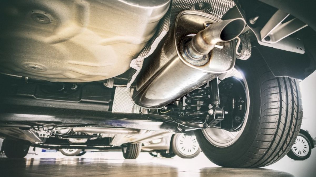
- Catalytic Converter Function and Maintenance – How EGR systems work with catalytic converters to reduce emissions
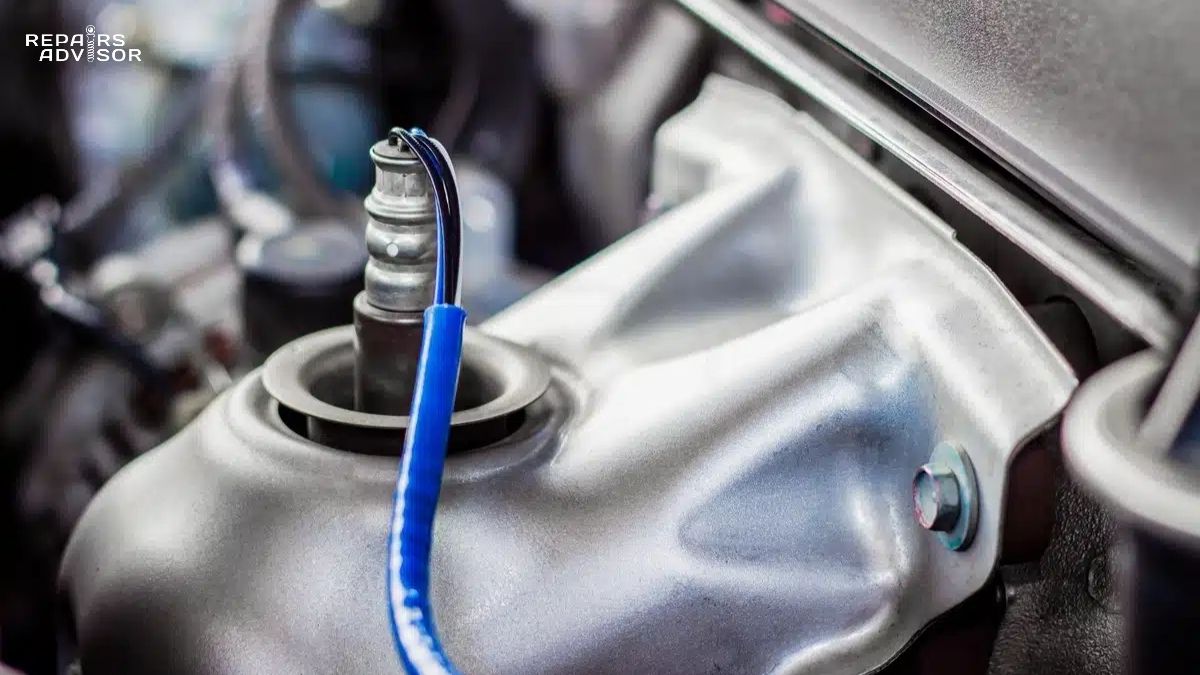
- Oxygen Sensors and Air-Fuel Ratio – Understanding how O2 sensors monitor EGR system effectiveness
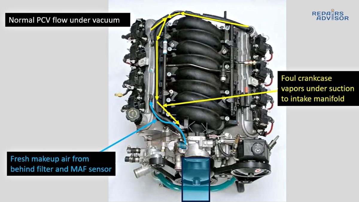
- PCV System Operation – The relationship between crankcase ventilation and EGR function
Engine Performance Components
- Intake Manifold Design and Function – Where recirculated exhaust gases mix with fresh air
- Throttle Body and Airflow Control – How throttle position affects EGR valve operation
- Mass Airflow Sensor Operation – Measuring total airflow including recirculated gases
Diagnostic Procedures
- OBD-II Diagnostic Trouble Codes – Understanding P0400-series EGR system codes
- Scan Tool Data Analysis – Monitoring real-time EGR valve position and flow rates
- Engine Performance Troubleshooting – Systematic approach to identifying EGR-related driveability problems
For vehicle-specific EGR system information, service procedures, and wiring diagrams, explore our comprehensive collection of repair manuals organized by manufacturer. Need help accessing technical documentation? Visit our Help Center for guidance on downloading and using repair manual files.
Final Note: EGR system maintenance prevents costly repairs and maintains optimal fuel efficiency. Regular inspection and cleaning every 50,000-75,000 miles helps avoid common problems like valve sticking and passage restriction. When problems arise, systematic diagnosis using proper scan tool data and service information leads to efficient, accurate repairs.